When you click on links to various merchants on this site and make a purchase, this can result in this site earning a commission. Affiliate programs and affiliations include, but are not limited to, the eBay Partner Network.
Apologies if you are certain, but are you 100% sure that you have the RCAs marked AUDIO OUT on the HU connected to RCAs marked IN on the MOST box? I would double-check this because you should definitely be seeing a signal on the RCAs that you connected to the small speakers, and it seems you are not.
I am certain. I connected the computer speakers to all of the RCA ports on the HU just to make sure I wasn’t missing anything. I tried playing something from radio and CarPlay but no joy. I can double check my volume again but I am also positive that I turned my volume way up before disconnecting the original unit. I turned it up and remember thinking to myself damn the echo in my garage is bad.
I am certain. I connected the computer speakers to all of the RCA ports on the HU just to make sure I wasn�t missing anything. I tried playing something from radio and CarPlay but no joy. I can double check my volume again but I am also positive that I turned my volume way up before disconnecting the original unit. I turned it up and remember thinking to myself damn the echo in my garage is bad.
Edit: Volume was good on the original head unit
Something suggests there may be a fault in one of your components then. If the HU is working properly, connecting the audio outputs to the MOST inputs is guaranteed to produce sound. This assumes that the MOST box is correctly powered, which you assure us it is, and that the fibre optic (orange) cable is properly inserted. You have, in any case, ruled out a fault with the MOST box by connecting small outboard speakers directly to the analog (RCA) outputs from the HU. Have you tried using your DMM to look for output on the RCA outputs from the HU. If you can confirm an output there, that will mean that the HU is delivering a signal. This then takes us back to the MOST box and its connections, or possibly to the external (OEM) amplifier. I have installed 4 of these, or similar, units and have read about the installation of dozens more and I have not yet encountered a case with BOSE where the OEM amplifier needs a 'trigger' signal. I think that is the one remaining thing you have yet to try, so good luck and please let us know how you got on.
Yay! I finally figured out what went wrong. I was testing the RCA outputs like you said and I was thinking about what you said about eliminating the MOST adapter as the faulty component. So then I realized that I had only checked for power on the MOST adapter, but that only accounts for the red and the black wire. I took the connector off to the MOST adapter and pulled the harness to the car and tested for continuity on the yellow wire and sure enough, I didn't get a beep. After recrimping the yellow wire, I finally got audio. Thank you so much for your help. Looking back at it, this install was super simple.
That said, on all of your installs, did you run into the issue of the HU not turning off on its own? I had to repin the red wire on the HU harness side because the red wire was connected to a constant 12v on the car side. I used my DMM to find a 12v wire that loses power after I take the keys out of the ignition and repinned the red wire to that.
Basically I did what this guy did at 18 minutes in:
Yay! I finally figured out what went wrong. I was testing the RCA outputs like you said and I was thinking about what you said about eliminating the MOST adapter as the faulty component. So then I realized that I had only checked for power on the MOST adapter, but that only accounts for the red and the black wire. I took the connector off to the MOST adapter and pulled the harness to the car and tested for continuity on the yellow wire and sure enough, I didn't get a beep. After recrimping the yellow wire, I finally got audio. Thank you so much for your help. Looking back at it, this install was super simple.
Way to go, buddy! Glad you got it sorted.
Originally Posted by A911Fan
That said, on all of your installs, did you run into the issue of the HU not turning off on its own? I had to repin the red wire on the HU harness side because the red wire was connected to a constant 12v on the car side. I used my DMM to find a 12v wire that loses power after I take the keys out of the ignition and repinned the red wire to that.
Usually, if the HU isn't turning off it means that the installer has connected the Battery 12v+ constant (yellow) wire where he should have connected the 12V+ ACC (red) switched wire. There are so many wires it's an easy mistake to make. Your method is good - so long as you hook into a switched feed, you are going to be OK. Some devices have both a red feed and a yellow feed - this is for when a device needs a constant 12V supply - for example, to retain the station presets in your radio, but also needs to turn off the main device when the car is off.
Having a DMM and knowing how to use it is a really useful tool for these kind of situations, as you discovered!
Re Michael's post #691 from 12 months ago (below), I'm installing back up cam into my 997.1 manual.
Does anyone have a schematic they could share that details Michael's comments below (highlighted in red) because no matter how many times I've read this it remains ambiguous.
TIA
Originally Posted by myw
in case i missed this - this should explain everything clearly.
the pink wire (there are 2 of them) are reverse trigger inputs. the primary reverse trigger is on the main 20-pin main harness (technically comes out of the canBus unit) along with main rear cam RCA input , the 2ndary reverse trigger is on the 6-pin video harness only (which has the front cam RCA input as well as CamPWR + CamGND, and ANOTHER rear cam RCA input). Both pink wires (primary + 2ndary) are routed to the same circuit inside the unit. Both rear cam RCA inputs (primary + 2ndary) are also routed to the same rear RCA video input circuit inside the unit.
NEITHER pink reverse trigger wires provides power to the camera. All it does is wait to receive a 12v signal (to be spliced to the reverseLight wire) from the black/blue taillight / kickPanel (yes they are the same wire). Upon receiving the 12v, you will hear a 'click' and the unit will flip into reverseCamera RCA input mode. As it does this, camPWR (from the 6-pin video harness) will now fire up and sends out 200ma, which is used to power the camera (both front and rear cameras is to be spliced here and hence BOTH cameras turn on at the same time). This way the cameras are ONLY when needed (ie. in REVERSE or when the fCam app is on), extending the life of the cameras (they are not to ever recieve a constant 12V). Once the car is no longer in reverse, the pink reverse trigger stops receiving a signal... the unit will flip out of reverse cam RCA input mode (the cams will still be powered for up to 10 more seconds ).
The reason why 2 pink wires can be 'tied' together via the metal adapter is because the primary reverse trigger for the autoTranCars can come from the canBus module (a pink wire comes out of the canbus module, which gets tied to the pinkWire going into the primary 20 pin harness). In this case the black/blue wire connections arent needed.
To get the unit + cameras working as intended, BOTH rear + front cameraPWR + camGND are to be spliced to the 6-pin videoCam-specific harness. This ensures clean power + gnd to the camera reducing any chances of flicker caused from bad splices or shared GND. The trick to make this happen is to also fish a DC extension cable when fishing the videoCam (yellow RCA + red 22 guage) cable.... one end of the DC extension cable plugs into the cam, while the other end plugs into the cameras supplied black + red wired connectors ... which will splice into the PCM itself.
Now the 22 guage red cable (the one attached to the yellow RCA video cable) is ONLY to be used in the case where we have a manual transmission car needing to transfer the reverseLight signal (from the tail light) and on the pcm end, will be spliced into either the primary or 2ndary pink reverse trigger cables (either will work).
This ensures the reverse camera will work the same way oem car systems work - they are powered by the PCM ONLY, but power to the cameras occur when the PCM receives a reverse input trigger signal.
Now that only the PCM powers the cameras - the beauty is that the Fcam app - being a built in (hardware) android app actually fires up the camPWR (in the 6 pin video harness) and turns on both cameras whenever the fCam app is on. Also being an android (hardware) app, the fCam app is one of the few apps that can actually be mapped to the pcm buttons, or steering wheel button. The default display is the front cam when using the fCAM app - you can see how useful this will be by just clicking a button on the steering wheel when approaching a ramp/curb and the front parking camera output shows on the screen.
While your at it, you can check out the rear camera as well while in any gear. Also when wired correctly this way, you can set it in the secret menu for the front camera Delay. It is a feature that after the car comes out of reverse, the front camera will come on (for up to 10 seconds, you can set to less or turn off this feature completely) before switching back automatically to whatever previous app you were running. This is very useful for multi-point turns in tight spots as you will automatically see both front + rear cams as you switch gears, without having to do anything. And after 10 seconds, the power to both front + rear cameras automatically turns off reducing battery drain and increasing the life of the cameras (as should be).
With the new generation of AHD cameras and reverse cams also being front cameras too, make sure that you cut/don't cut the wires that pertain to
- AHD
- image mirroring
- parking lines
to the correct settings, depending on the application and preference. I dont bother with the ugly parking lines out of the camera - as they can be set via various lengths in the PCM (not to mention for the auto 911 owners, the steering angle sensor info will actually get the reverse lines to move via the canBus i believe. But remember to cut (or not cut) the line that sets image mirroring, depending on if you use the camera for front, or reverse (mirrored image) cam.
Re Michael's post #691 from 12 months ago (below), I'm installing back up cam into my 997.1 manual.
Does anyone have a schematic they could share that details Michael's comments below (highlighted in red) because no matter how many times I've read this it remains ambiguous.
TIA
are you installing a camera for a PCCM HU or another Android-based unit?
Michael is saying that one should run a separate (power+ground) wire from the camera to the PCCM, and to only use the piggyback red wire attached to the camera video signal (yellow RCA plugs) if the PCCM needs an external trigger to know when the car is in reverse (which would come from the tail lights).
In the (2) 997.1 installs I've done with aftermarket rear cameras, on the camera end I simply connect the red piggyback wire to the camera +12v, leaving the ground wire disconnected. At the HU end, the red piggyback wire connects to the HU CAM +12v output, and the reverse trigger (pink) on the main harness is wired to the tail light output from under the driver seat.
Thanks Matt for your quick reply which makes sense. Should have mentioned I'm installing an Aliexpress Android Unit. I've since scoured YT videos and found one which explains Michael's suggestion.
I'm planning to run a single 18 gauge wire with the video RCA/piggy back convenience wire. At the HU 18 gauge will connect to the HU CAM +12v output, RCA to rear cam IN and the piggy back to reverse trigger (pink).
Down the back, 18 gauge will connect to cam power, RCA to CAM RCA and convenience wire to tail light reverse wire (Blue/Black) in tail light harness. I'll ground the CAM to tail light harness as well (brown is ground).
that's overkill IMO, but you do you.
here's what mine look like:
main wiring harness, reverse trigger wire (brown) extended with quick disconnect (blue wire) runs to module under driver seat connection under driver seat camera wiring to HU
this is for the unit with the higher end componets 20 - pin main harness (more expensive unit)... with the functional SD card slot etc.
the more popular unit that most ppl have purchased... while it also uses the faceplate i designed it is a different unit all together and uses different components, including a different main wiring harness (16 pin?). I suspect there are other differences as well (color of wires etc).
Nevertheless the theory behind it all should be the same.
Originally Posted by Einsteiny
Re Michael's post #691 from 12 months ago (below), I'm installing back up cam into my 997.1 manual.
Does anyone have a schematic they could share that details Michael's comments below (highlighted in red) because no matter how many times I've read this it remains ambiguous.
TIA
Thanks for chipping in Michael, good to hear from you! Based on our PMs I bought the QCM Owtosin with 20 pin harness and functional SD card (they are on great special at the moment). Using your instructions I've bench tested the rear camera prior to install and is working as it should.
I ordered a front camera as well and noticed it didn't come with the shorter +12v red and black cable going to a black plug which plugs in the camera end to give power. I only have the yellow RCA with attached red convenience wire provided with the camera. Is that usual or will I need the other shorter cable as well to power the front camera? If so, do you know what it's called so I can get in touch with Bob?
**EDIT
Disregard. I need to get power to the CAM so I ordered the required cable online - 5 pack from Temu for AU$2.86.
Originally Posted by myw
this is for the unit with the higher end componets 20 - pin main harness. this is the more expensive unit. with the functional SD card slot etc.
the more popular unit that most ppl have purchased... while it also uses the faceplate i designed it is a different unit all together and uses different components, including a different main wiring harness (16 pin?). I suspect there are other differences as well (color of wires etc).
Nevertheless the theory behind it all should be the same.
It seems that my second Heregoes unit is also lost in transit after they agreed to sent a replacement because the first one's tracking hadn't moved in weeks. Was looking forward to this weekend to install it but doesn't look like it'll arrive on time, if it arrives at all. For context, I placed the order on January 25th.
Well, my HU turned up today, so after a couple of months of reading your installs, I am ready to ask about mine sorry in advance about the lengthy post but I want to do it right the first time.
First things first, this is my setup:
- 997.1 manual car with BOSE, European.
- not planning on installing rear camera for the time being
- Heregoes unit (this one: https://es.aliexpress.com/item/1005005086544248.html) - 7862 processor, MOST box, 8G RAM
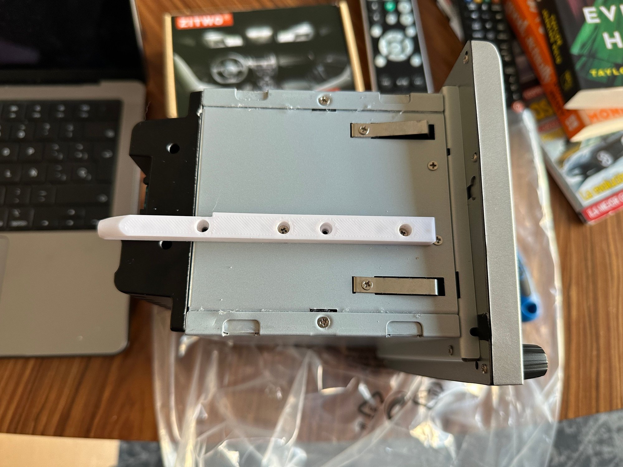
First thing I did, replace the rails with 3D printed ones so the unit doesn't move:
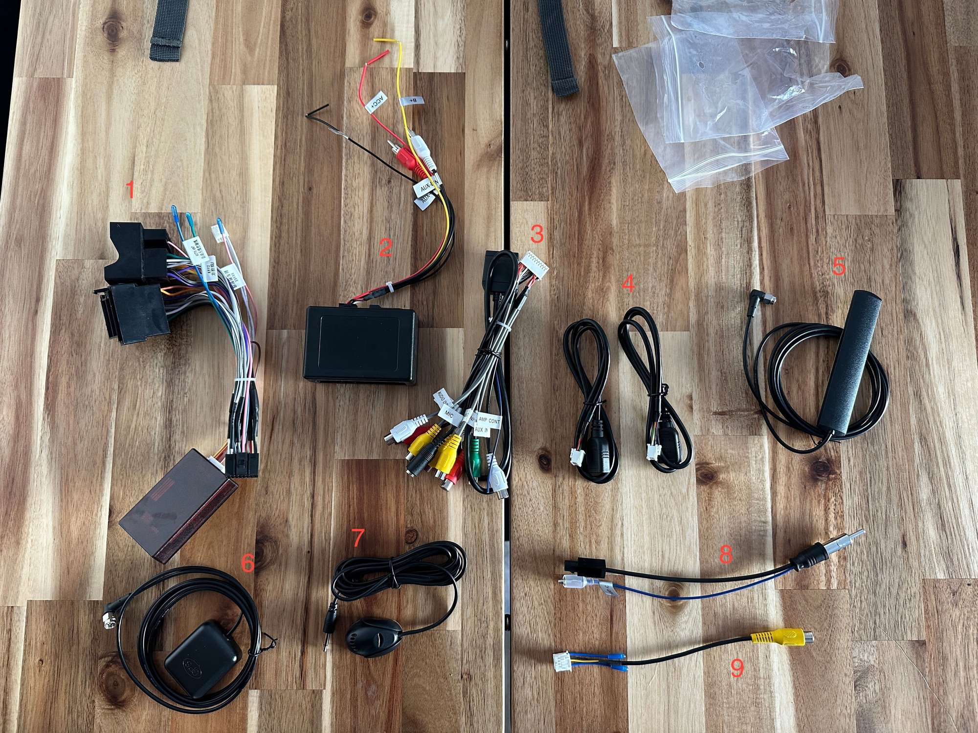
These are the cables that I got:
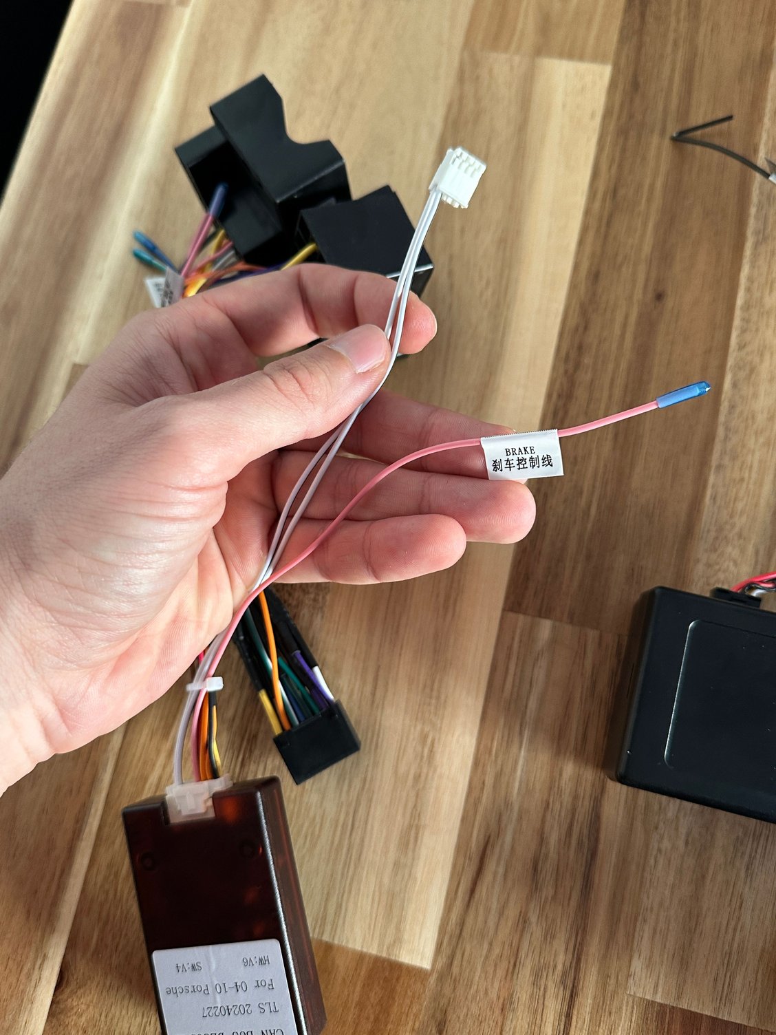
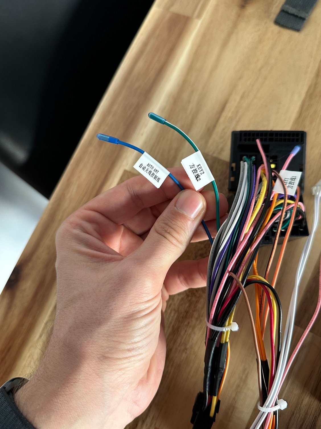
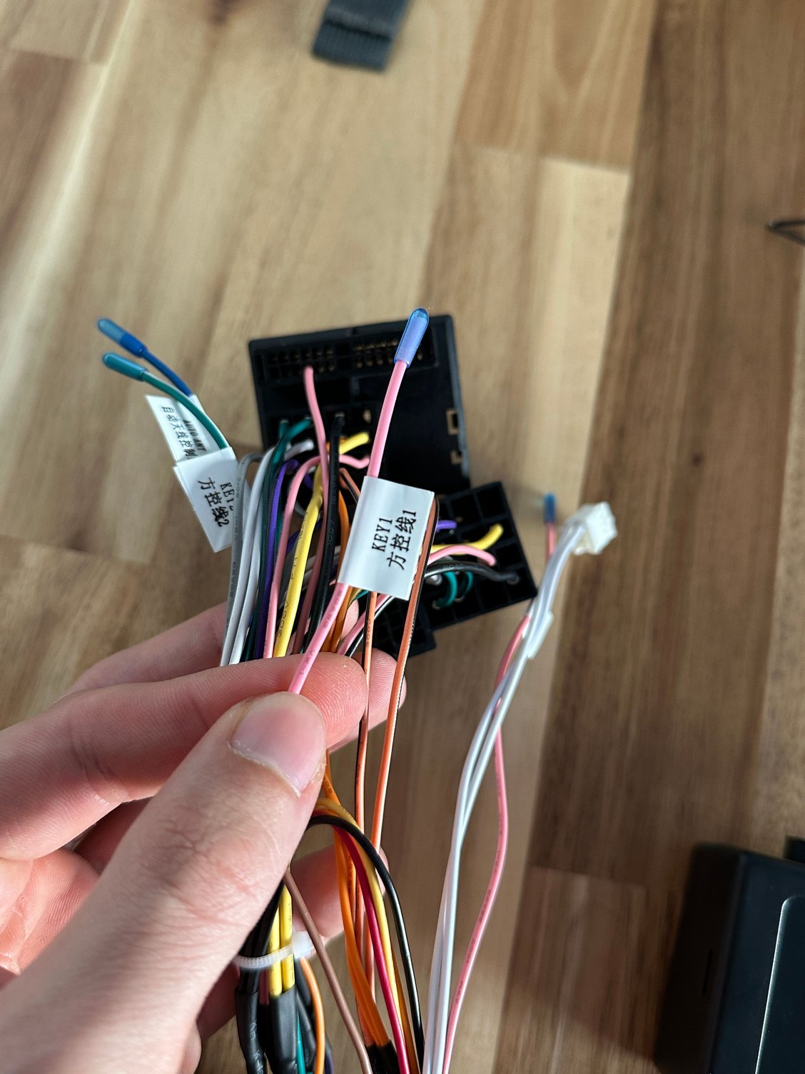
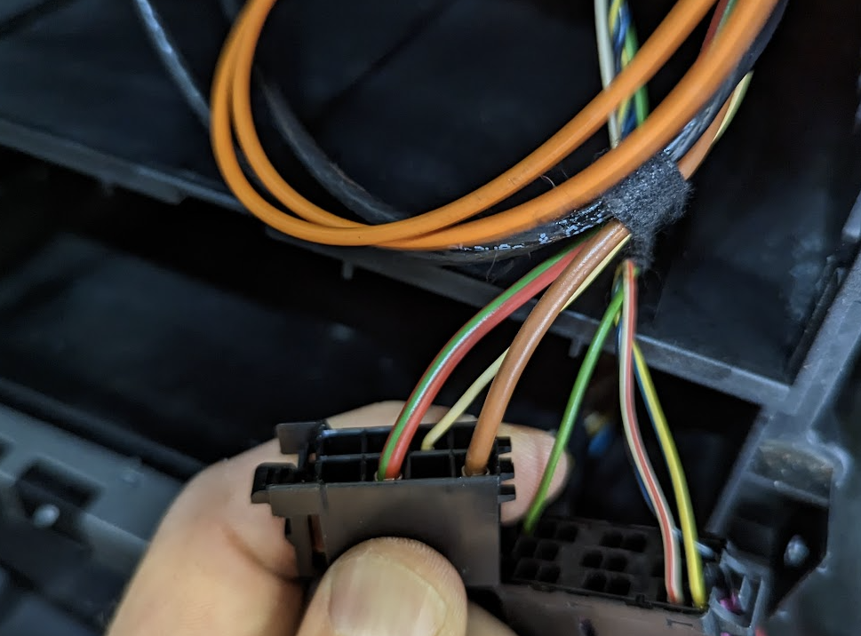
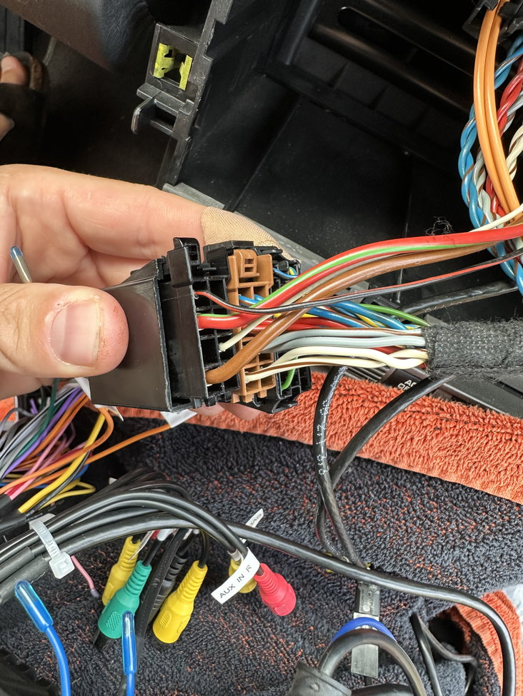
And some close ups of the main harness:
My plan:
1 - Cut the connector off the main harness (1 in the photo above) that does not go with my car (I still need to check which one it is), cover the cut cables with heat shrink.
2 - From the cut cables of the connector I won't be using, get ground, constant power and key on power and solder those to the MOST box (2 in the picture). For Heregoes units (and I'll ping @MattDevoCustoms here because I think these are the ones he recommends), is it safe to assume that I can just connect to cables of the same color (red, yellow, black) on the main harness?
3 - I've also seen a mention of having to power up the BOSE amp. I will check which cable it is in the car connector and then add the pink wire labeled "Auto amp" in the harness to the correct place in the connector (the cables come already pinned, so it's only a matter of putting it where it belongs)
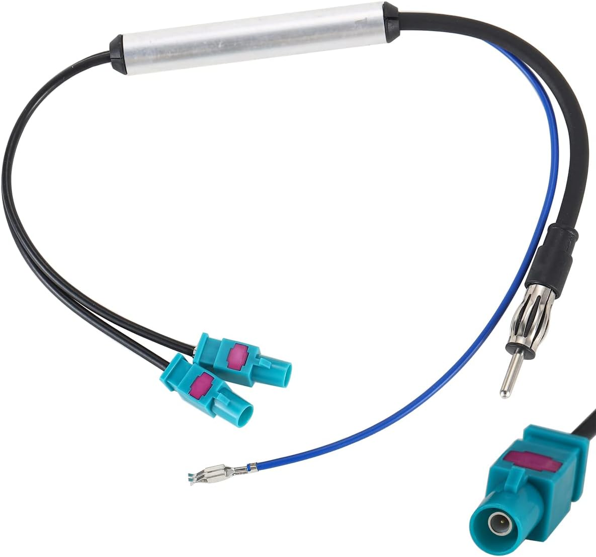
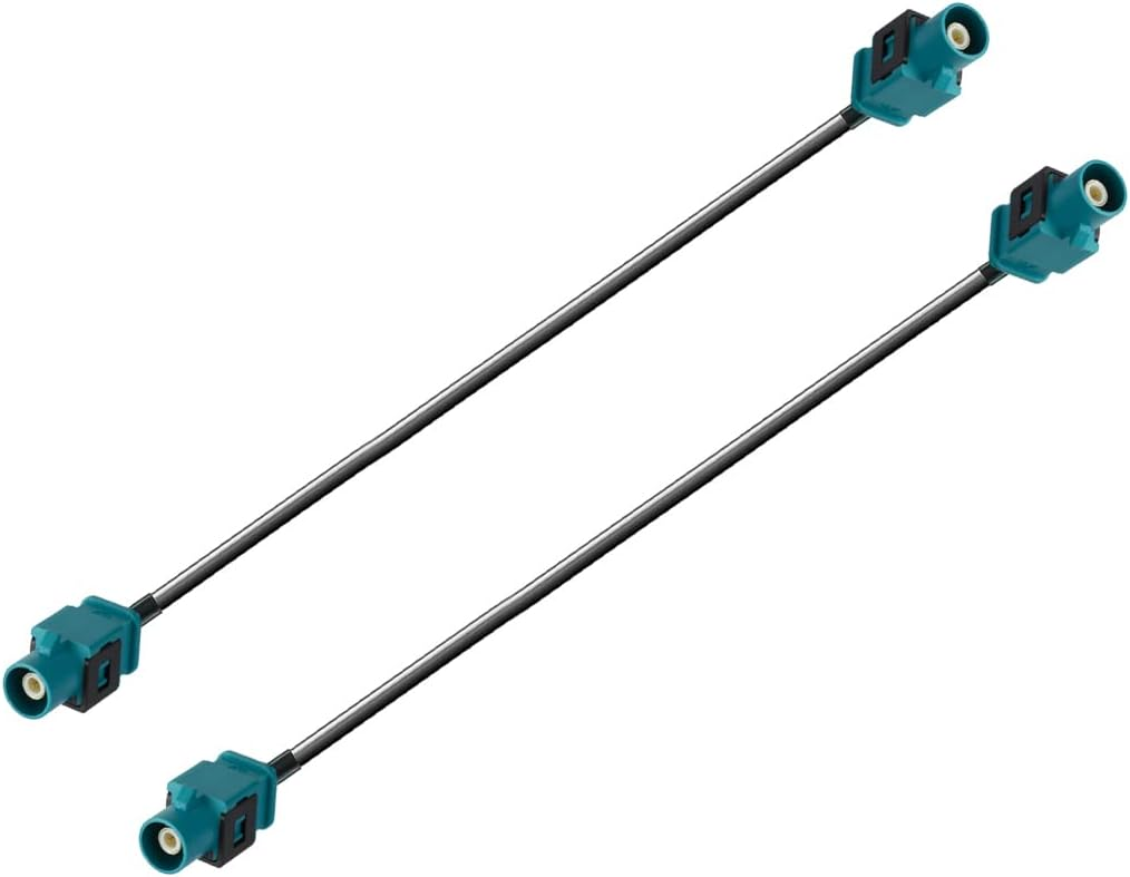
4 - I will replace the antenna and ditch that cable (number 8 in my picture) for a dual fakra one, like this:
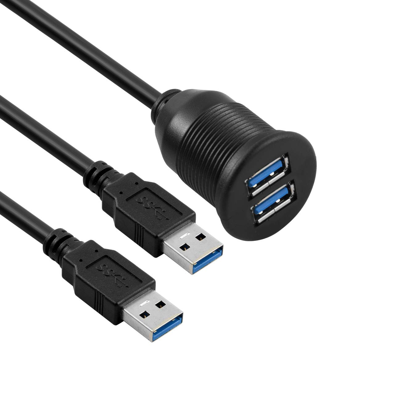
5 - I will cut the connectors for the USB cables (4 in my picture) and solder them to this, so I can replace the cigarette lighter in the passenger footwell. Or I may just connect everything even if I have long cables laying around, we'll see:
6 - Since I won't be using a rear camera, I will just connect cable number 9 as it is
7 - Since I won't be adding a SIM card (cable number 3), I'll leave the socket empty and won't use cable number 5
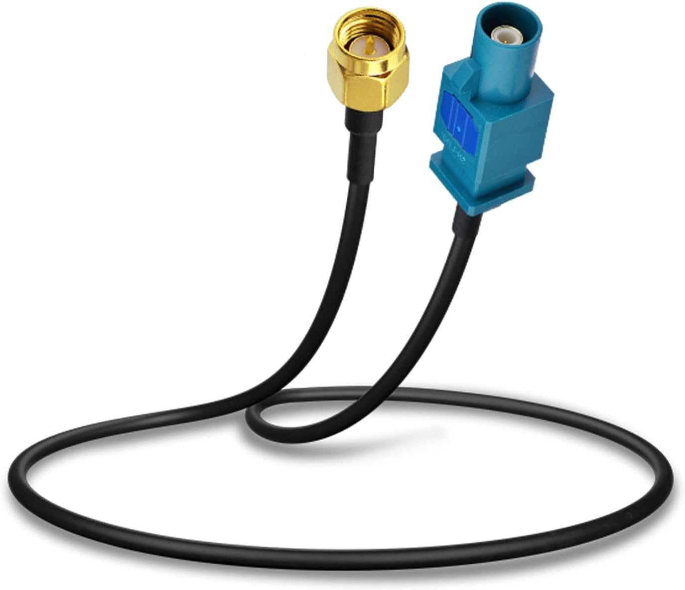
8 - I will replace the GPS antenna with the one that the car already has. For this, I will replace cable number 6 for this one:
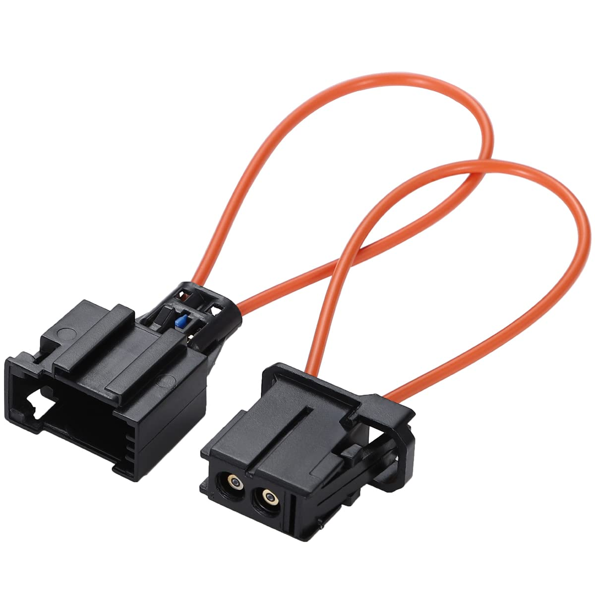
9 - I will use two of these cables to bypass the Porsche antenna adapter (passenger side console, under edge of carpet) (couldn't find a dual one):
Now, question time:
1 - I remember reading that I should get one of these if I wanted to remove the nav, or something else that was in the frunk (can't remember what it was now) in order to not "break" the MOST circuit. What was it that could be removed, where is it and is the connector I need to buy male or female?
2 - Regarding point number 3 in my plan, which cable is the one that I need to power, the yellow thin one or the black/red thin one? I've seen it mentioned in the posts that had these images attached, but one of the pictures is missing the red/black cable. That's where my Auto Ant (blue cable in the harness I got) goes?
3 - The cables in my harness labeled "Brake", "Key1", "Key2". What are they?
4 - The connector that comes out of the CANBUS box (white and white/black wire, see picture above), what is it? Does it go to the head unit? I assume it does because there's only one female 8-pin connector.
5 - Can I reuse the OEM microphone? If so, how? The one that comes with the unit is bulky and ugly, but I'll install it if I can't reuse the OEM one because I have an Android HU in another car and the integrated mic sucks.
6 - Where is the OEM GPS antenna located? The connector I have in my Amazon cart is 30cm long (12 inches), will it be long enough or should I get a longer one?
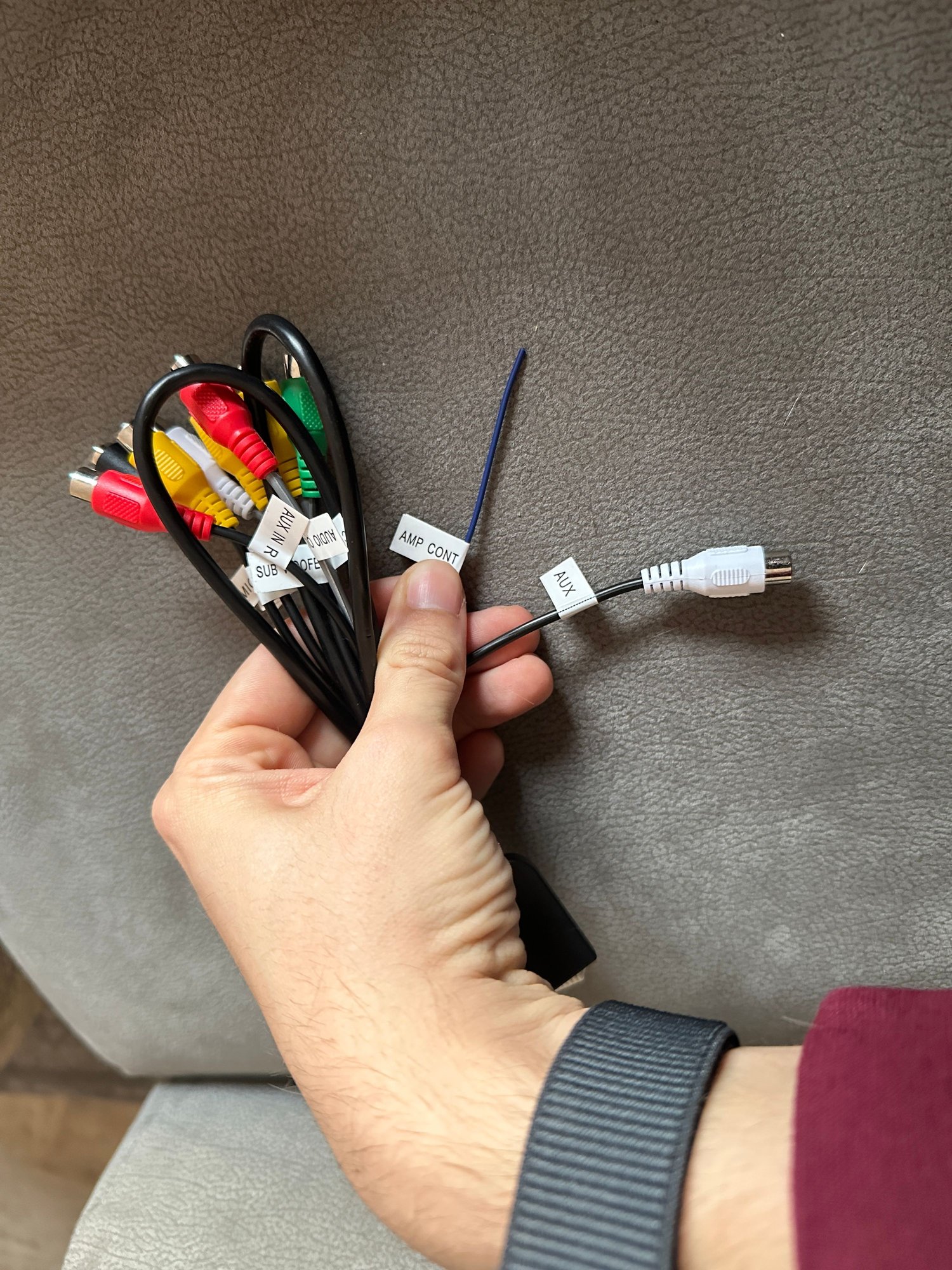
7 - In the harness number 3 in the photo there�s a wire which says AMP CONT. Where does that one go?
7) Yea I think you�re overthinking this. I spent about 20 hours total on my install. Looking back at it now, the only thing I had to do was connect all the cables that it came with to the back of the unit. Then cut the harness that wasn�t meant for my car. Crimp the MOST box onto the three respective wires. Check for continuity on those three wires to make sure the crimp is good. Check for the power wire on the HU�s harness that it is connected to an ignition power and not constant. Slap it back in and call it a day. If I were to do it all over again, I would have had it all done in 2 hours or less. Doesn�t help that Heregoes units don�t really come with instructions or troubleshooting steps.


 03-14-2024, 07:50 PM


 sorry in advance about the lengthy post but I want to do it right the first time.