When you click on links to various merchants on this site and make a purchase, this can result in this site earning a commission. Affiliate programs and affiliations include, but are not limited to, the eBay Partner Network.
Hi FMPorsche - based on the C4 version and the config code, i believe you have purchased the public/wholesale units... this is not my unit via any of the links I've ever shared.
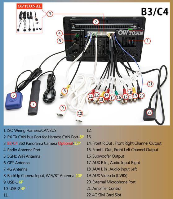
It is from owTowsins low end line (completely different internals including the casing + heatSink).
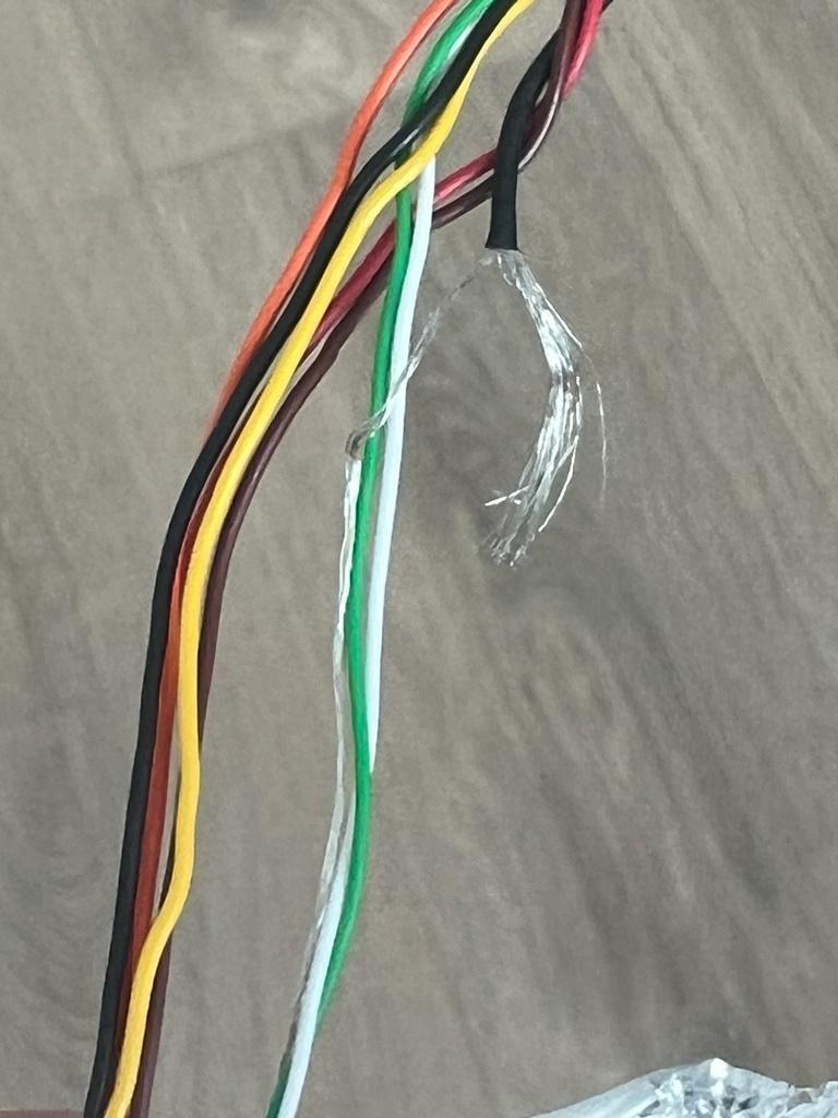
I can tell from your image that as far as the, harnesses, pinOuts for the wires, some of the cable ends to be spliced, are all completely different from the higher end line. Are those 2 short wires coming out of a pinHarness...... the wifi antenna?
As these units aren't standardized and aren't mine, I cant comment on them re troubleShooting / support.
I dont think it uses the same 6 pin video harness based on the photos, so i dont know if it even has hte circuitry to power cameras. to map the buttons, steering wheel buttons is an app, and the main unit buttons and all the canbus settings are in the secret menu. but with ur unit - i really have no idea.
(sadly) all the public/wholesale units do use my faceplate however - and all these companies are derivates of china car audio / owTowsin as they are the only one that has access to the mold for my faceplate. I'm not sure what's going on but from 2020 and until recently - the owTowsin brand ONLY sold the high quality private units and never the leftover components line. I'm going to do my best to chat with them but I have been careful to never share a link that isnt based on a unit that I tested + hooked up permanently - because otherwise the support is pretty much useless as everything is different.... and yes that includes reliability.
Originally Posted by FMPorsche
Hey guys! Very happy to found your thread. I bought a C4 version from Owtosin. Installed and working very well on my Porsche Cayman 987.
Also, I bought a wireless rear camera, which will be located in the license plate light.
Some questions:
- how can I re-program the buttons? I want to set up a button to launch CarPlay, other to launch Spotify… and I don’t know how.
- do you know the new advanced configuration code? Previously was 126 as I saw, or 123456. But these aren’t working on my device.
- I have a cayman NO Bose version. But I have an orange terminal which wasn’t connected to the HU device. Could be the DVD system? I’ve no idea about the function of the wire.
- I want to connect the rear camera, but I have absolutely no idea about how to do it. I know I have to connect the wireless receiver to the HU in the 8 yellow wire:
but could you guide me about how to set up the emisor from the license plate light? I would appreciate it a lot.
That’s said, @myw have done an amazing work with these units. The aspect is almost OG and the functionalities are perfect.
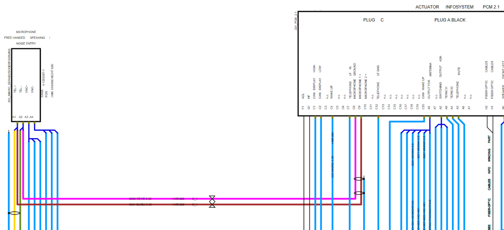
For the OEM MIC, I just had a quick look at the wiring diagrams (I got myself a PIWIS 3 recently and the wiring diagrams are included for the 9X7 cars). It appears that there are 4 connections: TEL+, TEL-, VNC+ and VNC-. The TEL wires goes both to the PHONE module (under passenger seat, NOT next to the NAV module) and to the PCM: plug C, pins C8 & C9, yellow and green wires. I don't know what these VNC wires are, but they go to the BOSE amplifier as per the diagrams. I will definitely check where these wires go when I will be in there.
TEL+ TEL- i think are the wires used for the protocols to pick up + hang up the phone. VNC+ VNC- is for the MIC signal itself (going straight to the PCM) hence plug C8+C9 (red and green wires in the middle image attached - phone module installed in car). I believe it is C8+C9 that needs to be intercepted where we can then use the mic. Thanks for the confirmation.
Originally Posted by leloupgris
For the green wire of the 20pin connector, I only found in the diagrams a green wire that comes from the GATEWAY module and is labelled as CAN wake up (plug C, pin 20), and on the GATEWAY is labelled as "wake up cluster/PCM". So this should be the wake up signal for the PCM. I believe the GPS data is transmitted through the fiber, as on the NAV module there are no wires goig to the PCM except a "wake up" wire.
Got it, now what about pin4 then - that based on the info I found is also a wakeUp signal. Finally can you confirm that pin19 - is for backupCamera (for cayennes). And If so does it send a 200ma signal?
Originally Posted by leloupgris
For the DC extensions, I'll just get some black and red wires that I will solder to the DC plug coming from the camera, and solder everything on the CAMERA harness on the back of the headunit, with some heatshrink. I like solder + heatshrink when possible.
The ONLY area you need to soldier (if you wish) is the at the pcm. The DC plug coming out of the camera will plug right into the DC extension cable - the other end of the DC extension cable (by the pcm) is where u plug in the 2nd half of the camera (DC with 2 wires for splicing). I'm surprised this isnt industry standard but as all the new decks will have an app to access cameras at any time - i suspect this will be.
When you do get around to the project and can access the oem mic, can you take a photo of the plug itself? this will be the key to solving this problem. I can't tell if thats a fakra adapter or not.
Having helped figure out the oem pccm+ rear backup cam (it was meant for the 955s) - on the 997. I made a friend who was kind enough to send me the porsche mostHur adapter as he didnt need it for his askAmp 997.
I took it apart right away (including the harness) to map out all the pins - but i'm inclined to believe based on the wiring diagrams + plus from the circuit board itself - that It is really just a 2 channel unit device with fader emulation + not a true 4 channel unit in any real way.
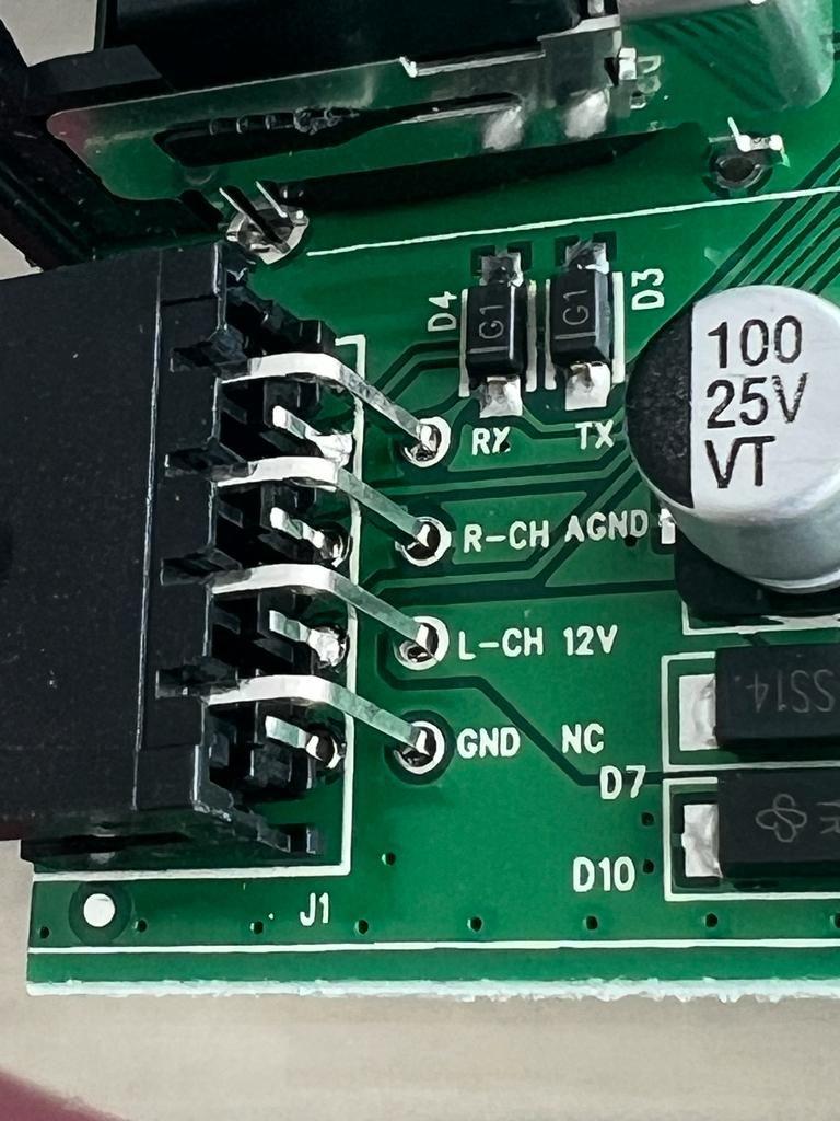
- on the harness , the L+R (white + green) analog audio cables are shielded separately from all the 12V (power + GND) + data (TX,RX) related cables. There is a AGND (analog ground) thick black cable that grounds via wiring in a crissCross a method I havent seen before) - which a portion of those ground cables is partially coiled inside the white + green (L+R) wires. The white + green (L+R) are also individually wrapped (sheilded) and are analog audio outputs no doubt - leading me to believe that the harness design takes enough care to ensure the analog 2 channel L + R signals remain as clean and carefully grounded as possible.
- the fader system I believe is merely 'calculated' via the TX (transmission) + RX (receiver) wires/channels. I believe via these 2 data channels, a front/rear ratio is calculated and hence a fader effect is achieved - via increasing/decreasing the levels on the front/rear channels. Nevertheless the front Right + Rear Rght is still based on the single R channel analog source. Same goes with the left.
Someone with a higher level of electronics can chime in, but I'm pretty sure its just a 2 channel stereo analog audio unit with a fake fader, and not a true 4 channel analog audio unit.
It is essentially a workaround system to retain the fader to function. But by no means are the rear L + R channels separately sourced channels.
TEL+ TEL- i think are the wires used for the protocols to pick up + hang up the phone. VNC+ VNC- is for the MIC signal itself (going straight to the PCM) hence plug C8+C9 (red and green wires in the middle image attached - phone module installed in car). I believe it is C8+C9 that needs to be intercepted where we can then use the mic. Thanks for the confirmation.
Got it, now what about pin4 then - that based on the info I found is also a wakeUp signal. Finally can you confirm that pin19 - is for backupCamera (for cayennes). And If so does it send a 200ma signal?
The ONLY area you need to soldier (if you wish) is the at the pcm. The DC plug coming out of the camera will plug right into the DC extension cable - the other end of the DC extension cable (by the pcm) is where u plug in the 2nd half of the camera (DC with 2 wires for splicing). I'm surprised this isnt industry standard but as all the new decks will have an app to access cameras at any time - i suspect this will be.
When you do get around to the project and can access the oem mic, can you take a photo of the plug itself? this will be the key to solving this problem. I can't tell if thats a fakra adapter or not.
No, TEL are the MIC inputs for the PCM and the PHONE module, see the diagram:
Highlighted yellow and green wires go to the PHONE module, pink and brown on the PCM to C8/C9. The 4 wires that come out of VNC go to the bose AMP, depending on the options and the car (they put on the same diagram all the wires for all the options, so realistically it's only 2 wires in reality). So supposedly, C8/C9 should be the MIC wires and therefore could be used to re-use the OEM mic. I will have to verify if it's not option dependent (for example, if you have the PHONE module, your mic will be connected only to the PHONE module and not to the PCM maybe?).
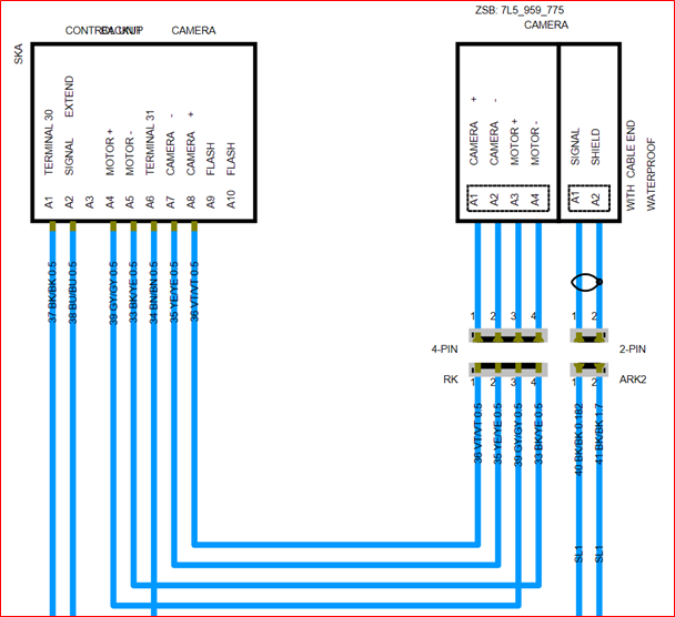
I don't have on hand a pic of the MIC connector you're asking, but on the PIWIS you'll find the diagram of the connector, so it's not a FAKRA:
And here the internal connections of the MIC:
Looks like it's actually two mics in one?
For your question regarding pin C4, it's indeed a wake up wire for the other modules: PHONE, AMP, CD. So it goes like this: GATEWAY wakes up the PCM that in turns wakes up the other modules.
Pin C19 is not occupied on the 997.
For the Cayenne, you have a separate power supply apparently: Camera module on Cayenne
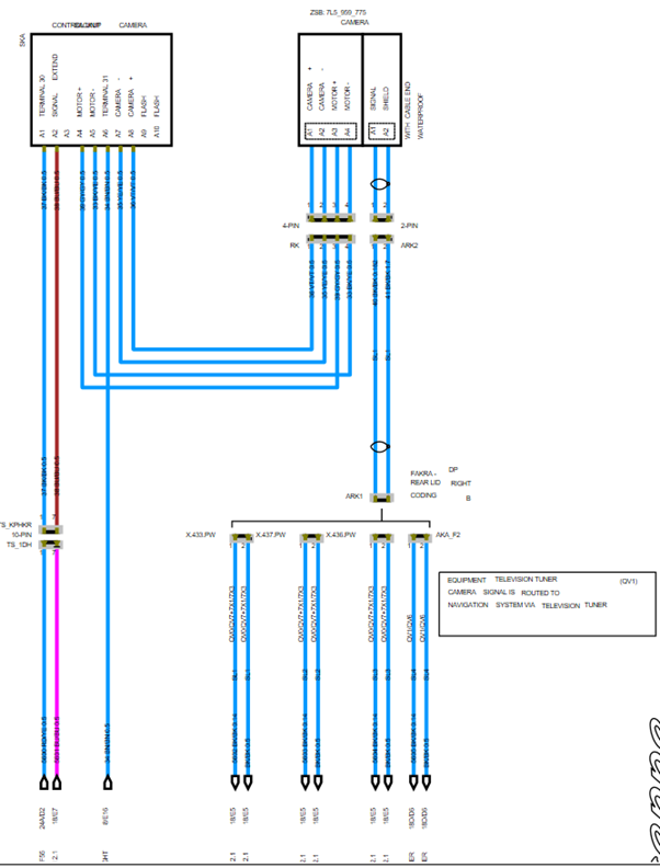
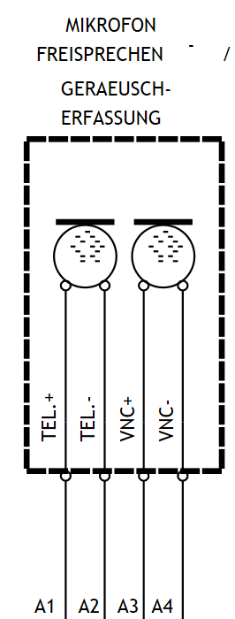
I don't know if you can see properly on this screenshot, but the camera is on the right, and on the left is what powers the camera and its motor (it's labelled "control backup camera", camera is equiped with a motor?).
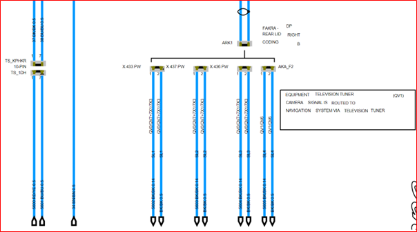
Then this module is conncted to pin C19 on the PCM (highlighted pink wire in the screenshot) and appears to be only a trigger wire (it's labeled "CONTROL CAMERA BACKUP" on the PCM side). Edit: Which means that power to the camera is not through the PCM but via this power supply. The video signal of the camera is then sent to the PCM through a FAKRA connector, unless the car is equipped with a TELEVISION TUNER, in which case it goes to the TUNER and then to the PCM.
Let me know if you need any more info. But I think the PDF of the wiring diagrams of the 997 are available online. It's convenient on the PIWIS because it's interactive.
Last edited by leloupgris; 03-04-2023 at 03:48 PM.
Reason: Added info
TYSM - is there a higher resolution version of this exact image??
Originally Posted by leloupgris
Camera module on Cayenne
I don't know if you can see properly on this screenshot, but the camera is on the right, and on the left is what powers the camera and its motor (it's labelled "control backup camera", camera is equiped with a motor?).
Then this module is conncted to pin C19 on the PCM (highlighted pink wire in the screenshot) and appears to be only a trigger wire (it's labeled "CONTROL CAMERA BACKUP" on the PCM side). Edit: Which means that power to the camera is not through the PCM but via this power supply. The video signal of the camera is then sent to the PCM through a FAKRA connector, unless the car is equipped with a TELEVISION TUNER, in which case it goes to the TUNER and then to the PCM.
Let me know if you need any more info. But I think the PDF of the wiring diagrams of the 997 are available online. It's convenient on the PIWIS because it's interactive.
Ok I think I get it - you a smart man! it is 2 mics in 1. VNC means vehicle Noise Cancellation.
So either the #666 cars have the 2 in 1 mic - and the ones we all have in our cars ... aren't for phone chatting but are for the VNC (ie bose autopilot) related purposes.
Originally Posted by leloupgris
No, TEL are the MIC inputs for the PCM and the PHONE module, see the diagram:
Highlighted yellow and green wires go to the PHONE module, pink and brown on the PCM to C8/C9. The 4 wires that come out of VNC go to the bose AMP, depending on the options and the car (they put on the same diagram all the wires for all the options, so realistically it's only 2 wires in reality). So supposedly, C8/C9 should be the MIC wires and therefore could be used to re-use the OEM mic. I will have to verify if it's not option dependent (for example, if you have the PHONE module, your mic will be connected only to the PHONE module and not to the PCM maybe?).
TYSM - is there a higher resolution version of this exact image??
Edit: Here you go. Sorry but for some reason the PIWIS is not allowing me to print to PDF... So I had to screenshot everything while zoomed. I put it on the attached PDF. Should be good enough.
Edit2: Well, apparently I cannot add a PDF, or at least it doesn't show in my post. So Here are the images:
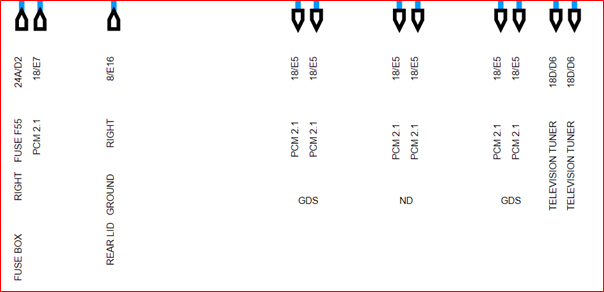
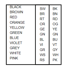
Zoom in on the power supply and the camera zoom in on the 5 wires coming out of the camera and the power supply zoom in on the modules the wires go to Color legend of the wires
Last edited by leloupgris; 03-05-2023 at 11:26 AM.
Reason: Added document
Thank you for this! the Cayenne reverse cam is a silly convoluted thing where there is indeed a motor attached to it.
pin 19 - a control channel pin/wire to the let the camControlModule know that its time to turn the camera on AND turn the camera motor on... got it.
As for Pin19 - does it state what voltage the pcm pushes to this wire to the control channel? is it just a standard 12v?
Originally Posted by leloupgris
Zoom in on the power supply and the camera zoom in on the 5 wires coming out of the camera and the power supply zoom in on the modules the wires go to Color legend of the wires
The camera is on the right, and on the left is what powers the camera and its motor (it's labelled "control backup camera", camera is equiped with a motor?).
Then this module is conncted to pin C19 on the PCM (highlighted pink wire in the screenshot) and appears to be only a trigger wire (it's labeled "CONTROL CAMERA BACKUP" on the PCM side).
Edit: Which means that power to the camera is not through the PCM but via this power supply. The video signal of the camera is then sent to the PCM through a FAKRA connector, unless the car is equipped with a TELEVISION TUNER, in which case it goes to the TUNER and then to the PCM.
Hi All
I have the MYW owTowsin unit, all works great but I have the some questions. I have trawled this thread as best I can but can't find the answers I am looking for. (note I have the 8 +128 Qualcomm unit)
1. The physical button mapping via the Factory Settings menu seem limited to the ROMs apps only (except NAV). I want to map the music symbol button to Spotify or DAB etc... with long and short press, any ideas?
2. Similar to the above, remapping the Nav to WAZE works ok but I want the long press to be Z-LINK for AA, the factory setting only seem to allow Carplay?
3. DAB reception via the window antenna is terrible in motion, can I split the factory antenna for FM and DAB?
4. I have a 997.1 Turbo, tiptronic, how do I route the reverse camera most easily if the rear passenger grommet doesn't work?
1) to confirm, you mean the 6g/128g correct? the 8/128g is only available on the wholeSale/private cheaper units with integrated cpu/mobo. I am putting in a request for android 14 to have this exact function added. Music being defaulted to the Radio app (for music) is pretty much a waste in 2023. I was hoping to MAP to spotify/audible... but the only programmable one is NAV - as you have stated.
2) in my testing, as I dont have an android phone - my testing is only via carplay/Z-link. Feel free to PM me, I can try to work with you on this , and at the very least add this functionally to another version of android OS.
3) unfortunately, I dont have experience in all of the 3rd party developed android modules such as dab+, 360 deg cam etc. This one I would google re android DAB+ units on the european car forums, as the north american owners dont know much about DAB+.
4) for the turboCars, due to the additional side turbo vent makes the reverse camera space to get thru is ALOT tighter. Based on the videos I've seen re rear camera on a turbo, the interior side panel will need to be removed. It wont be as simple as removing the rear panel, feeling things through (minimal visibility) and then having to fish a large zip tie through.
Originally Posted by RLR997
Hi All
I have the MYW owTowsin unit, all works great but I have the some questions. I have trawled this thread as best I can but can't find the answers I am looking for. (note I have the 8 +128 Qualcomm unit)
1. The physical button mapping via the Factory Settings menu seem limited to the ROMs apps only (except NAV). I want to map the music symbol button to Spotify or DAB etc... with long and short press, any ideas?
2. Similar to the above, remapping the Nav to WAZE works ok but I want the long press to be Z-LINK for AA, the factory setting only seem to allow Carplay?
3. DAB reception via the window antenna is terrible in motion, can I split the factory antenna for FM and DAB?
4. I have a 997.1 Turbo, tiptronic, how do I route the reverse camera most easily if the rear passenger grommet doesn't work?

 03-04-2023, 01:43 PM