When you click on links to various merchants on this site and make a purchase, this can result in this site earning a commission. Affiliate programs and affiliations include, but are not limited to, the eBay Partner Network.
Pin 8 - indeed is switched ground and where you should connect the ground for the camera. For powering the camera, I connected to switched 12v from the fuse box. The PCCM+ clearly has an internal 10 second delay power off on this switched ground, so no error message with the camera when shifting out of reverse (keeps power going for 10 seconds)
the trick now is to confirm that the camera is actually OFF, when the the switched ground circuit is open. ive read that the power to these car cams can actually be powering the camera (perhaps the video cable has a video ground, which closes the circuit and powers the camera @ all times??). definitely would want to avoid this.
also great to know that all porsche did with the 6 pin android video harness was - remove the camera power (pin5), and swap the front rca (pin7) with the parking brake signal. they left the ground pin8 exactly as is.
the trick now is to confirm that the camera is actually OFF, when the the switched ground circuit is open. ive read that the power to these car cams can actually be powering the camera (perhaps the video cable has a video ground, which closes the circuit and powers the camera @ all times??). definitely would want to avoid this.
That's why I keep thinking of a relay as a good solution to be closing the circuit with the ACC/12V and not with the ground.
Obviously, the drawback of a relay is that you add one more failure point and for that small amount of current, I don't think you really need it. See when you need a relay.
the trick now is to confirm that the camera is actually OFF, when the the switched ground circuit is open. ive read that the power to these car cams can actually be powering the camera (perhaps the video cable has a video ground, which closes the circuit and powers the camera @ all times??). definitely would want to avoid this.
You're right - I checked and it's 12v all the time (switched ACC anyway). Looks like the relay is coming back into the mix here!
What's the current consensus on making this PCCM+ Apple Carplay wireless? Is it as easy as just buying one of those dongles off Amazon that makes your Carplay wireless? Something like this :
What's the current consensus on making this PCCM+ Apple Carplay wireless? Is it as easy as just buying one of those dongles off Amazon that makes your Carplay wireless? Something like this : https://www.amazon.com/dp/B0B2R7NQ1J...1-df67fc737124
You're right - I checked and it's 12v all the time (switched ACC anyway). Looks like the relay is coming back into the mix here!
Originally Posted by nikandriko
That's why I keep thinking of a relay as a good solution to be closing the circuit with the ACC/12V and not with the ground.
Obviously, the drawback of a relay is that you add one more failure point and for that small amount of current, I don't think you really need it. See when you need a relay.
I'd think using a capacitor and diode would be a simpler solid state solution to creating a delay to the cam's 12v trigger. Less parts and more reliable. 10s delay is too much, especially when it mutes the whole system. 1-2 sec is good if you just want to eliminate the momentary no cam message.
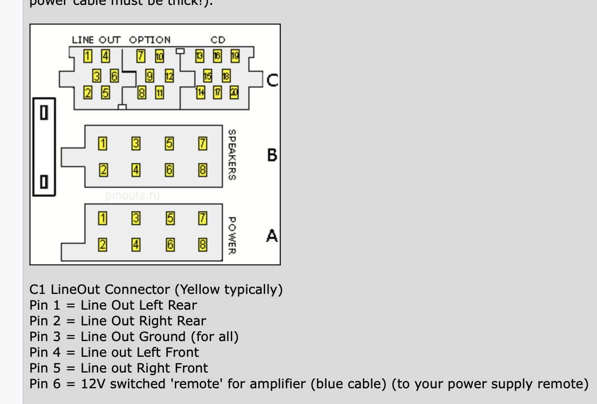
With respect to those who are trying to accommodate an aftermarket amp (non-bose car) I'm wondering if the pin out from an older PCCM unit is the same for the PCCM+ unit:
If they are the same then I could bypass these wires into RCA females to accommodate the line in to the amp. It's frustrating that on aliexpress you can buy the same radio, except for sd card nav , with dedicated RCA amp outs and this unit does not have that option. I suppose porsche felt this is an option for porsches that have not had their audio systems violated .. ?
Going by the pins #s on the above, C2 is currently used for CAN Low Infotainment, and C1 is for CAN High Infotainment. I'm not sure if you can multiplex audio signals with the CAN data. I believe 996 PCCM+ guys tried to convert this section to a line level out but could never figure it out.
I'd think using a capacitor and diode would be a simpler solid state solution to creating a delay to the cam's 12v trigger. Less parts and more reliable. 10s delay is too much, especially when it mutes the whole system. 1-2 sec is good if you just want to eliminate the momentary no cam message.
Love the idea. Is there any off-the-shelf switch off delay timer (integrated) circuit that we can buy off Amazon and waterproof?
I don't know about any off the shelf circuit, but thinking more about it, you just need to keep power to your cam for at least as long as the 'no cam' message is shown on your screen after you disconnect the 12v trigger wire. What is that, 0.5 sec? So, a) you could just wire the cam to stay on as long as the car is on by tapping into a wire somewhere in the back that has 12v. or b) if you powered the cam wire from the reverse light, have the cam stay on long enough for like a 0.5 sec after coming out of reverse. You'd put a capacitor in parallel with the power and ground wire of your cam, which acts like a battery until the cam depletes it. But put a little diode in the wire between the cam and taillight, so the setup doesn't affect the taillight. How much current does your cam consume? Assuming 100ma, perhaps a 10,000uf 16v capacitor will give you a half second, or double the uF value if either you need more time or your cam consumes more current. A capacitor of that value is 16mm x 30mm and about $3 on eBay.
But have you confirmed your cam does not stay on even though you disconnect the ground wire? It could as myw mentioned, pull ground through the RCA video ground.
But have you confirmed your cam does not stay on even though you disconnect the ground wire? It could as myw mentioned, pull ground through the RCA video ground.
With a relay in place, when the triggered ground (pin8) goes OFF, the ACC to the camera should go to 0V. In this setup, I don�t think it matters where the camera gets ground from.
Last edited by nikandriko; 03-18-2023 at 12:39 AM.
Ok understand now, that will work. This is what I was talking about before:
I love the idea and simplicity of this approach. I basically have 2 questions:
Once we get out of reverse, the capacitor starts getting discharged and as the voltage lowers, the camera slowly goes off. Doesn�t this harm the camera in any way? Those mid-voltage operating states?
Does this setup need any waterproofing? Can the capacitor and diode be hanging out there and just be soldered or do they need to be on an integrated waterproofed circuit?
Last edited by nikandriko; 03-18-2023 at 01:15 AM.

 03-17-2023, 01:03 PM