When you click on links to various merchants on this site and make a purchase, this can result in this site earning a commission. Affiliate programs and affiliations include, but are not limited to, the eBay Partner Network.
Just keep in mind that the telephone wiring is on a circuit rated for 7.5 amps. Don't recall off hand what else is on the circuit. I'll take a look at the wiring diagrams.
Thanks, man. The sub *can* run with fewer than 4 amps of current. But I�m planning on using the phone wiring only for the remote turn-on. Not sure what the current draw is there. Hopefully that leaves enough for the phone to charge (doesn�t have to be fast).
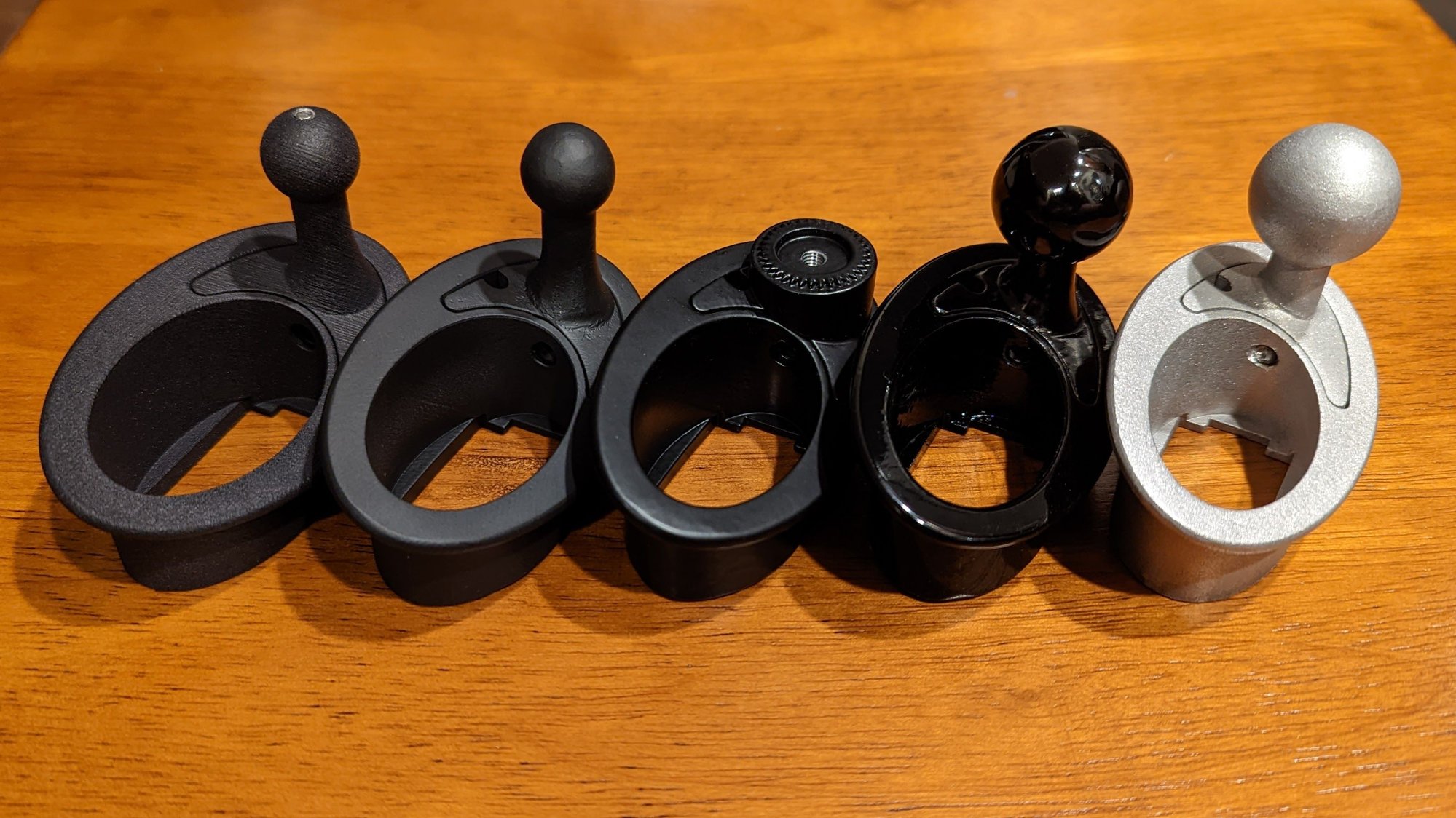
Actually yes. Got back all my finished aluminum parts today. My anodizer had trouble getting the dye to take to the aluminum alloy, so those parts were done in black cerakote instead. Also I won't have the glass bead blasted/clear anodized aluminum version for sale until the next batch. I'll be reaching again to the original purchasers that expressed interest in upgrading to the aluminum version in the next couple days. After I know what quantities are left, I'll make those available on the website. Also planning to add a package deal with the USB/connector.
From left to right: black glass filled nylon, black cerakote aluminum, black matte powder coated aluminum, gloss powder coated aluminum, glass bead blasted aluminum
I got my iphone 14 pro last week, and the enlarged camera area is causing some interference issues with the ESR mag safe charger I have. For reference, there is only about 1/8" of clearance between the bottom of the camera bezel on my Apple magsafe case and the OD of the apple magsafe charger. The ESR mag safe is obviously much larger, and the phone does not always sit flat on the charger unless you align everything perfectly. @yaz996 can you share what the size differences are between the apple magsafer charger and rennline charger?
I got my iphone 14 pro last week, and the enlarged camera area is causing some interference issues with the ESR mag safe charger I have. For reference, there is only about 1/8" of clearance between the bottom of the camera bezel on my Apple magsafe case and the OD of the apple magsafe charger. The ESR mag safe is obviously much larger, and the phone does not always sit flat on the charger unless you align everything perfectly. @yaz996 can you share what the size differences are between the apple magsafer charger and rennline charger?
The Apple brand magsafe charger has a 56mm diameter. Once that is inserted into the RAM B mount adapter that diameter is now 61mm. The ESR magsafe charger has a 60.5mm diameter at the raised circular portion. The Rennline magsafe charger has a 57mm diameter, so that might solve your problem. The Rennline mount isn't as strong as the ESR, but you could try out the one I bought. Shoot me a PM.
Yeah it's pretty different. 986 doesn't actually have a separate trim piece surrounding the hazard switch. The switch itself is larger and asymmetrical to cover up the binnacle screw location.
I do have a 986 binnacle (instrument cluster surround) in my garage to work from. Hopefully have it available within a couple months.
I�ve been looking at how to solve for 986 in the meantime. The hazard light switch really is the perfect spot for a 17mm ball mount.
What about (1) relocating the hazard light control to a standard oval switch in one of the blanks just below? Then (2) fabricate (3D print?) a plate that fits securely into the hole and attach a ball mount to it.
(1) sounds easy, not sure if hidden traps involved
(2) no idea, presumably need good measurements or a sample to work with
any thoughts or advice?
monty
Relocation isn't necessary, but definitely a more complex project due to the geometries, constraints, and other details like screw holding the binnacle to dash being located on the cavity centerline. Figured it was good excuse to add a 3D scanner to my tool kit.
Im not sure I understand the 4 choices for the power USB module. The last 2 choices are cutoff!
I'm not a marketing guy, so my product descriptions and buzzwords could use some work. First two options are the basic telephone wiring connector to USB power module with a choice between switched and always-on power. The other two options just provide the additional leads to make use of the power not used by the USB module. Here's a couple pics:
Basic option: telephone wiring connector to USB power module. The version seen here is on switched power, and the always-on power connection is unused. Dual option: telephone wiring connector to both USB power module and extra leads. In the version seen here, the USB power module is always on, and switched power can be provided to another accessory.
Nice!
I'm also looking to upgrade from my early 3D printed mount to a black cerakote aluminum. I wasn't going to, but those look nice!
I'll also be getting switched power USB connector (with the always on wires). Those look really well done.
Nice!
I'm also looking to upgrade from my early 3D printed mount to a black cerakote aluminum. I wasn't going to, but those look nice!
I'll also be getting switched power USB connector (with the always on wires). Those look really well done.
Thanks. Making everything to the same standard that I do for mine own vehicles.
I'd encourage anyone placing an order to include their Rennlist user name. Helpful for me for make that connection.
 09-11-2022, 06:47 PM