When you click on links to various merchants on this site and make a purchase, this can result in this site earning a commission. Affiliate programs and affiliations include, but are not limited to, the eBay Partner Network.
Thank you for the install manual so glad you found it. My 996 is a 2000, not MOST system, but analog. So when taking the PCM out to replace with PCCM+ I am hoping that 996.642.587.00 ground wire to the amp
in pin 17 will do the trick...cause I ain't got sound now, even with the Volume setting CAN to AMP. Again, my system does not have the brown ISO B speakers wires connector from the old PCM 1. will let you know what happens. One would think this cool upgrade by Porsche PCM1 to PCCM+ would be all plug and play! Almost. I will also try to call Porsche but my Porsche service depts up here in New Hampshire are weak. They didn't even know what a PCCM+ is. I will have to call Boston dealers. thanks... for now sitting on a useless $1300 piece of Porsche electronics
There could be rewiring required at the ISO plug. My unit came with two new ISO connectors and pins. Nowhere in the installation documents does it show or mention what the two new ISO connectors are supposed to be used for.
There could be rewiring required at the ISO plug. My unit came with two new ISO connectors and pins. Nowhere in the installation documents does it show or mention what the two new ISO connectors are supposed to be used for.
That's definitely a possibility. But without confirmation via a TSB from Porsche, the PCCM+ could or could not output LINE LEVEL from the YELLOW C1 plug as legacy Porsche Becker units. We don't know.
However, it very plausible that the B connector on the PCCM+ is used in both applications - 1. For base analog systems withOUT a frunk amplifier and, 2. For HiFi analog systems that feed a LINE LEVEL signal to the amp. If the default is SPEAKER LEVEL from the B connection, there should be a way in the menu to lower the signal voltage feeding the amp. Unfortunately, if none can be found, the only work-around will be a HI/LO signal conversion through an ISO wire harness/adapter.
yes my kit also came with the brown B and black A connector kits, which I have to believe is just there as an option if needed
to wire the A B connectors directly yourself maybe in another vehicle. meanwhile I'm waiting on my ground wire and hoping
that solves the problem. I may just ground it myself without the porsche official part
Please take pictures of installing this ground wire and report back! Would like to know if this is something I need to do as well.
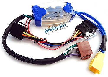
@b3freak I received that HI/LO harness today in the mail, but I am pretty sure it is the wrong one. Here is a picture of what I received:
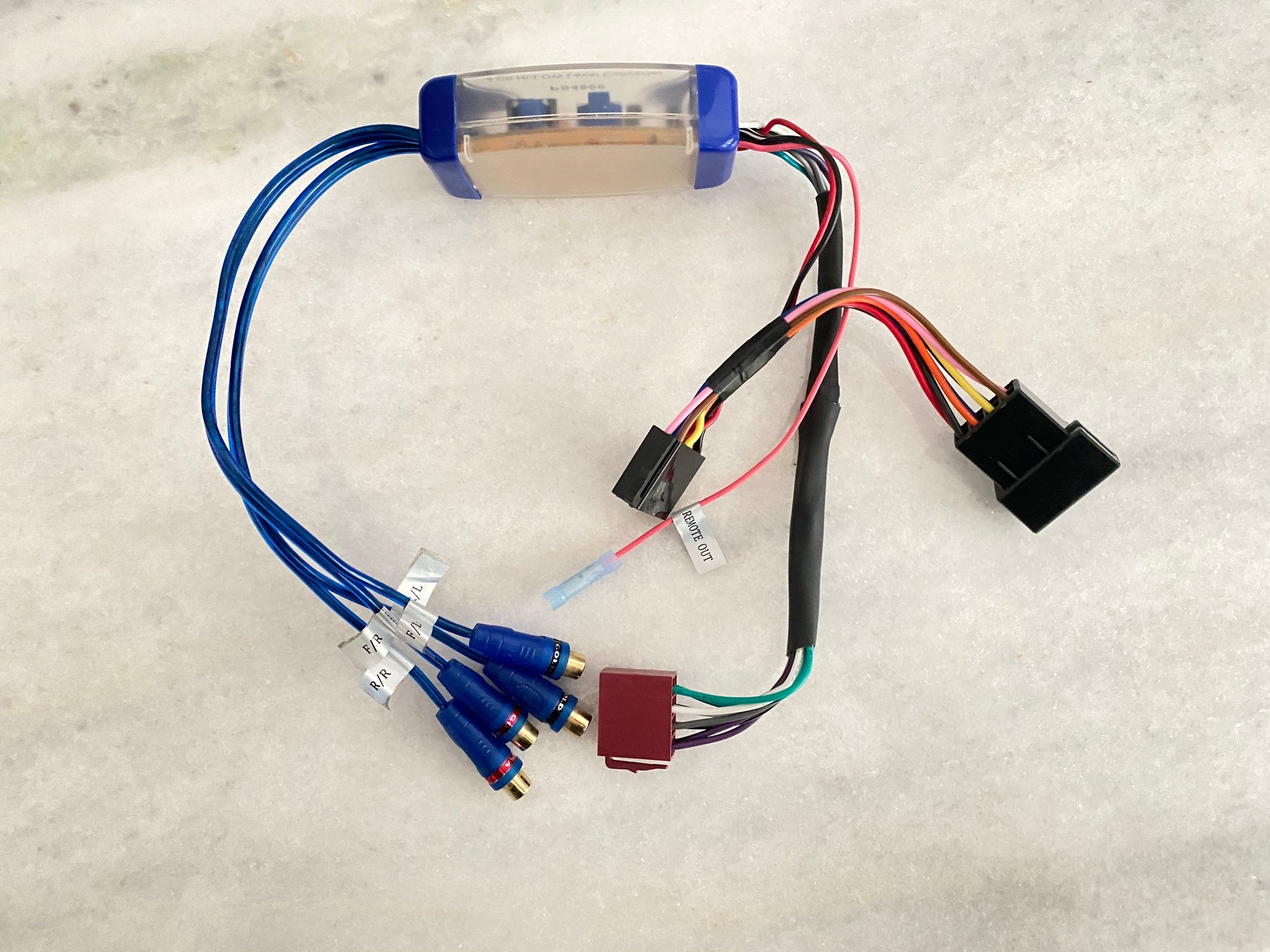
Sorry man. I'm afraid you received the wrong harness. That one looks like the harness for using an aftermarket amplifier. It should look like the second picture with the Yellow C1 plug. Basically, you plug the female black A connector and the female brown B connector from the Hi/Lo harness into the PCCM+ and then, connect the car's female black A connector into the Male A connector on the harness. Next, you connect the male Yellow C1 plug from the harness to the car's Yellow C1 female connector.
As a side note, the ONLY thing different between the one you received and the correct one, is the Yellow plug. Instead of RCA outputs, those connections would feed the lines from the Yellow plug. The ones you spliced back together.
Last edited by ZuffenZeus; 10-22-2020 at 07:10 PM.
Sorry man. I'm afraid you received the wrong harness. That one looks like the harness for using an aftermarket amplifier. It should look like the second picture with the Yellow C1 plug. Basically, you plug the female black A connector and the female brown B connector from the Hi/Lo harness into the PCCM+ and then, connect the car's female black A connector into the Male A connector on the harness. Next, you connect the male Yellow C1 plug from the harness to the car's Yellow C1 female connector.
As a side note, the ONLY thing different between the one you received and the correct one, is the Yellow plug. Instead of RCA outputs, those connections would feed the lines from the Yellow plug. The ones you spliced back together.
I was afraid of that... Still haven�t heard back from the customer service dept for that site. Any idea which option I need to get the yellow/black/brown connector trinity? Or do you happen to know of have another site that might carry the correct harness?
Thank you so much for leading me to his thread--so glad someone got it to work!
Do you have any experience mounting grounding lines like what is being described in the manual? I've never fitted one before, but I'm confident in my instruction-following abilities. I've looked up the PN for the ground line Porsche lists, but it's weeks out from delivery. Can I buy any generic ground line from an autoparts shop? I'm curious where the ground line goes from pin #17--does it just go directly to the bolt/washer in the Figure 15.5 in the manual?
So I was impatient to wait 8 week delivery of an official Porsche part grounding wire. I don�t have a pic of the final result. But let me describe what I did: take off the black 18 pin connector from the amp interface. Then you have to open it up gently which requires sliding off a harness housing small cover. Then the interface with all the pins slides out from the harness. Locate pin 17, next to pin 18 which is actually labeled (you might need to magnify its so small). Take a needle nose plier and grip the base of the red black yellow (arguably green) wire and slightly pull out while at the same time pushing in on the metal end on a little nub which releases the pin from its harness. Now cut that wire giving you about three inches. That was the dsp connector no longer needed. Take another similar guage wire about 10 inches long so that it can reach the grounding post conveniently located about 8 inches from the amp interfaces, and solder or clip securely with the correct guage wire connector to the 3 inch pin wire. Call it Porsche part no. 996.ididitmyselfgroundwire.
now insert the pin back into pin slot 17, put the harness back together, and attach the ground end to the post. Btw I would do all this with the battery disconnected to be safe. And if you have the PCcm unit CAN parameter set to AMP(see instructions in this thread earlier), you should now have sound. Pin 17 wire of AMP black 18 pin harness connector
Ok, so I am essentially crimping the exposed wiring of the ground line to the cut end of the pin #17 wire, then placing pin #17 back into its home, and then securing the other end of the ground line to the conveniently-located grounding post?
Ok, so I am essentially crimping the exposed wiring of the ground line to the cut end of the pin #17 wire, then placing pin #17 back into its home, and then securing the other end of the ground line to the conveniently-located grounding post?
If you're going to re-use the no. 17 black/red/yellow wire coming from the 18-pin connector, then you DON'T need to remove it from the connector to make your ground wire like Paul. Just cut it about 3-4 inches back from the connector. Then, splice another 10-inch piece of wire to the no. 17 black/red/yellow wire coming from the connector.
Once spliced, connect the new no. 17 line to the proper ground point noted in the TSB. Make sense?
Make sure you shield the end of the cut original no.17 cable in the wire bundle.
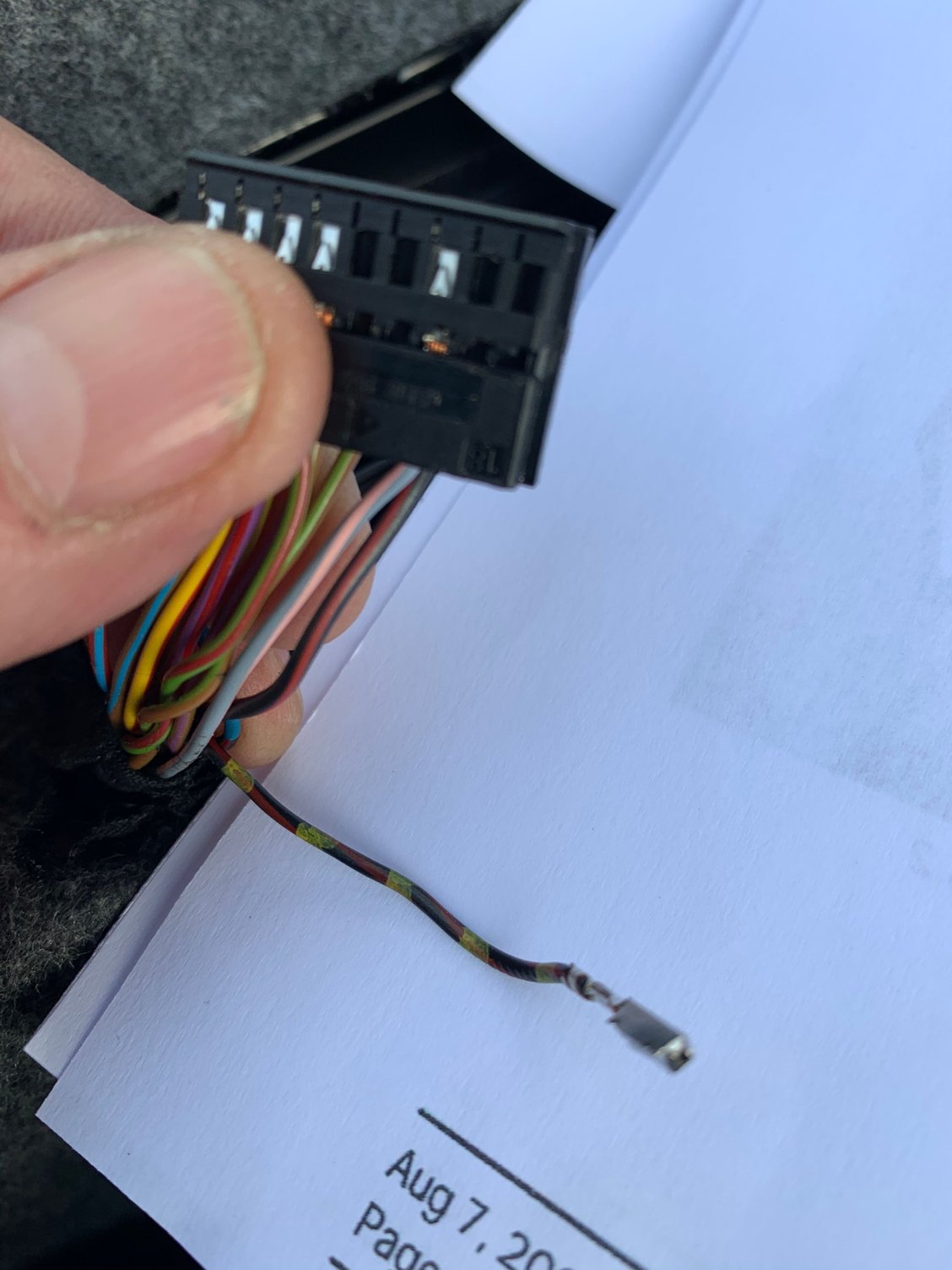
And so the mystery deepens. I opened the black housing connected to the Amp to find that pin #17 is empty... These are just the 8 speaker wires + 12V wire that I spliced into the yellow C1 connector at the other end of my head unit.
Other than waiting for that correct hi/low harness to arrive I do not know what to do from here. Anyone have suggestions?
Do you have any means to test the amplifier to confirm that it's functioning correctly with clean audio to the speakers? I would hate to think all this work and investigation on the PCCM+ and wiring side is in vane. Seems like others have posted success with integrating the PCCM+ into older analog systems like yours. In the Porsche TSB, they mention that 12V switched is routed via pin#6 on the Yellow C1 plug of the PCCM+ and so that tells me that it has a purpose for these analog systems. But I'm not sure what more I could offer you. Sorry.
Well, I know according to the Porsche TSB that pin 17 was for the DSP. Maybe you don't have a DSP. I would try to ground
that pin 17 slot anyway and see what happens. Worth a try. You might have an extra pin from your PCCM kit?

 10-20-2020, 04:58 PM