When you click on links to various merchants on this site and make a purchase, this can result in this site earning a commission. Affiliate programs and affiliations include, but are not limited to, the eBay Partner Network.
Fitting ground line: On vehicles
(1997�2001) with M662 (PCM
generation 1) and M680 (Digital
sound package), an additional
ground line 996.642.587.00 must be routed to the amplifier. So, if you have this setup, you will need the additional ground line.
Here is a picture of my options sticker. Correct me if I am wrong, but I do not see M662 or M680.
Also, is there anything else to do to reset the PCCM+ unit besides turning the car off after changing the setting to Amp?
Remove/connect the negative battery terminal
It looks like you have a standard CR220 radio. Is your amplifier standard Porsche in your car, or is it aftermarket?
VIN WP0AA299XXS627057 Model Carrera Coupe 996 Date of production 01.07.1999 Model year 1999 Sales type 996110 Engine Code 9601 Transmission Code G9600 Axle drive 6S Equipment BF Roof color K3 Carpet color code B50 Exterior color / Paint Code K3 / 40W Seat combination no. EGJ Number of Z-Orders 1
032 Touring suspension 058 Impact absorbers, front and rear 130 Control and indications in English lettering 197 Stronger battery 218 Licence plate holder version 4 219 Differential 270 Door mirror -flat- driver's side, electrically adjustable and heatable 273 Door mirrors, electrically adjustable and heatable 274 Vanity mirror illuminated 335 Automatic seat belt, 3-point, rear 338 Rear-wheel drive 369 Standard seat, left 370 Standard seat, right 424 CD storage unit 436 3-spoke airbag steering wheel 441 radiopreinstallation 446 Concave wheel centers with full-colour Porsche Crest 454 Automatic speed control 465 Rear foglamp, left 480 6-speed manual transmission 484 Version for USA 490 -MY 01 sound system MY 02 sound system Harmann analog 535 Anti-theft lock 315 MHz 539 Mechanical seat-height adjustment, left 540 Mechanical seat-height adjustment, right 553 Version for USA, Canada 562 Airbag, driver's side and front passenger's side 563 Side airbag 566 Front fog lights, white 567 Windscreen tinted, upper part darker coloured 573 Air conditioner 581 Center console, front 590 Power lid locking 602 Center high-mounted stop lamp 650 Electrical sliding roof 651 Electric window opener 657 Power steering 660 Obd 2 661 Stricter emission-control concept 685 Rear seats, split 696 CD radio "Porsche CDR 220" 936 Seat covers, rear, leather 981 Leather equipment without seat covers 983 Seat covers, front, leather X71 Instrument dial painted/Aluminium Look finish X97 Gear lever **** in aluminium/leather X98 Handbrake lever in aluminium/leather XJ4 Leather cover for ignition lock surround XKL Leather speaker covers XME Rear section of centre console painted XN3 Dashboard side air vent in leather XNG Instrument surround in leather XNN Center air vent bracket in leather XNU Leather trim strip (dashboard) XRL 18-inch SportDesign wheel XV1 Defroster trim in leather Codes With No Description 236
426
434
912
E70
Y06
thank you!
As far as I can tell the amp is original to the car. I did not remove it, it I could see that it says �Haes� and has a part number that begins with 996.
So what should my next step(s) be to get sound pumping through the speakers?
Did you ever do anything with the red/black wire? That's the wire that tells the amp to turn on. It needs to have 12V applied when the radio is on.
So, answer me this: is there a white wire attached to the black plug A in slot #5? If there is that is the signal to turn on the radio antenna. I would tap the black/red wire into that white wire, if it exists. You will want to have both the white and black/red wire hooked up or you will get no radio reception.
So, answer me this: is there a white wire attached to the black plug A in slot #5? If there is that is the signal to turn on the radio antenna. I would tap the black/red wire into that white wire, if it exists. You will want to have both the white and black/red wire hooked up or you will get no radio reception.
Haven�t done anything to the red/black wire yet as I am waiting for instruction as to what exactly I need to do with it.
I just checked�there is a white wire in the #5 slot (assuming I am counting the slot numbers correctly). Regardless of the count, there is only one solid white wire in that entire space.
So, all I need to do is strip part of the insulation from the white wire to expose some of the wire and then wrap the red/black wire around the part I just exposed? Is there a better way to splice these wires together?
Also, is there anything else to do to reset the PCCM+ unit besides turning the car off after changing the setting to Amp?
Let's all take a DEEP breath!
I may be able to help. I can't reach through the computer, but maybe I can get you into the RIGHT frame of mind. I've personally installed aftermarket radios on both analog (like yours) Porsche 996 as well as a MOST based 996.
Here's what you MUST do to make this new system happen:
FIRST - You must THINK like the engineer that designed the ORIGINAL Porsche/Becker/HAES system in your car and work backward to find out what is missing and what you need to complete the new PCCM system.
You have the earliest analogy HiFI systems.
That is, your car had a CR220 Becker radio that FED a 4-channel line level audio signal(s) to the HAES amp in the frunk. Then, the amp's speaker level output fed the 6 speakers in your car. (dash, door, and rear)
It appears that the previous owner cut the YELLOW C1 connector NOT... That's NOT the B-connector. I repeat, IMHO... that's NOT the B connector that was cut off.
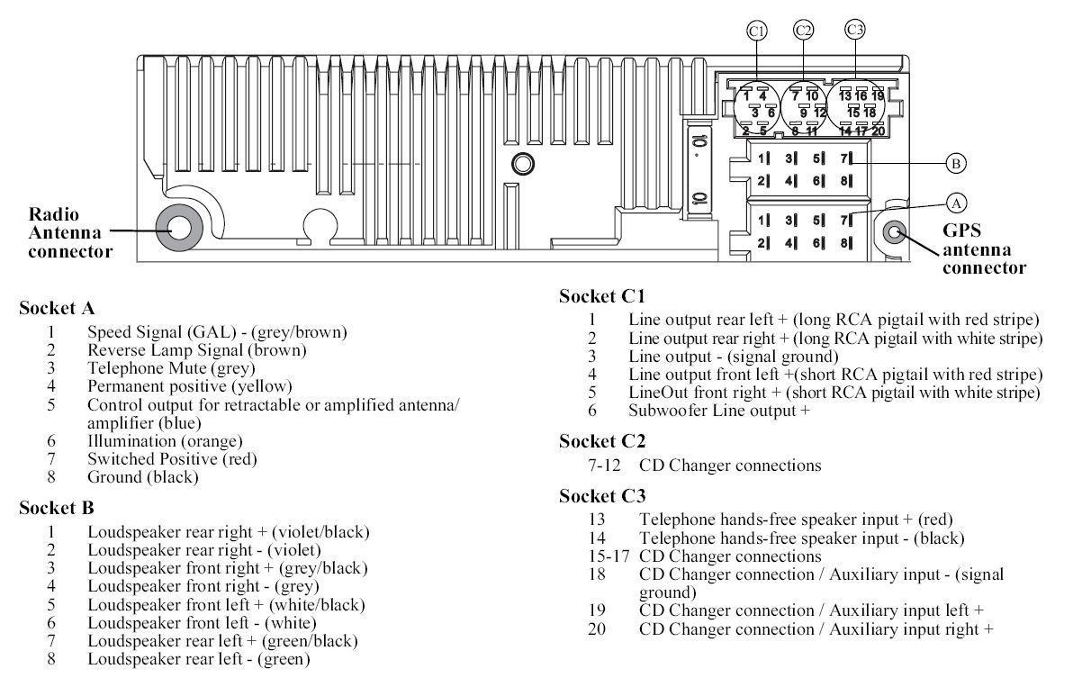
Look at the diagram....
In your radio setup, the Headunit was NOT used to power the speakers. (notice outputs on diagram) Therefore, there was NOT a B connector. In some base cars, the B connector would have been used to output to the speakers for sound. In your case, it was not used.
Instead, the C1 connector was used to output to the AMP in the frunk. Then the output from the amp powers the speakers.
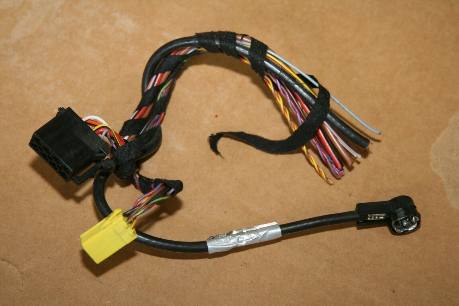
Here this is an old wiring harness pulled from a '99 Porsche Becker/HAES system like yours...
Notice anything in particular? Look at the C1 yellow connector. Notice the lines that look similar to yours?
IMHO, those are the audio line level outputs to GO TO the amp. These lines are NOT meant to be connected to a speaker level output on your PCCM.
Now, I'll stop right here so that you can examine what I've offered.
Last edited by ZuffenZeus; 10-04-2020 at 11:47 AM.
It appears that the previous owner cut the YELLOW C1 connector NOT... That's NOT the B-connector. I repeat, IMHO... that's NOT the B connector that was cut off.
Look at the diagram....
In your radio setup, the Headunit was NOT used to power the speakers. (notice outputs on diagram) Therefore, there was NOT a B connector. In some base cars, the B connector would have been used to output to the speakers for sound. In your case, it was not used.
Instead, the C1 connector was used to output to the AMP in the frunk. Then the output from the amp powers the speakers.
Here this is an old wiring harness pulled from a '99 Porsche Becker/HAES system like yours...
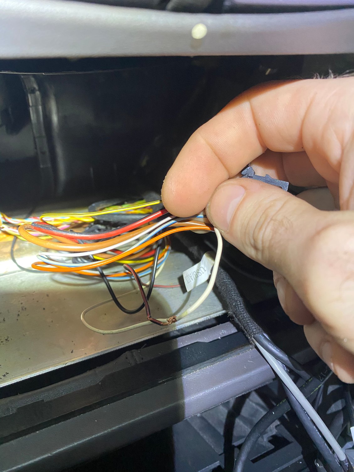
I am totally willing to accept that the C1 connector is the direction that I need to take in order to remedy this problem, but the reason I didn't go that route initially was due to the wiring that existed when I removed the aftermarket radio. Looking at the original picture I posted to start this thread there are 4 pairs of pigtail wires and a lone red/black wire, which makes a total of 9 wires. The C1 connector can only accept 6 wires. What do I do with the other wires, and what do I do with the re/black wire? If it powers amp, what do I need to splice it into so it receives power?
Haven’t done anything to the red/black wire yet as I am waiting for instruction as to what exactly I need to do with it.
I just checked—there is a white wire in the #5 slot (assuming I am counting the slot numbers correctly). Regardless of the count, there is only one solid white wire in that entire space.
So, all I need to do is strip part of the insulation from the white wire to expose some of the wire and then wrap the red/black wire around the part I just exposed? Is there a better way to splice these wires together?
You need to connect the red/black wire to a 12V line that is live when the radio is on. The white wire in the Plug A position 5 provides this. The pin numbers are molded into the plug or you can google up "DIN Radio Plug" to get a picture showing the positions.
So, yes, splice the red/black wire into the white wire AFTER you check it's going to position 5 on plug A.
Make sure your PCM+ is set to Line Output or you will get mega distortion by overdriving the amp inputs. I don't know how to do this, it was listed earlier in this thread.
I'm not responsible if this doesn't work. I *believe* this to be correct.
I am totally willing to accept that the C1 connector is the direction that I need to take in order to remedy this problem, but the reason I didn't go that route initially was due to the wiring that existed when I removed the aftermarket radio. Looking at the original picture I posted to start this thread there are 4 pairs of pigtail wires and a lone red/black wire, which makes a total of 9 wires. The C1 connector can only accept 6 wires. What do I do with the other wires, and what do I do with the re/black wire? If it powers amp, what do I need to splice it into so it receives power?
First, go to the frunk and take a picture of the two multipin cables connected to the HAES amp. Make sure you get a CLEAR picture of all colored cables! Unbolt the amp bracket so that you can remove the amp for the picture.
This will help! I promise you.
Here's a picture of the two connectors.
Last edited by ZuffenZeus; 10-04-2020 at 02:56 PM.
I have depart for a time, but I'll check in later.
This is important...
It's my understanding that Porsche assumes that you are installing the PCCM+ system in an "unmolested" OEM legacy Porsche audio system. Therefore, it needs to be put back to a baseline (i.e. stock) before moving forward.
Until we get to that point, it will be a bumpy road. After that... smooooooth sailing!
I spliced the red/black wire into the white wire and wrapped the connection with electrical tape.
I NOW HAVE SOUND through the speakers. However, I am getting quite a bit of feedback (car on, engine off) and the volume is quite loud even when set to a very low volume level. Do I need a ground loop isolator, or do I need to make a new ground? I tried to attach a video of the sound to this post, but am having difficulty.
Originally Posted by b3freak
First, go to the frunk and take a picture of the two multipin cables connected to the HAES amp. Make sure you get a CLEAR picture of all colored cables! Unbolt the amp bracket so that you can remove the amp for the picture.
I saw this after I spliced the wires, unfortunately. I will get a picture of the connectors and update.
 10-03-2020, 04:39 PM