When you click on links to various merchants on this site and make a purchase, this can result in this site earning a commission. Affiliate programs and affiliations include, but are not limited to, the eBay Partner Network.
I fee like a broken record here, but I will repeat again: THERE ARE NO INSTALLATION INSTRUCTIONS. There are are no diagrams stating what the various connections at the back of the unit do. There is a manual that informs you how to work through Apple CarPlay, and change the color of the buttons, but that�s about it. Porsche really intended this to be installed by a professional it seems.
I will provide a picture of the Amp later this afternoon.
I'm trying to be nice here, because you seem like you've gotten yourself in a mess, but STOP with the attitude or you're on your own!!! Period. You've posted to several threads and I'm not going to comb through every post and thread you're apart of. If you don't want my help, fine; I have better things to do with my time.
THERE ARE NO INSTALLATION INSTRUCTIONS. There are are no diagrams stating what the various connections at the back of the unit do.
(see attached image) Are you telling me that within these three Porsche books (red arrow) are not installation instructions of any kind? What are they?
Ok. I think I�ve put it all together now. The photo from b3phreak is the key.
OP: I agree that you need to get those loose wires back into a yellow connector. All 9 of them. Once you do, you should be able to plug it directly into the back of the new head unit.
I found this photo on a different post. But compare the connector slot that�s closest to the edge with the photo that B3phreak posted. I bet the yellow plug goes in the position closest to the screen.
you might be able to get a salavager or someone with a parts car to cut off the yellow connector with some wires attached to make a pigtail that you can crimp or solder onto the loose wires from your dash.
Ok. I think I’ve put it all together now. The photo from b3phreak is the key.
OP: I agree that you need to get those loose wires back into a yellow connector. All 9 of them. Once you do, you should be able to plug it directly into the back of the new head unit.
I found this photo on a different post. But compare the connector slot that’s closest to the edge with the photo that B3phreak posted. I bet the yellow plug goes in the position closest to the screen.
you might be able to get a salavager or someone with a parts car to cut off the yellow connector with some wires attached to make a pigtail that you can crimp or solder onto the loose wires from your dash.
Yay!!! Now you're thinking right. Hopefully we'll convence the OP to do the same.
On an "all-in-wonder" radio system like the Porsche PCCM+, you have to think about the marketing and engineering behind such a device. Think about it... Porsche wants to sell as many of these thing as possible. And they learned that from the last Classic Porsche radio for the 993. With this system, they've gone a step beyond anything before. That is, they've made this ONE unit serve many cars and options - both MOST and Analog OE setups.
There was a tremendous amount of electronic innovations from the beginning of the Boxster in 1997 and the end of the 996 in 2005. Porsche has really thought this thing through.
But that means you have to think like they designed it. That is, they're not wanting you try to integrate the system with aftermarket components. They're expecting the system replaces a factory setup and that includes the original wiring harnesses and connectors. Therefore, it's in the best interest of the OP to return the legacy analog back to the original state or baseline. From there, it will be easier to install the newer unit.
It appears he's hard wired the speaker-level output of the new PCCM+ unit to the line-level inputs of the existing HAES amplifier. He needs to look through the manual and identify how the unit intergrates with older analogy systems. More than likely, the connection you pointed out could be the exact LINE-LEVEL outputs he needs to connect to his existing amp. That's my bet.
There is NO need to use an aftermarket in-line SPEAKER-TO-LINE level converter if the Porsche PCCM will provide clean LINE LEVEL output. Converting SPEAKER LEVEL OUTPUT to LINE LEVEL is always risky because it could induce distortion and hum in the audio signal.
I just wish the Porsche PCCM installation manuals were available in pdf form. This would be a big help to others that are attempting to do the same.
Last edited by ZuffenZeus; 10-06-2020 at 11:52 AM.
I wish that I could help this fellow more, doing electrical work from a distance is very hard.
So, a couple things.
The yellow mini-ISO plug is used in all German cars, VW AUDI BMW Porsche Mercedes and in many other Euro cars. You should be able to get premade harnesses at audio stores.
All modern VW/AUDI radios provide switchable line/speaker level outputs on the brown ISO plug. This has been since the late 90's, perhaps back as far as 1995. To switch between line & speaker you need the VW/AUDI equivalent of Durametric which is VCDS (formerly VagCom).
The 9 wires in the OP's car do not match any Porsche wiring diagram I have.
The regular frunk mounted amp uses a five wire line level connection: four channels plus one common ground. The OP seems to have an eight wire connection: four channels plus individual grounds. There is a higher end amp that uses an eight-wire line level connection.
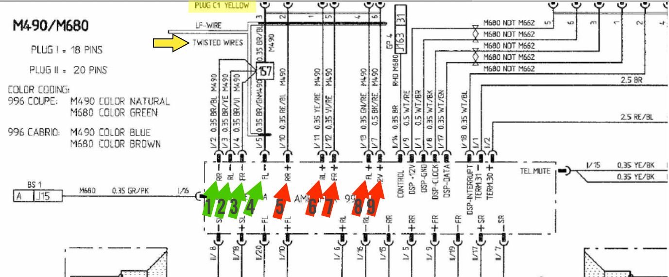
Just to show that I'm not insane I have attached two different wiring diagrams for different MY2002 996 audio options that include amplifiers in the frunk. Pg13A is the five wire via the yellow mini ISO plug. Pg 13B is the eight wire via the brown "speaker" plug.
Just to show that I'm not insane I have attached two different wiring diagrams for different MY2002 996 audio options that include amplifiers in the frunk. Pg13A is the five wire via the yellow mini ISO plug. Pg 13B is the eight wire via the brown "speaker" plug.
Nice! This is a better schematic than I have in my shop manual. We established that he doesn't have the Bose system. Therefore, it's the "Harmann" Becker analog system with the M490 HAES amplifier.
Could you please post a clearer picture of the cable colors? In other words, frame grab a zoomed in image of the left quadrant and then same for the right quadrant. We need to help him line up the colors with what's on the schematic. We definitely don't want him shooting both feet if he choses to take our advice and reconnect the original Porsche YELLOW connector.
After seeing this schematic and the "9 cables" he mentions, makes me wonder if the car had the Porsche CD changer added which would mean the additional GREEN and BLUE connectors.
Last edited by ZuffenZeus; 10-06-2020 at 11:49 AM.
Could you please post a clearer picture of the cable colors? In other words, frame grab a zoomed in image of the left quadrant and then same for the right quadrant. We need to help him line up the colors with what's on the schematic. We definitely don't want him shooting both feet if he choses to take our advice and reconnect the original Porsche YELLOW connector.
His color codes don't match with any schematics I have.
I wish that I could help this fellow more, doing electrical work from a distance is very hard.
This. I was trying to help because my car had a poorly installed aftermarket head unit from the previous owner and I know how frustrating it can be to sort that out.
I eventually fixed my own issue but I�m afraid I�m doing more harm than good here. So, I�m going to defer to more knowledgeable people on the thread. I wish the OP good luck - it looks like it will be great once you have it wired up!
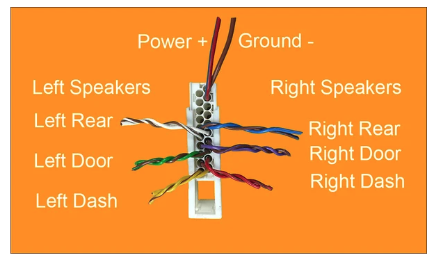
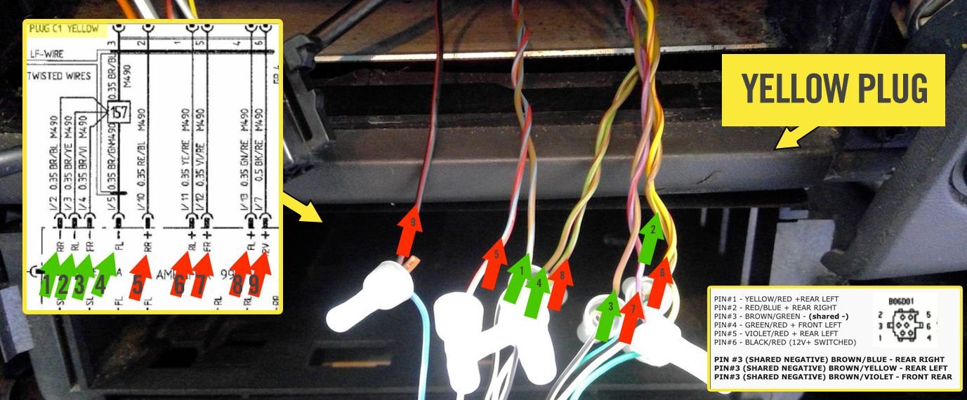
I believe I've found what the OP's 9 wires that he's been referring to. They are 4 TWISTED PAIRS and a 12V+ switched line! If you count them (see numbered) you come out at 9 wires.
I've been away from the computer since my last post. Think through what I've trying to tell you. Don't get wound up trying to count wires. Many connectors will have + and - lines that are shared with other connectors. For example, the YELLOW C1 connector would have 5 + line outputs and one negative. In the case, the original OEM YELLOW C1 shares cables with the original BLACK A1 connector. If you really want the easy route IMHO... then that means you need to get the wires and connections BACK to a BASELINE. Removed the HAES amp in the frunk and POST a picture of the amp's connectors and wires like I requested. Trace those cables BACK to the head unit. Confirm that NONE are missing. Solder the missing original OEM Becker YELLOW C1 connector to the cut lines. Looks like you're missing the YELLOW connector. You should purchase one IMHO. Once the cables are returned to the original factory setup, then I would move forward with installing the PCCM. I don't have access to the installation manuals for the new PCCM and so I'm working blind here unless you can post pdf documents if they're available.
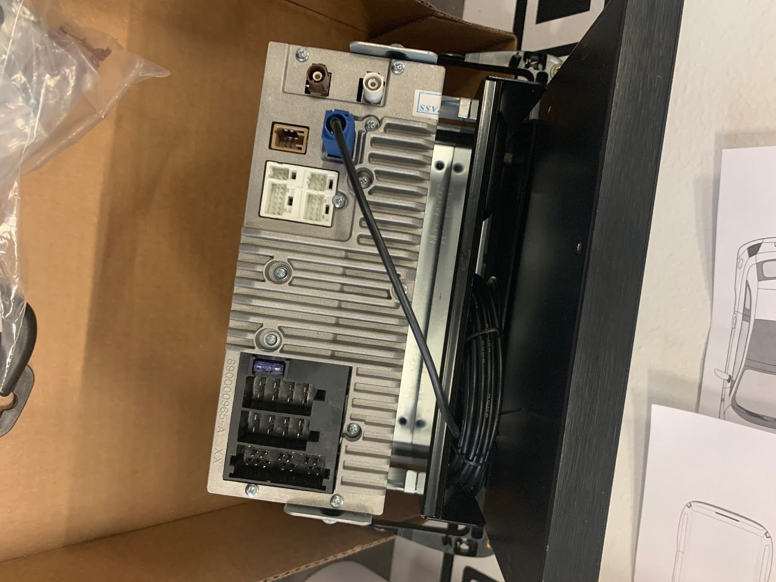
Once you remove the amp for the mount, you'll notice you have two connectors (as shown in the image in my previous post).
The large white connector is the SPEAKER LEVEL outputs from the amp; PLUS, the 12V+ and - that come from the car's fuse box. The smaller black connector on the amp, is for the LINE LEVEL inputs, and 12V remote from the head unit.
I have the amp pictures!
Will read the above posts now to see what I missed over the past couple of days.
(see attached image) Are you telling me that within these three Porsche books (red arrow) are not installation instructions of any kind? What are they?
I assure you none of the included literature in the PCCM+ provides any sort of installation instructions. It doesn't even tell you how to assemble the halo bracket, or even what all the included parts do. I can upload a picture of each page of the booklets, but it would be pointless. They are manuals to guide using the radio and all of its functions, rather than how to install the unit into the car.
Exactly as I stated. The "natural" white multipin plug is your SPEAKER-LEVEL outputs that connects directly to the speakers in the dash, doors, and rear. The BLACK plug should have the 9 wires you located under the dash which originally went to the YELLOW connector that is missing.
Basically, as it stands, you're sending the wrong output from the PCCM to the input of the amp. You should really consider getting a used YELLOW connector on eBay and rewire the cut OEM lines back correctly before proceeding with installing the PCCM+ unit.
Here you go... for just $30.00 here is the correct plug, IMHO. Remember, they made different wiring versions of the YELLOW plug. You need the YELLOW plug that corresponds to the Porsche Harmann analogy HIFI system.
I can't be absolute, but judging from the pictures, the YELLOW plug in this eBay auction appears to have all the 9 lines you need to get your OE system back to stock.
Once you re-wire the replacement YELLOW correctly to the 9 cut wires, then you connect the YELLOW plug to the PCCM. When it's switched to AMP mode, the unit should output LINE LEVEL signals to the amp.
 10-05-2020, 12:12 PM
 You've posted to several threads and I'm not going to comb through every post and thread you're apart of. If you don't want my help, fine; I have better things to do with my time.