
968 Supercharger Kit Development
 08-02-2010, 05:02 PM
#736
Nordschleife Master
Guess I better get to the drawing board and come up with a solution since I have the same setup. I wonder if it would be worthwhile to add a pulley in place of the ac, this would allow for more tension travel.
 08-02-2010, 07:06 PM
#737
Developer
Thread Starter
I think you are on the right track.
Unfortunately I do not have an AC-delete 968 here to test-fit an idler to, so I cannot help you.
The belt, when tightened tight enough, should deflect about 6mm (1/4") with reasonable force in the middle of its longest span.
Another method - like the center string on a guitar... the base string (in common tuning) on the guitar is too loose... the high string is too tight. If your belt emulates one of the middle strings, your in the neighborhood...
08-02-2010, 07:45 PM
#738
Unless anyone can find a 68-77mm turn buckle. i thought of fitting an ac compressor with all the guts removed, just for the pulley and then the standard turnbuckle to get the tension or a plate with the same hole spacing and a pre tensioned wheel. I do need the pulley upgrade of a knurled inner face to alleviate the belt slip for the stage 2 install, then perhaps the new injectors will cope.
Lemming if you come up with a solution please tell and make two ;-)
Lemming if you come up with a solution please tell and make two ;-)
08-02-2010, 08:05 PM
#739
Nordschleife Master
Unless anyone can find a 68-77mm turn buckle. i thought of fitting an ac compressor with all the guts removed, just for the pulley and then the standard turnbuckle to get the tension or a plate with the same hole spacing and a pre tensioned wheel. I do need the pulley upgrade of a knurled inner face to alleviate the belt slip for the stage 2 install, then perhaps the new injectors will cope.
Lemming if you come up with a solution please tell and make two ;-)
Lemming if you come up with a solution please tell and make two ;-)
My 6PK1420 belt won't be in till tomorrow, so I can't really get a feel for how much adjustment the alternator provides.
On a positive note, my intercooler and piping arrived today

Edit (6:23pm): It looks to me that will be at least 1 to 1.5" of adjustment on the alternator, that may be enough. I guess the trick will be to find a belt that is fairly snug at the least amount of travel.
Last edited by Lemming; 08-02-2010 at 08:25 PM.
08-03-2010, 07:32 AM
#740
With the 1420 belt you will need to remove the reverse idler pulley to get the belt on, it`s that snug.
I`ve been offered a 944 turbo intercooler, but the outlets are rearward facing, so don`t think that will fit
I`ve been offered a 944 turbo intercooler, but the outlets are rearward facing, so don`t think that will fit
08-03-2010, 02:52 PM
#741
Developer
Thread Starter
Ed - I think you have told me this before but I cannot find my notes... the 68mm to 77mm turnbuckle idea... is that from center of ring mount to center of ring mount? what dia are the ring mounts?
08-03-2010, 05:52 PM
#742
Nordschleife Master
951 intercooler won't work. Here is my first mock up. You can see the FMIC I have required me to remove the front sheet metal. I will weld a bar in it's place to retain rigidity up front. As for the air cleaner, this is the easiest solution but I'm fearful that it will interfere with airflow to the radiator. I can fairly easily move the air cleaner to the passenger side head light area.
08-03-2010, 07:52 PM
#743
Carl, it needs to be M10 eye one end and M8 eye the other. 10 to go through the bracket and 8 with the spacers from the alternator turnbuckle, used as reducers and spacers. The minimum of 68 is crucial but maybe 80mm to the max adjustment any more and the alternator starts to go over centre to negative adjustment. Other thinking, the 10 and 8 eyes with hollow tube, bit like a rear damper/shock absorber with an internal positive spring inside forcing it out. It`s just a small amount of adjustment with the limited travel/access that also maybe plate similar to an a/c compessor using the existing dimensions locations with a pre loaded wheel maybe another route
08-04-2010, 04:27 AM
#745
Burning Brakes
When you install a front mount intercooler you need to be mindful of the airflow. You need proper ducting to make sure they are both getting air forced through them and not just have them sitting free or the air will go round, it always takes the easiest option. This is especially true when you have a 6 inch wedge of core for it to go through with limited low pressure area on the other side. You also need to limit the thickness of the IC core as the thicker it is the more the air will stall before it goes through the rad, and find a way to make sure the air from the IC still keeps going through the rad. Finally you need to make sure the core is coarse enough (big enough holes) for the air to flow through relatively easily to the rad. I had lots of problems getting my frount mount IC right and designed my own one in the end and got someone to build it for me. I used a 60mm core but that was overkill, 50mm is plenty for you guys. I would go the same width as the rad on the core but only a few rows high leaving the rest of the rad with nothing in front. Not the optimum way to design the IC as the shape you have above is good but have to leave enough airflow for the water cooling.
08-04-2010, 09:35 AM
#746
Nordschleife Master
Thanks. Air will be ducted from the intake area to the radiator and sealed so that all air that enters the front will flow through the system. I am also adding a large "Suburu like" intercooler duct just behind the SC and two large louvers to the side and slightly behind. I'm hoping that this allows enough airflow.
I'm going to move the air intake to the headlight well so that more of the radiator is exposed.
A larger oil cooler may be necessary but I will start with the stock and go from there. It will be ducted separately from the IC/radiator.
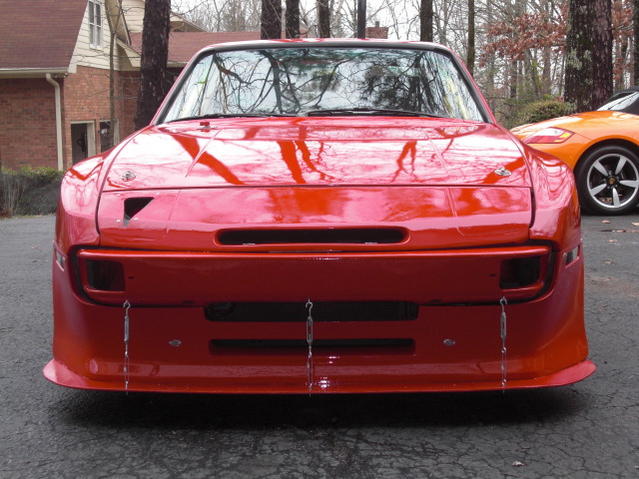
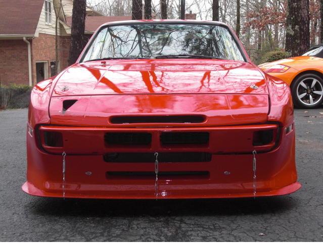
Below is a pick of the front end that I will be using on the car. I may attempt to open the intake area up even more by cutting two openings in the bumper. (photoshop below). The duct in the header is being sealed.
I'm going to move the air intake to the headlight well so that more of the radiator is exposed.
A larger oil cooler may be necessary but I will start with the stock and go from there. It will be ducted separately from the IC/radiator.
Below is a pick of the front end that I will be using on the car. I may attempt to open the intake area up even more by cutting two openings in the bumper. (photoshop below). The duct in the header is being sealed.
08-04-2010, 03:13 PM
#747
Developer
Thread Starter
Carl, it needs to be M10 eye one end and M8 eye the other. 10 to go through the bracket and 8 with the spacers from the alternator turnbuckle, used as reducers and spacers. The minimum of 68 is crucial but maybe 80mm to the max adjustment any more and the alternator starts to go over centre to negative adjustment.
08-04-2010, 04:09 PM
#748
Burning Brakes
Lemming, when designing your ducting and intake holes remember you only need the intake hole to be roughly 1/3 the size of the face of the cooler. No need to go overboard on the size of the hole as it wont improve the cooling as if its too big the air will take the easy option and some of it will flow back out the intake hole.
08-05-2010, 01:54 PM
#749
Rennlist Member
Tim... What an awesome job... That looks terrific... This is exactly what I am trying to do with #75 incorporating the splitter on to a lower running front bumper edge....
car is looking fantastik!
car is looking fantastik!
08-05-2010, 03:52 PM
#750
Nordschleife Master
