When you click on links to various merchants on this site and make a purchase, this can result in this site earning a commission. Affiliate programs and affiliations include, but are not limited to, the eBay Partner Network.
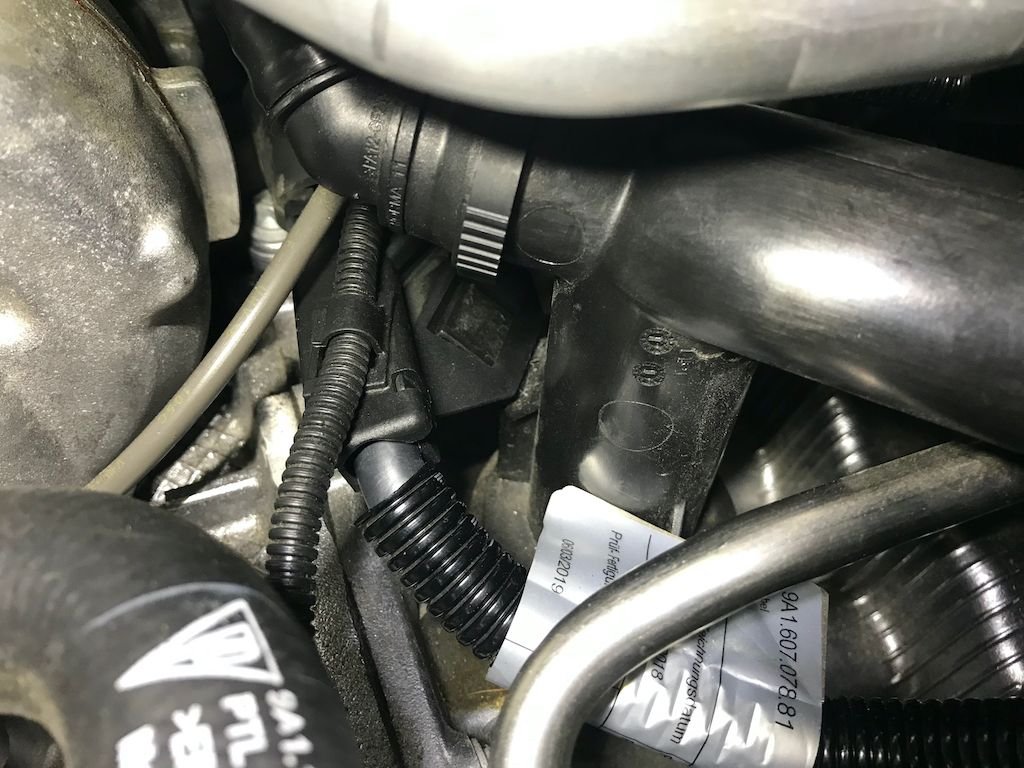
It's impossible to unlatch this cable assembly from the clip on the oil fill pipe (post 2, diagram 1, part 21), as the latch is underneath and only accessible from the end facing the pipe.
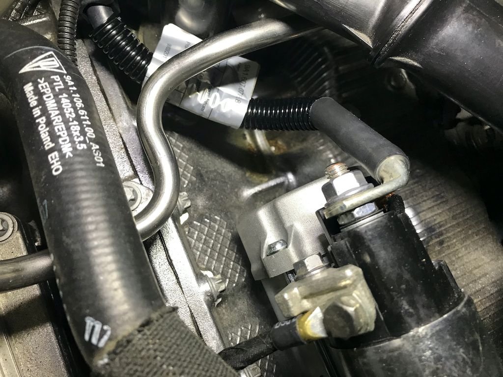
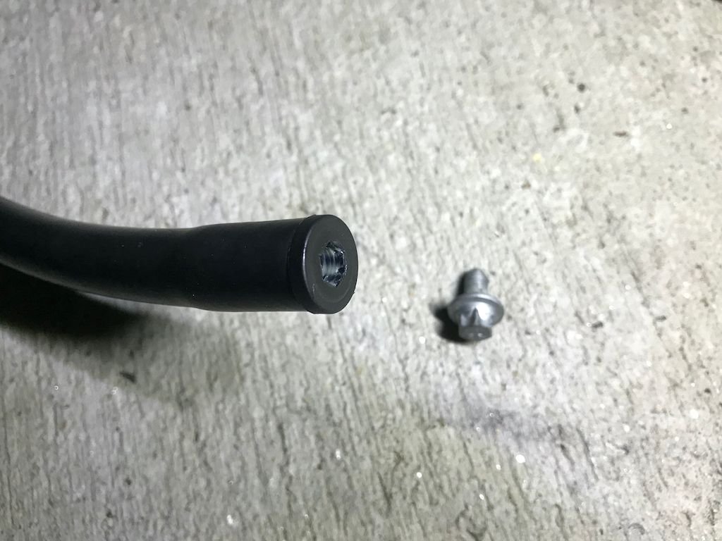
To remove it I had to chisel off the top end of the connector.
When I installed the new one I left it unlatched.
You mean the the starter wire is connected to the oil fill tube?
Do you have pics from your engine without the intake?
This is where the wiring harness latches to the oil filler tube;
Longer starter cable dips down to make room for vacuum unit;
At 370 miles I rerouted the PCV system to vent to atmosphere, and later to catch can.
Intake manifold and runners were dry, so at ~4K miles this oil is from the valve guides;
It's impossible to unlatch this cable assembly from the clip on the oil fill pipe (post 2, diagram 1, part 21), as the latch is underneath and only accessible from the end facing the pipe.
To remove it I had to chisel off the top end of the connector.
When I installed the new one I left it unlatched.
I'm assuming the oil dripping down from your intake runners escaped from the less than perfect AOS.
I used a flat head screwdriver and hammer to crack the connector.
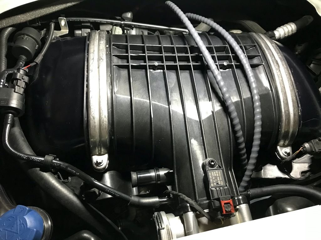
The Clubsport intake gives the car a nice linear power band, noticeable starting between 4 and 5K RPM, with a meatier top end.
A worthy upgrade.
The bigger intake requires a specific installation procedure, positions relative to front of car;
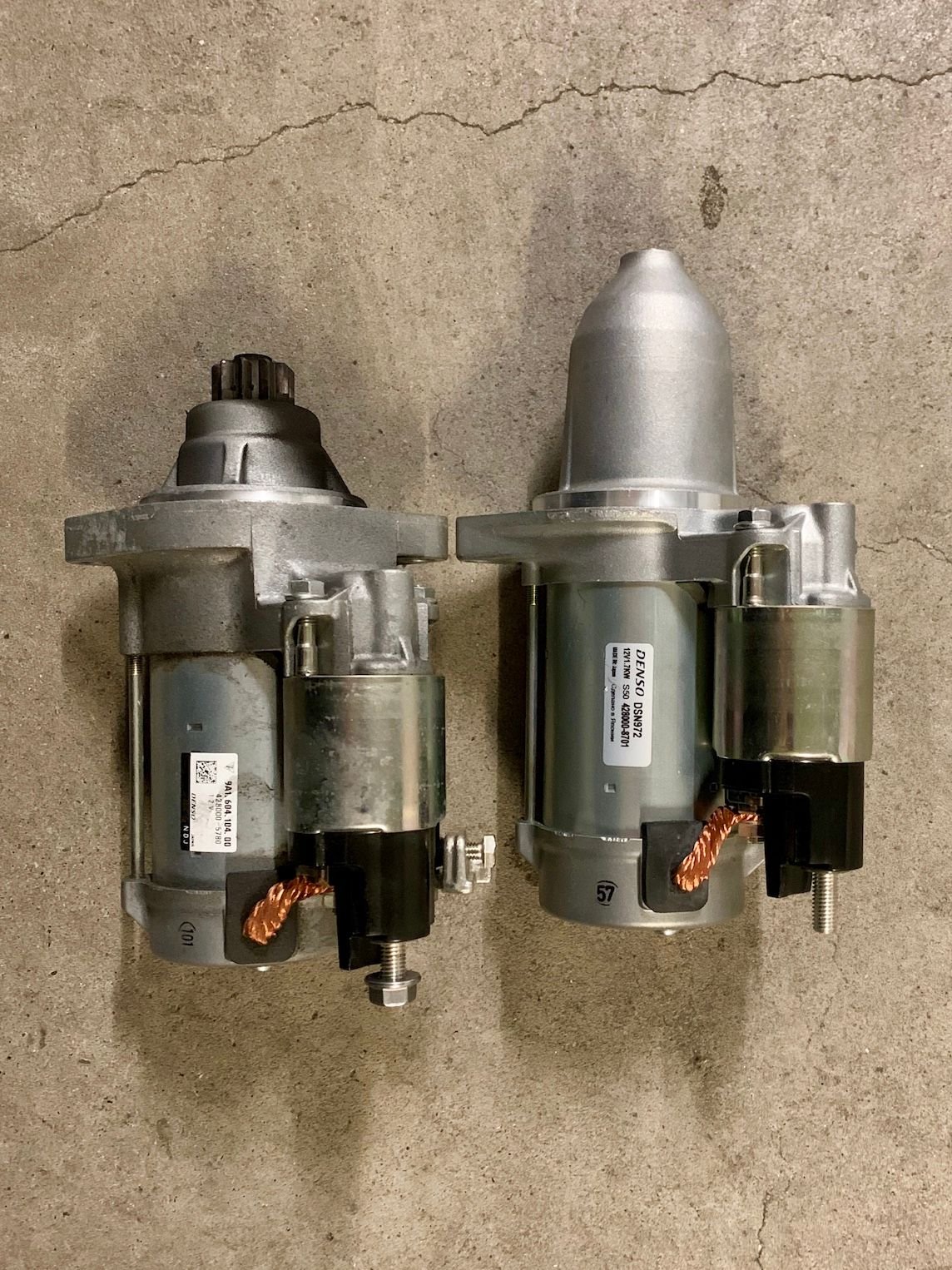
01. Shorter starter
02. Longer wiring harness
03. Unscrew right front AC metal bracket, won't fit, leave plastic and rubber assembly
04. Intake runners
05. Slide temperature sensor into right intake runner half moon opening if you have one, else tie wrap to intake runner boss hole
06. Rubber gaskets onto runners out of the way of space between
07. Rubber intake boot, don't tighten band clamps
08. Attach longer 3.5mm ID vacuum line to connector underneath manifold
09. Fit manifold between runners, push forward
10. Bolt throttle body onto manifold, pull assembly back into boot
11. Slide gaskets over manifold and runner gaps
12. Fit metal half clamp pairs over gaskets, with spacer bolts to front, tighten
13. Tighten boot band clamps
14. Plug connecter into throttle body
15. Bolt down left front metal bracket to runner
16. Don't bolt left rear metal bracket to runner, won't fit
17. Bolt down right rear metal bracket and right side of plastic wiring harness to runner
18. Tie wrap left side of plastic wiring harness to manifold's FOS intake line
19. Plug FOS intake with 15/16" OD tapered rubber plug if using catch can, otherwise connect new FOS hose
20. Because of 17, now able to plug connector into manifold sensor
21. Cut off right angle connector from vacuum line, attach line to left side manifold connector with 5/16" ID PCV hose
22. Cut one inch square from the cover pad above the manifold sensor, otherwise the pressure causes intermittent throttle and downshift blip loss.
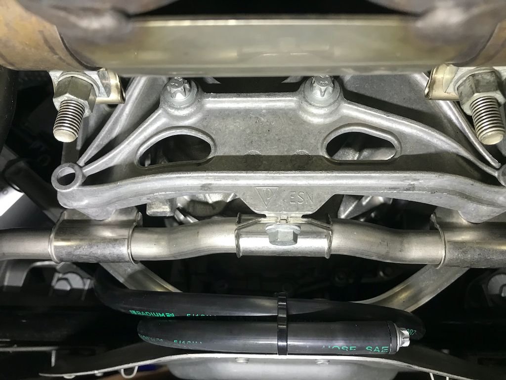
Attached 6' of 5/16" ID PCV hose to right side manifold connecter, threaded hose down through left side spiral brake line section.
Fitted the plastic hollow shaft from step 03, blocked off with bolt.
Looped hose around bracket, secured with removable tie wrap.
This will be the port for drip atomizing Redline SI-1 into the intake every 1K miles to clean the carbon and oil deposits from the valves and surrounding area;
Installed the Advanced Flow Engineering Pro Dry S air filters as well;
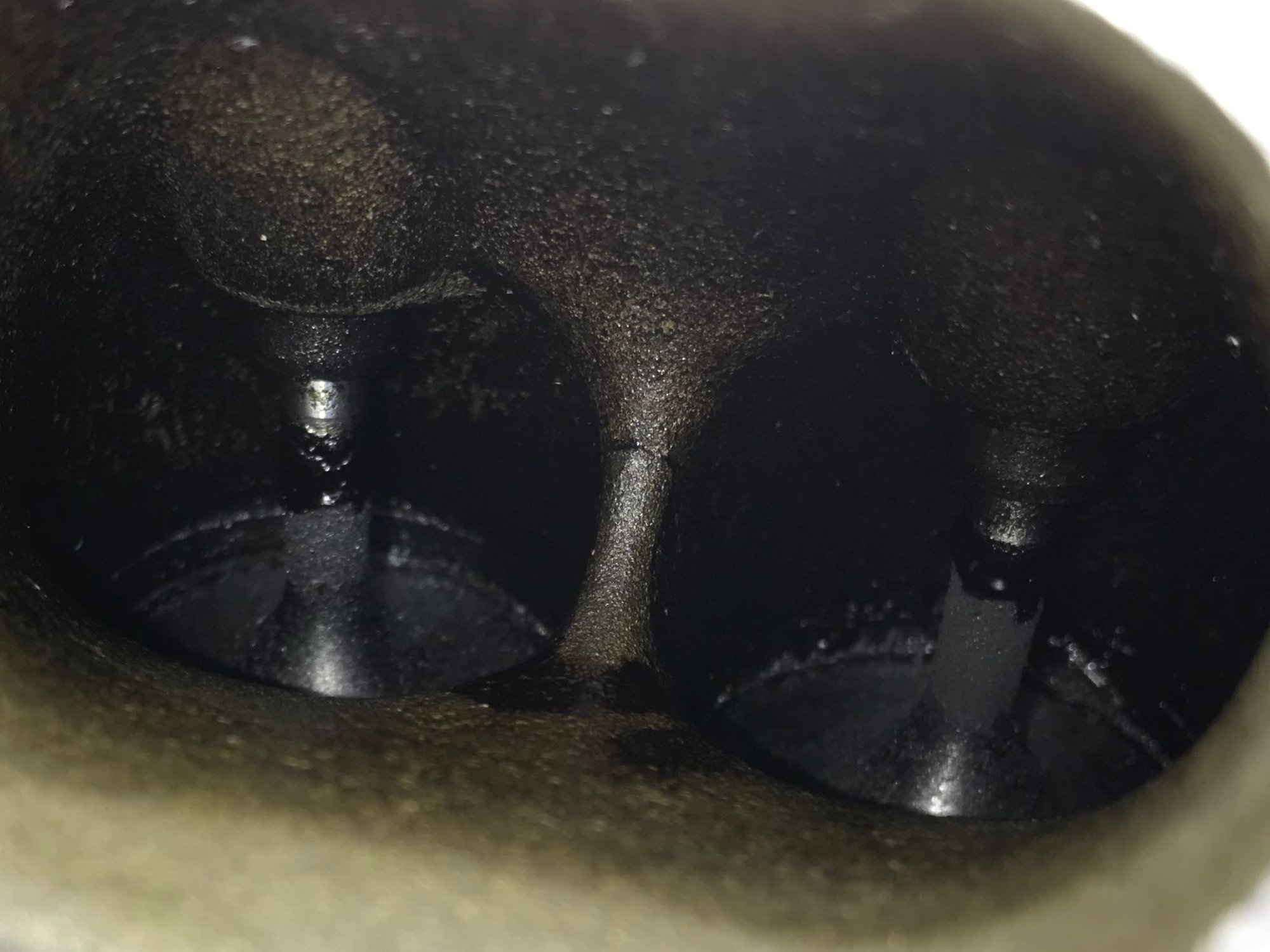
The starter gear pops up into place when engaged.
Looks like the shroud is for other configurations where the gear's shaft extends and is retained at the top.

 03-23-2020, 09:10 AM


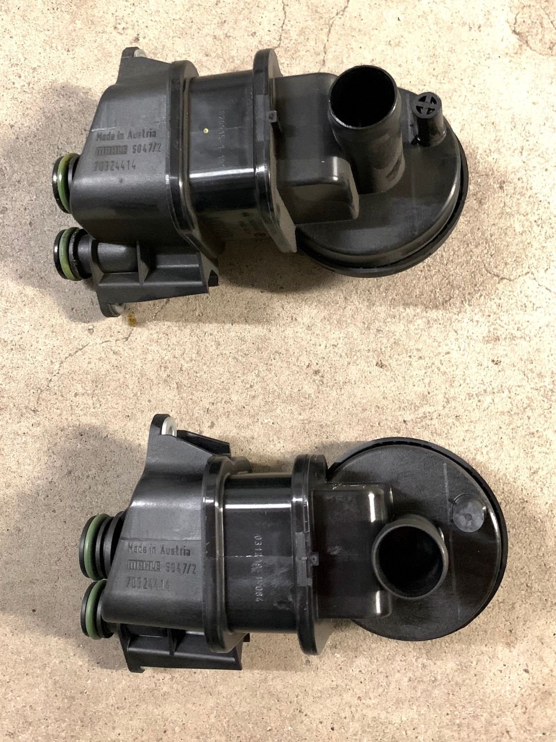
") ) and the latest AOS.
) and the latest AOS.