
Intake madness. Teardown begins....
 02-08-2020, 10:26 PM
#301
Race Car
Thread Starter
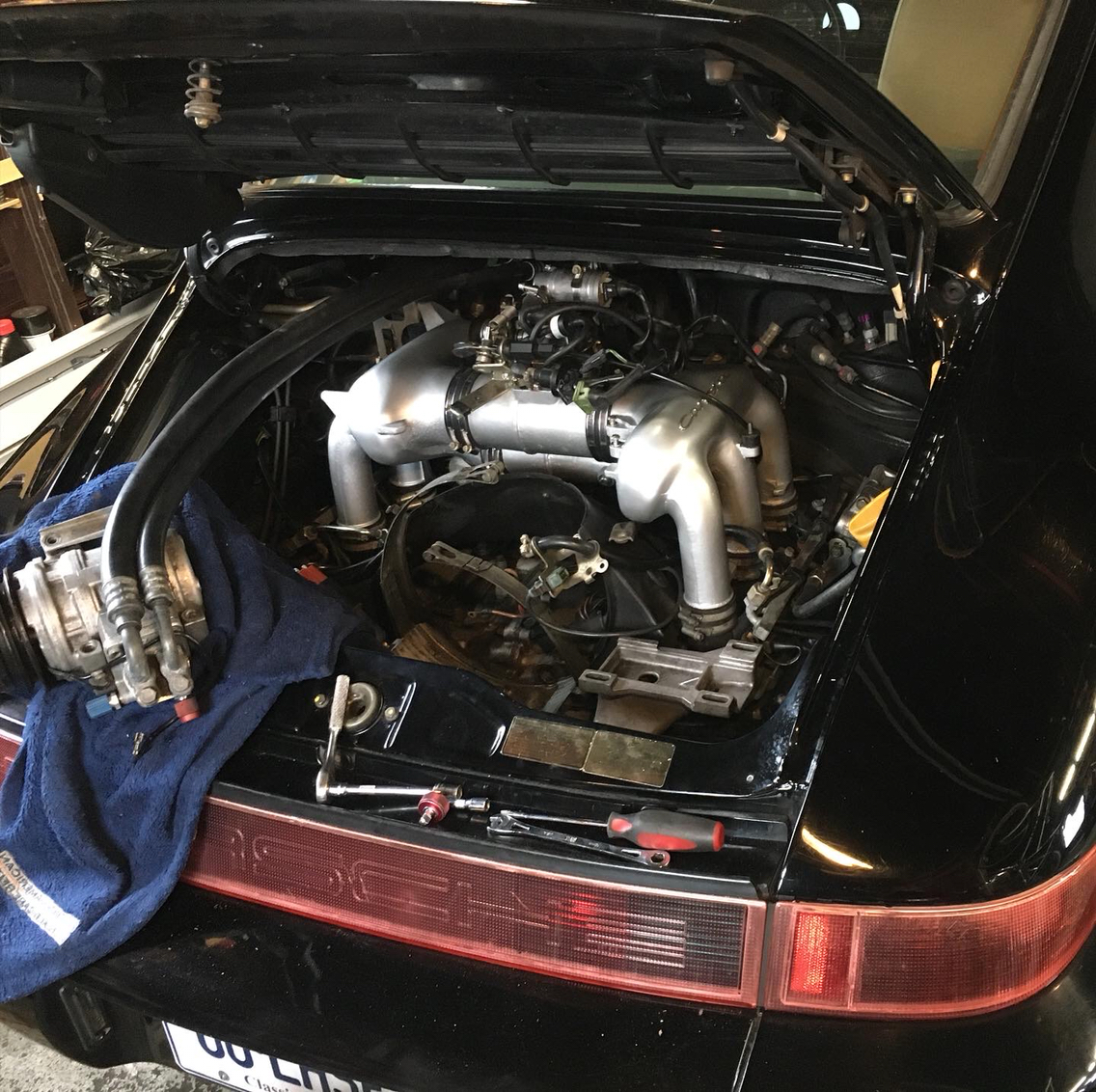
Intake is going to take a back seat for a moment. It's a bit cold this weekend.
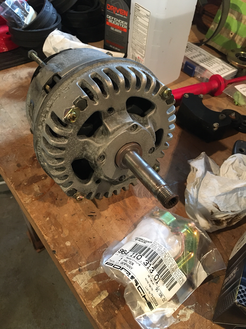
But....i got a couple packages in the mail. One was the fpr bracket from Sunset. This was a special order from Porsche AG, and they asked if i wanted to expedite and it came in days rather than a month, which was what i had expected. Really happy with those guys. So maybe that will have to get installed tomorrow- or we will have an attempted install...let's see.
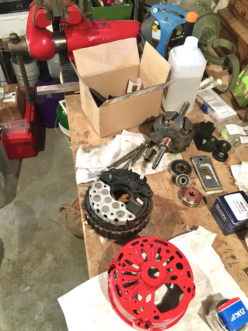
The other box however- the other box was exciting....something that can be done in a heated basement shop...alternator rebuild parts.
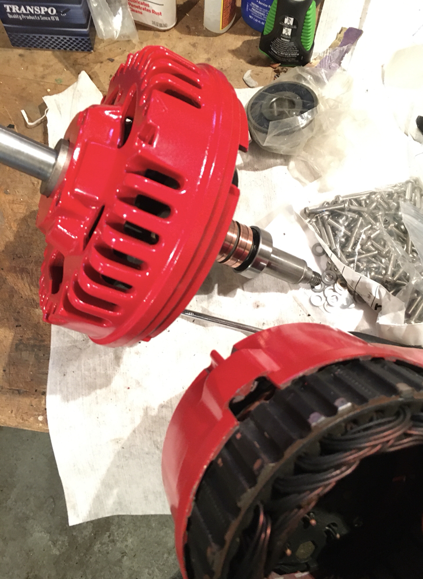
Well, it was exciting until i realized. But before going there, let's just tear down the alternator. There is a great DIY on the penguin site called something like Porsche 964 alternator rebuild. Which is so very imaginative...nothing mad about it at all. Very straight forward.
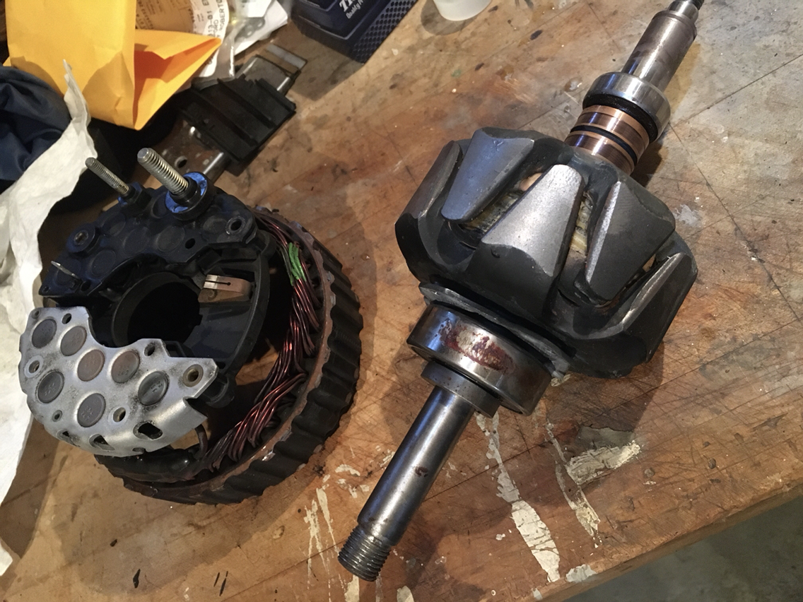
So we start to unscrew things...
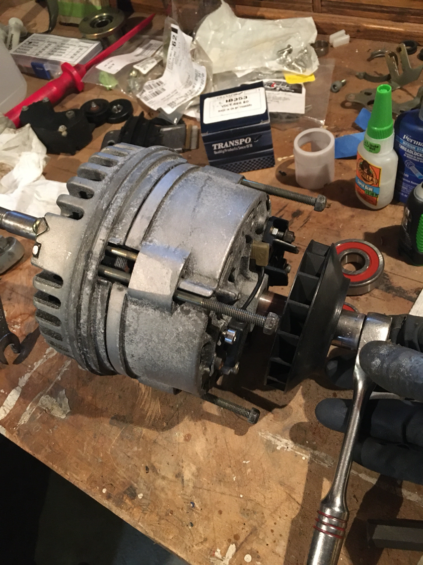
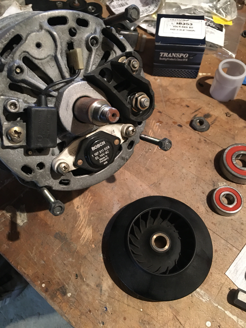
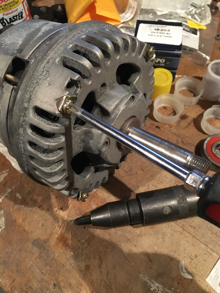
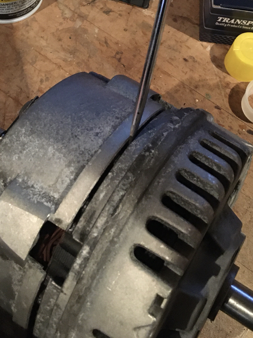
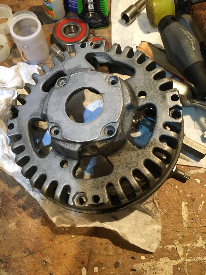
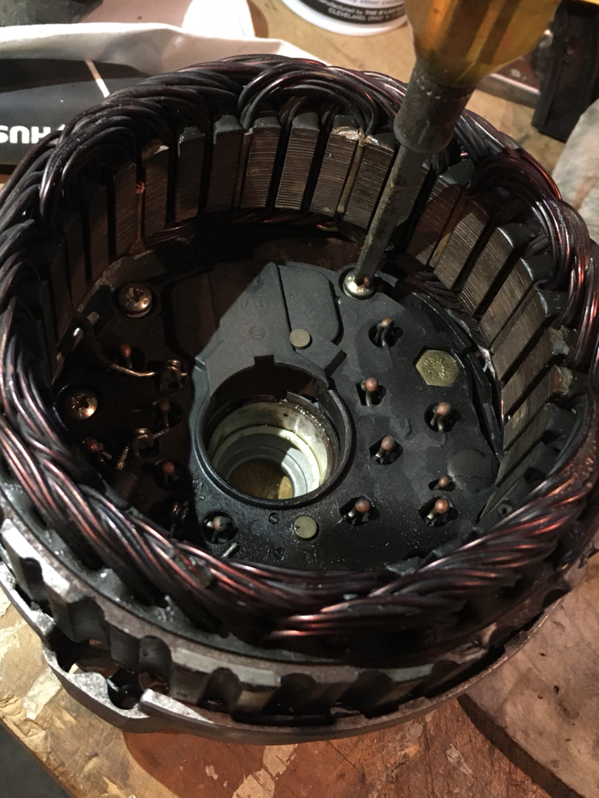
So that's it. I'm not going to explain that process. The other diy does a good job, and honestly you kinda don't even need it. Just unscrew things and split the halves and bang the armature out (carefully). You aren't going to reuse the bearings, so you don't have to be all that delicate. Just don't hurt the electrical parts.
Word to the wise- the screws are going to be sticky. But I'll get to the replacement screw sizes in the next post...
But....i got a couple packages in the mail. One was the fpr bracket from Sunset. This was a special order from Porsche AG, and they asked if i wanted to expedite and it came in days rather than a month, which was what i had expected. Really happy with those guys. So maybe that will have to get installed tomorrow- or we will have an attempted install...let's see.
The other box however- the other box was exciting....something that can be done in a heated basement shop...alternator rebuild parts.
Well, it was exciting until i realized. But before going there, let's just tear down the alternator. There is a great DIY on the penguin site called something like Porsche 964 alternator rebuild. Which is so very imaginative...nothing mad about it at all. Very straight forward.
So we start to unscrew things...
So that's it. I'm not going to explain that process. The other diy does a good job, and honestly you kinda don't even need it. Just unscrew things and split the halves and bang the armature out (carefully). You aren't going to reuse the bearings, so you don't have to be all that delicate. Just don't hurt the electrical parts.
Word to the wise- the screws are going to be sticky. But I'll get to the replacement screw sizes in the next post...
 02-08-2020, 10:32 PM
#302
Race Car
Thread Starter
Did i mention i wasn't alone through that teardown? I had a visitor...
But then after he took off, i thought to get back to the teardown and get my new bearings in...
But noooooooooo
I'll explain.
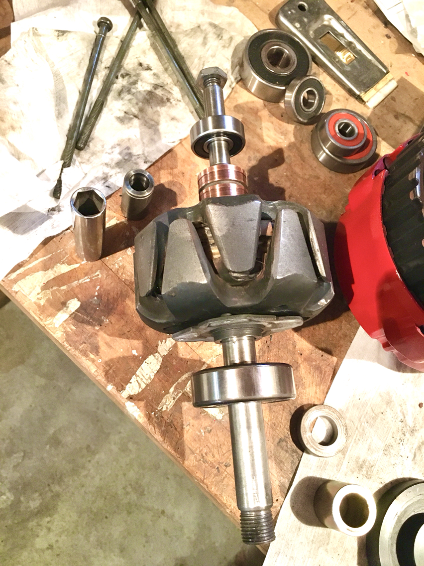
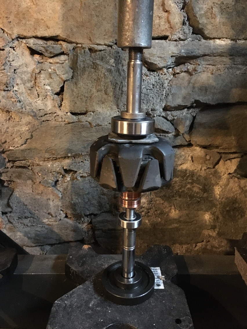
First, we break out the best/worst tool ever...which you really could say about any Pittsburg tool- but when it comes to bearing pullers- these are crap- but crap will usually do the job.
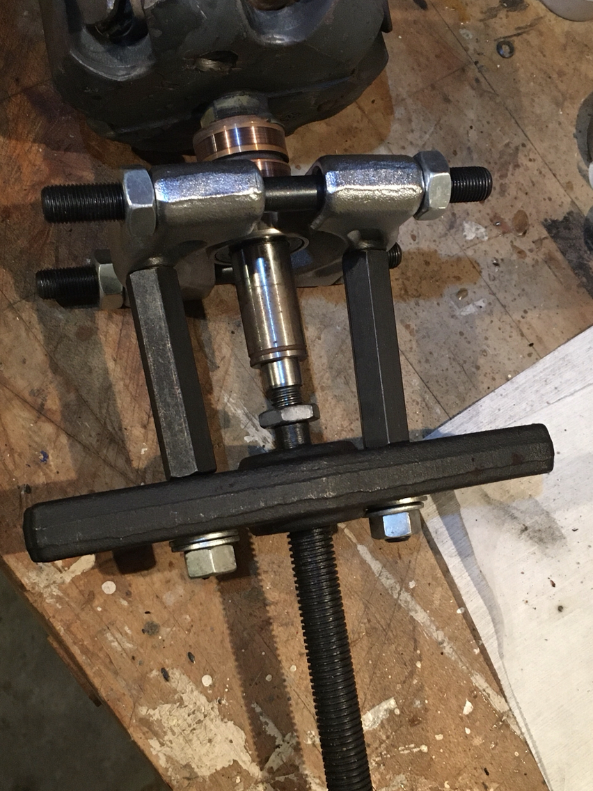
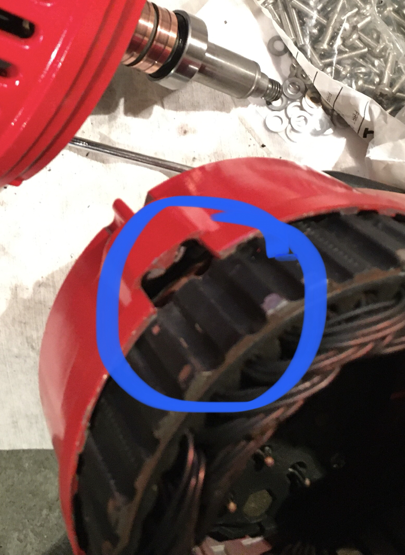
They came right off. But here i the thing.
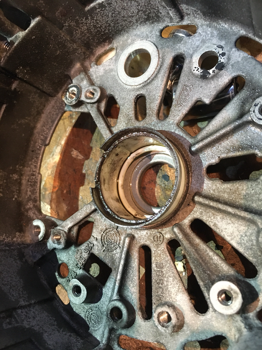
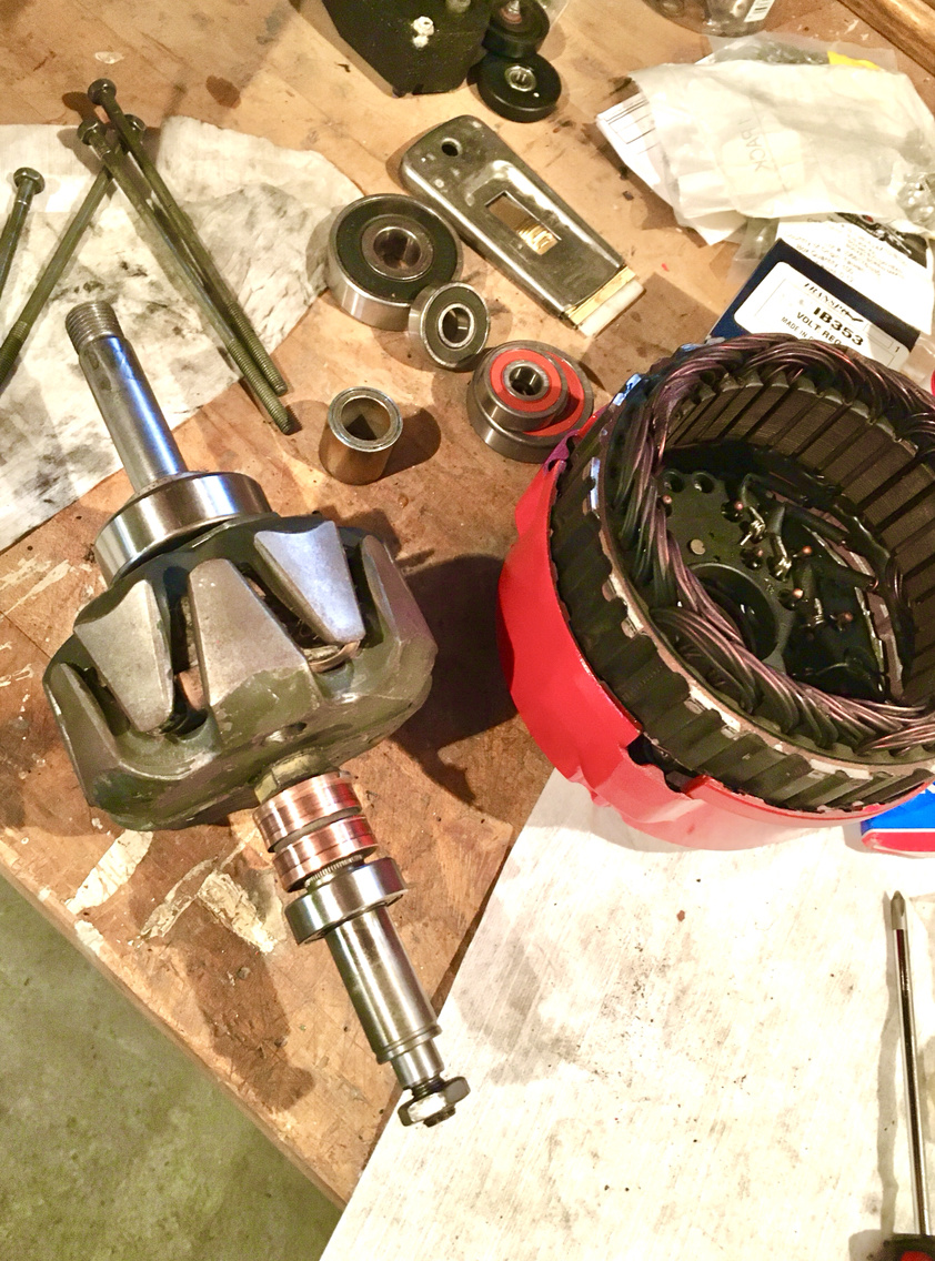
Maybe the info was right for that other guy on that other thread- but for my alternator, his larger bearing size was incorrect. That said, when i ordered my rebuild kit, it came with the bearings for his alternator. So i had to put it all down and make a bearing order.
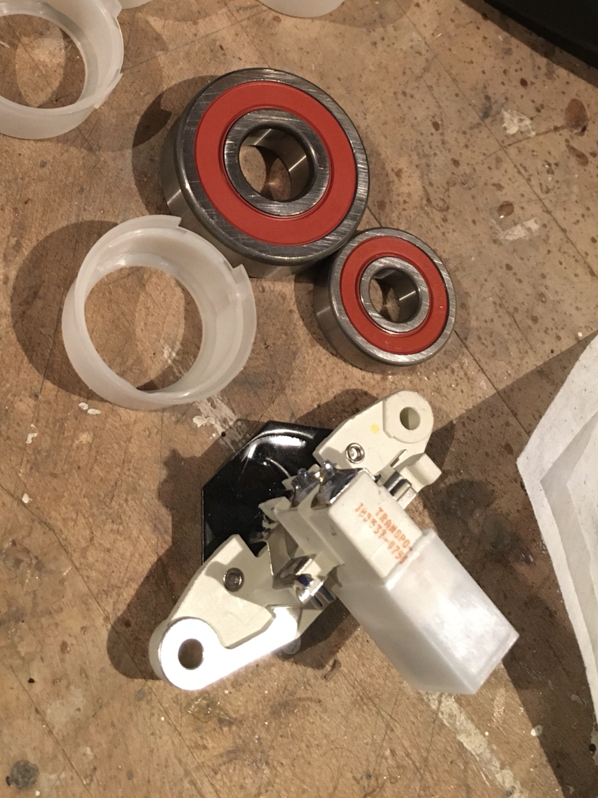
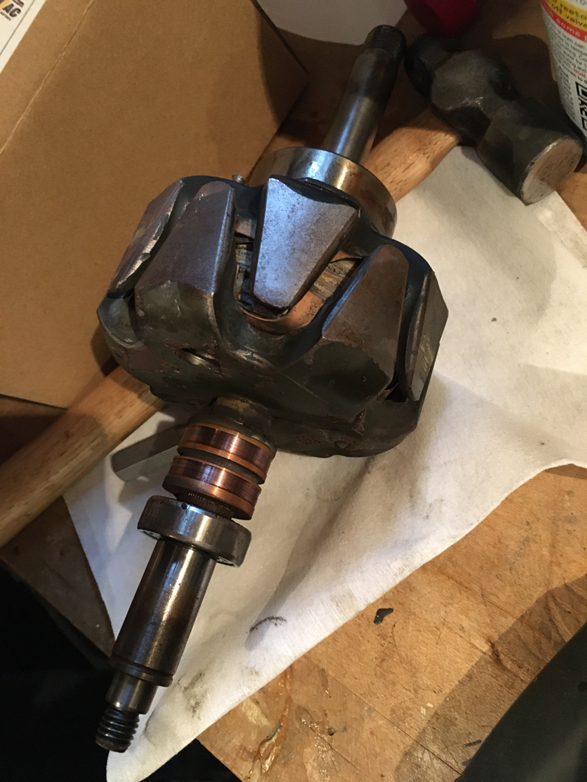
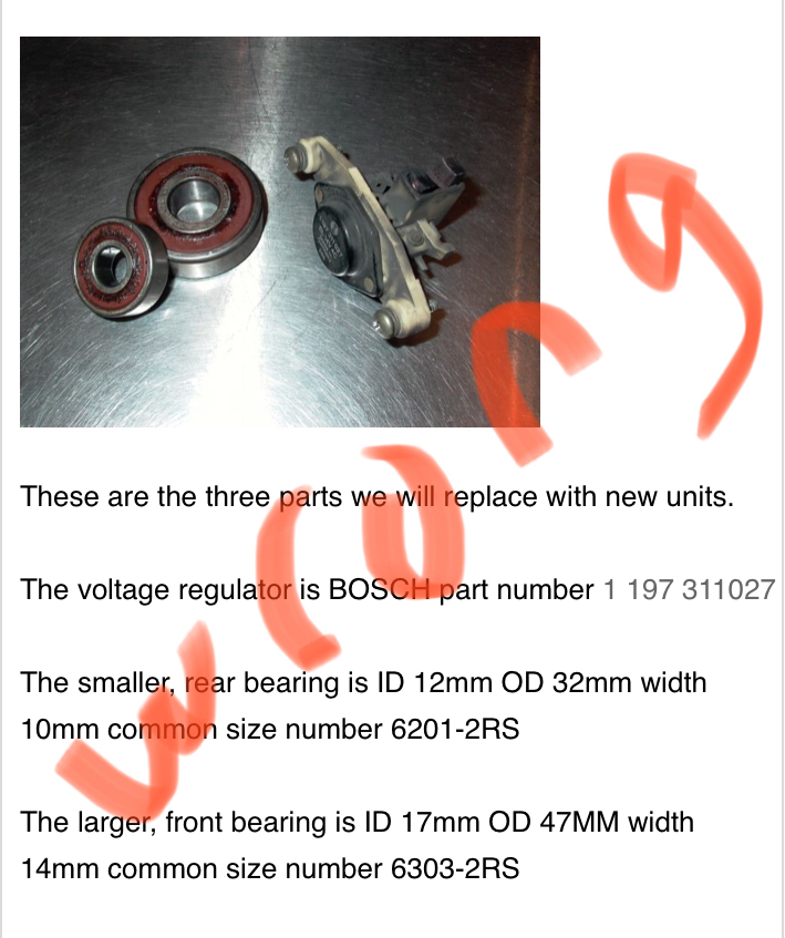
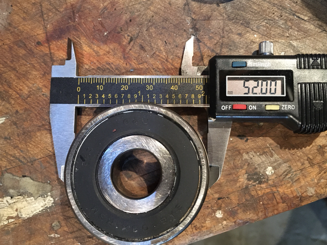
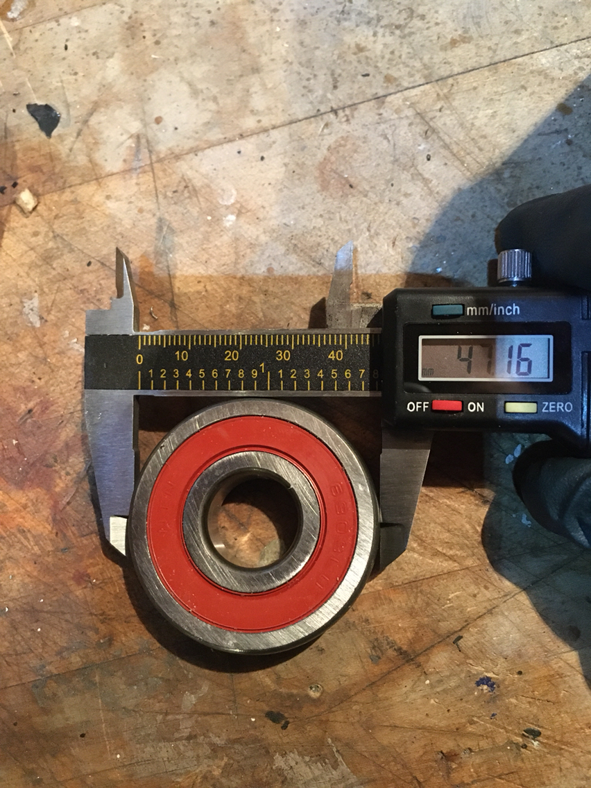
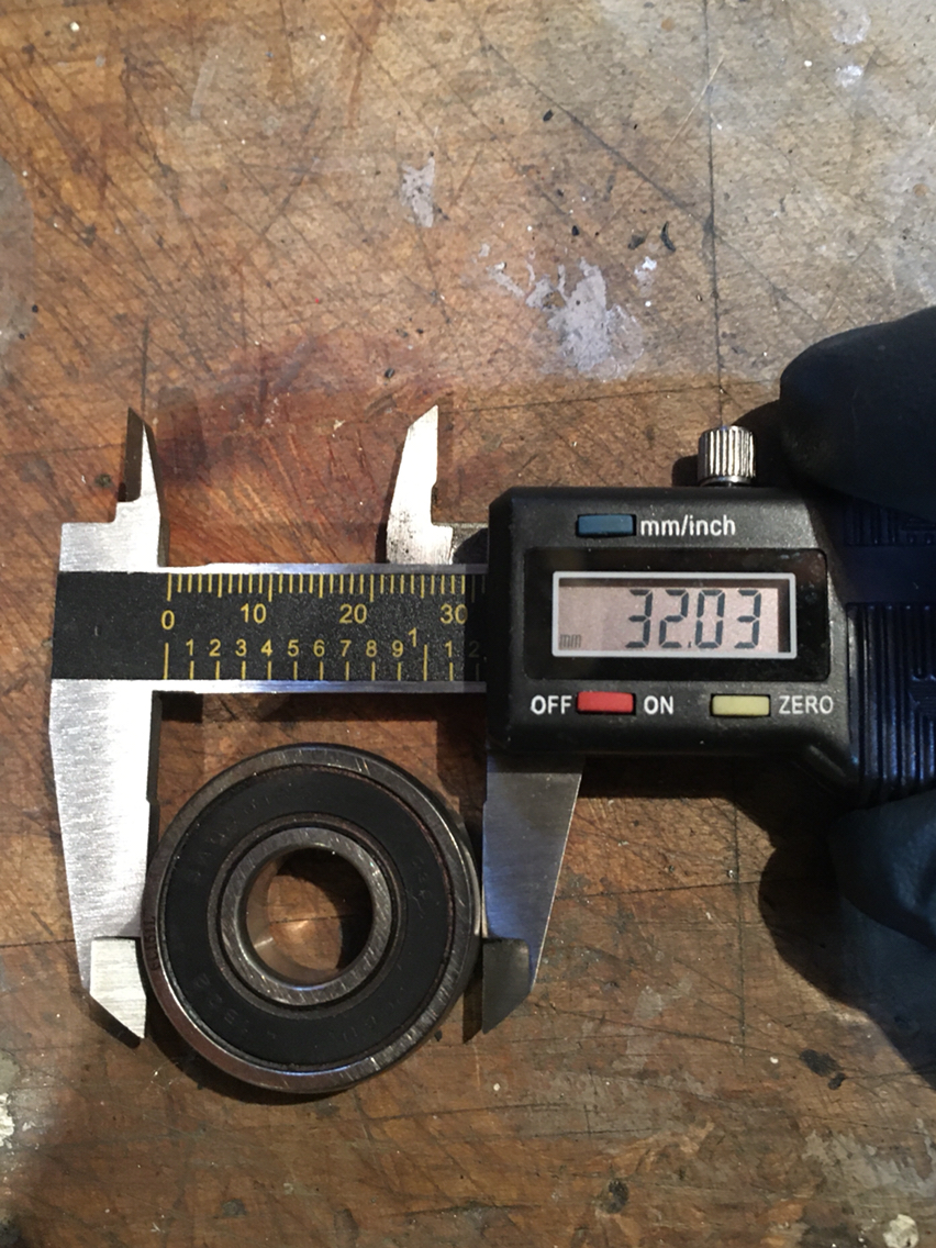
Here is the correct larger bearing for my alternator- the one that i pulled out:
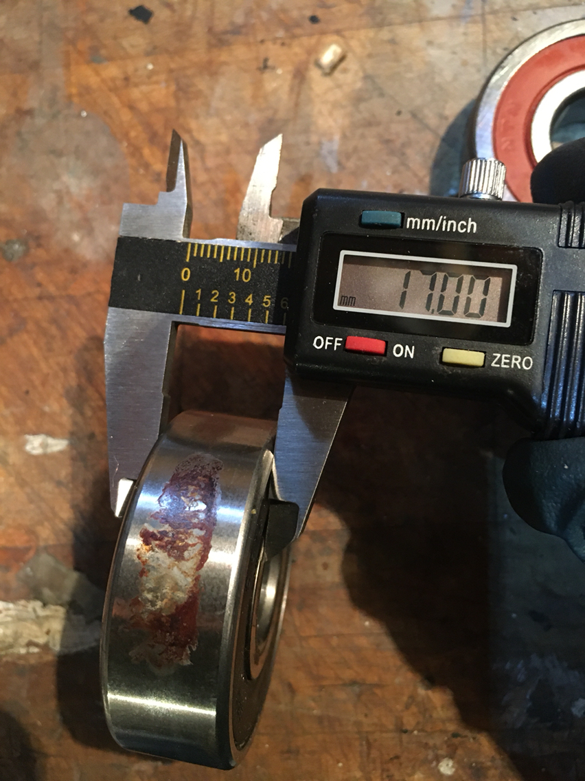
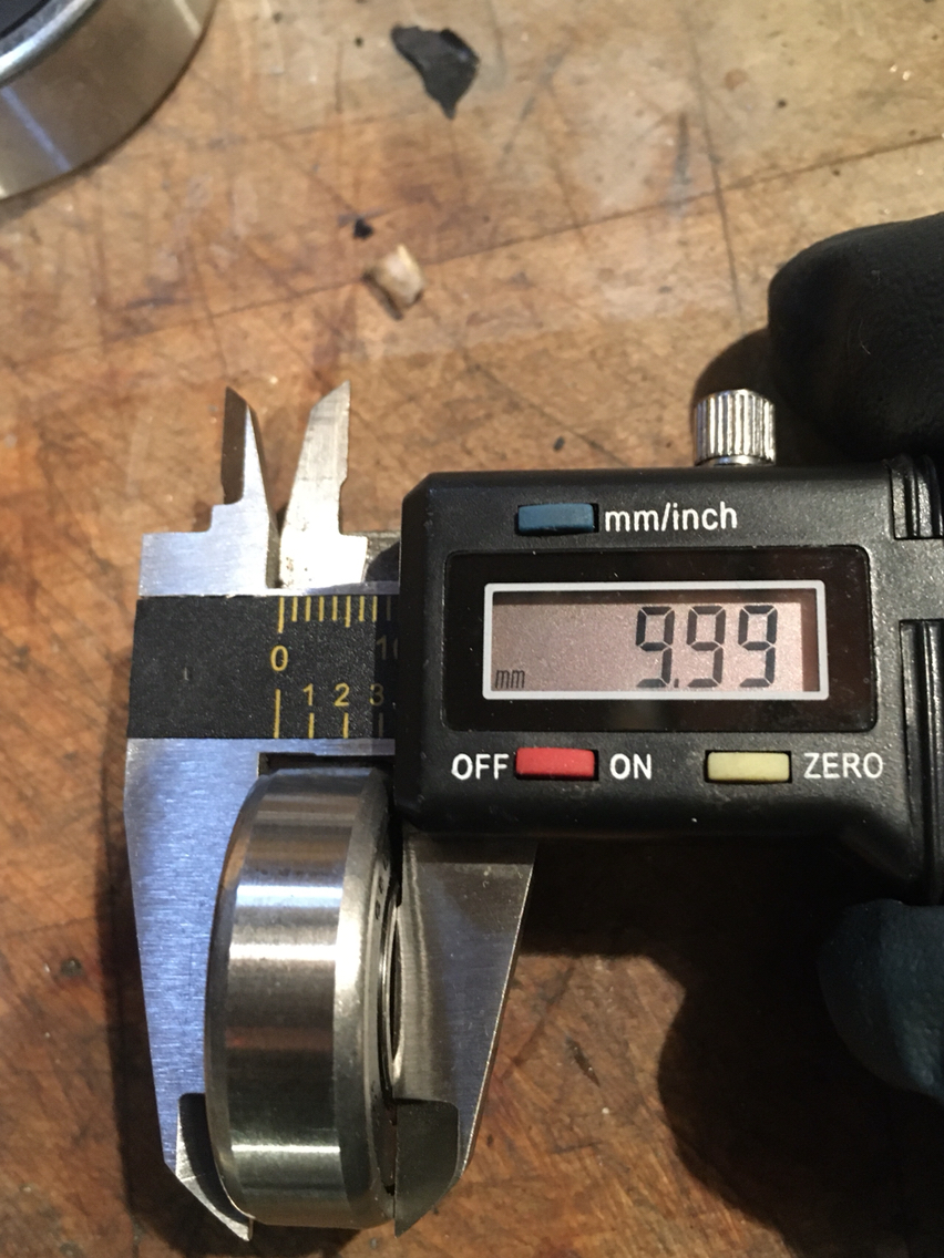
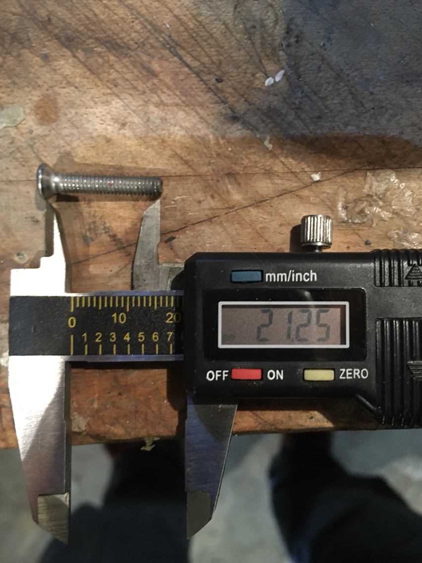
This was the incorrect size that came new today:
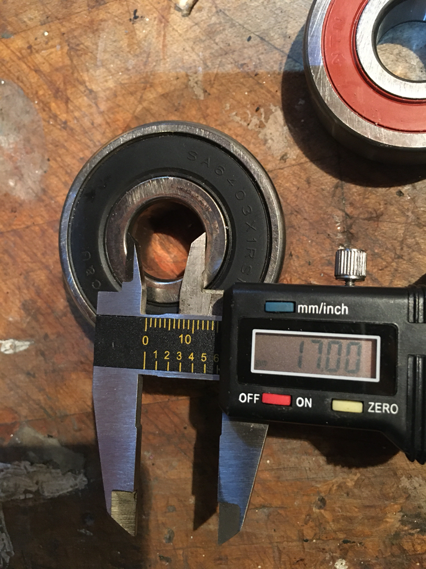
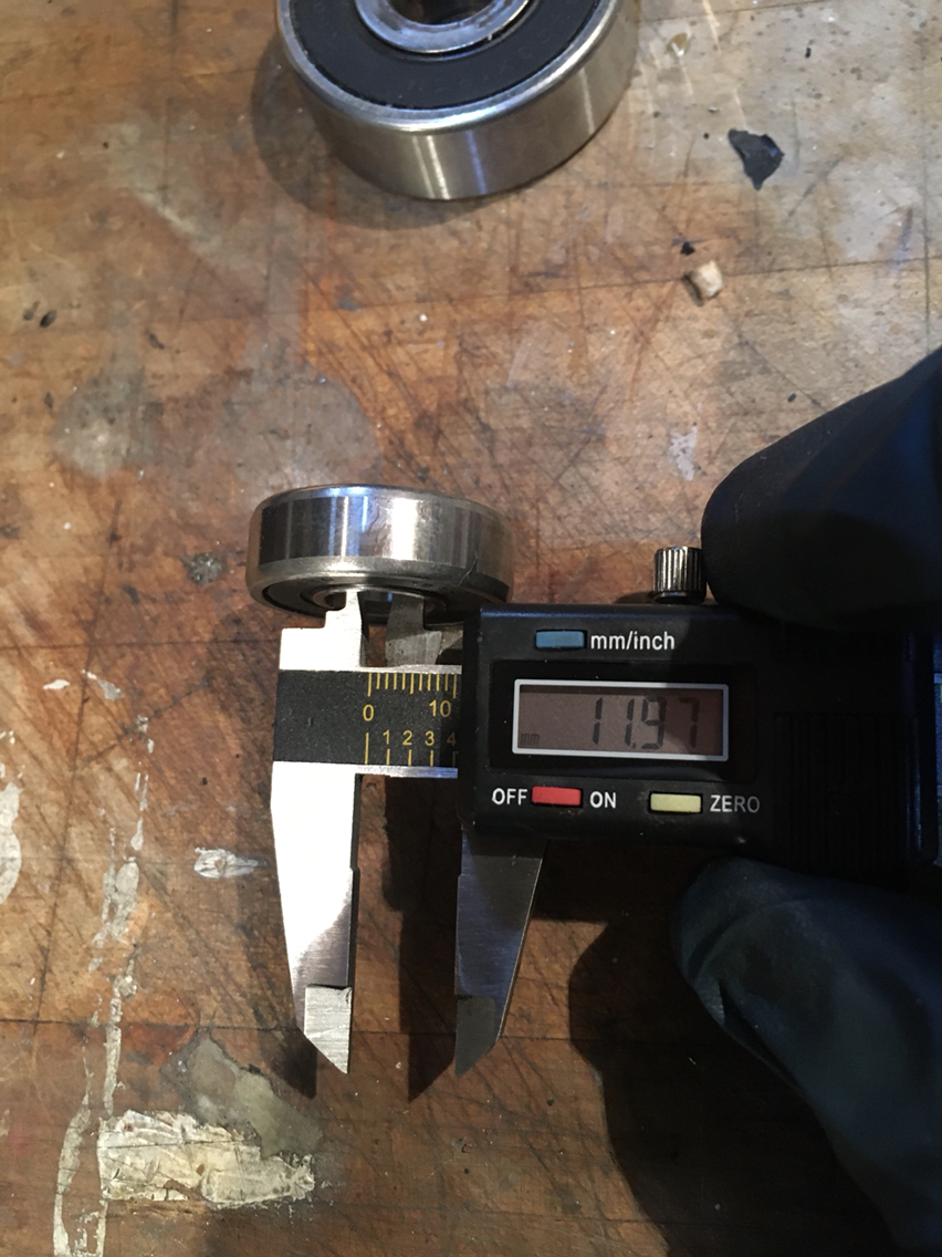
And here is the smaller rear bearing that came out of my alternator:
And if you, like me, have sticky philips and they cam out and strip the heads- here are some basic measurements for replacement:
M5:
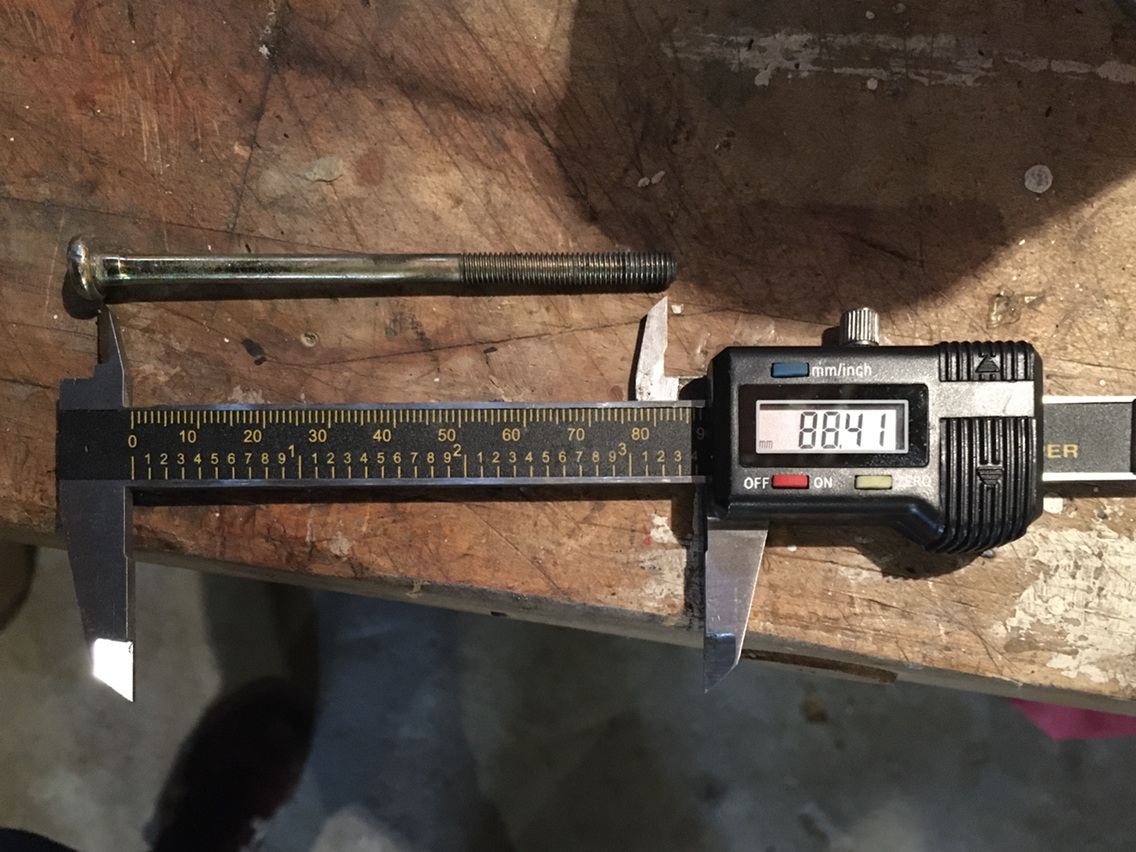
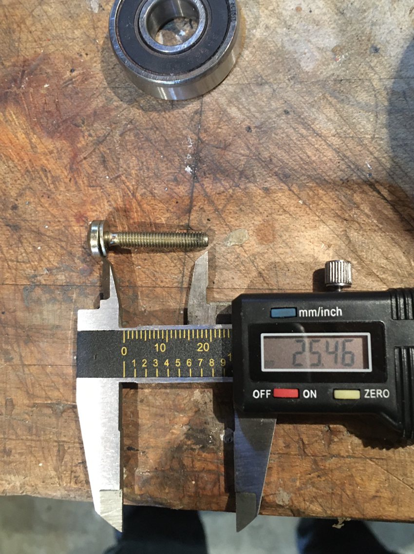
M4:
So- my order was placed tonight for bearing and also for screws from McMaster. More to come. If i can get the time and get the garage heated a bit tomorrow I'll get back to the intake and stripping the fan housing.
But then after he took off, i thought to get back to the teardown and get my new bearings in...
But noooooooooo
I'll explain.
First, we break out the best/worst tool ever...which you really could say about any Pittsburg tool- but when it comes to bearing pullers- these are crap- but crap will usually do the job.
They came right off. But here i the thing.
Maybe the info was right for that other guy on that other thread- but for my alternator, his larger bearing size was incorrect. That said, when i ordered my rebuild kit, it came with the bearings for his alternator. So i had to put it all down and make a bearing order.
Here is the correct larger bearing for my alternator- the one that i pulled out:
This was the incorrect size that came new today:
And here is the smaller rear bearing that came out of my alternator:
And if you, like me, have sticky philips and they cam out and strip the heads- here are some basic measurements for replacement:
M5:
M4:
So- my order was placed tonight for bearing and also for screws from McMaster. More to come. If i can get the time and get the garage heated a bit tomorrow I'll get back to the intake and stripping the fan housing.
02-08-2020, 11:36 PM
#303
Rennlist Member
Glad I didn't stick around for the "bearing measurement fail" lol. Darn kits...
Actually it was cool taking one of these apart. Good learning experience for when mine fails.
Actually it was cool taking one of these apart. Good learning experience for when mine fails.
Last edited by Meatball964; 02-09-2020 at 09:25 PM.
02-09-2020, 08:41 PM
#304
Race Car
Thread Starter
Today we got back to it... the fan housing is soaking in paint stripper. I'm shocked at how resistant that powder coat is. I'm also shocked at how thick it is.
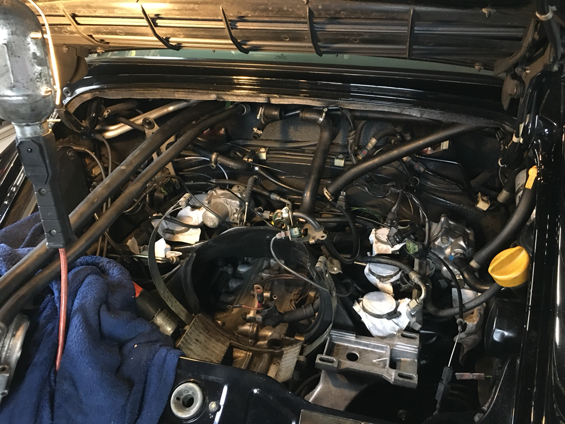
But more on that later . My new fuel pressure regulator bracket arrived, so it was time to get some real work done "backdating" the intake system. I really wish it hadn't been years since the beginning of this project, but life and babies can really get in the way of fun- as can many other 964 and all their woes in the meantime. That said, there are a whole bunch of things that were top of mind when i began, and that have now either disappeared or surprise me when they come back to light.
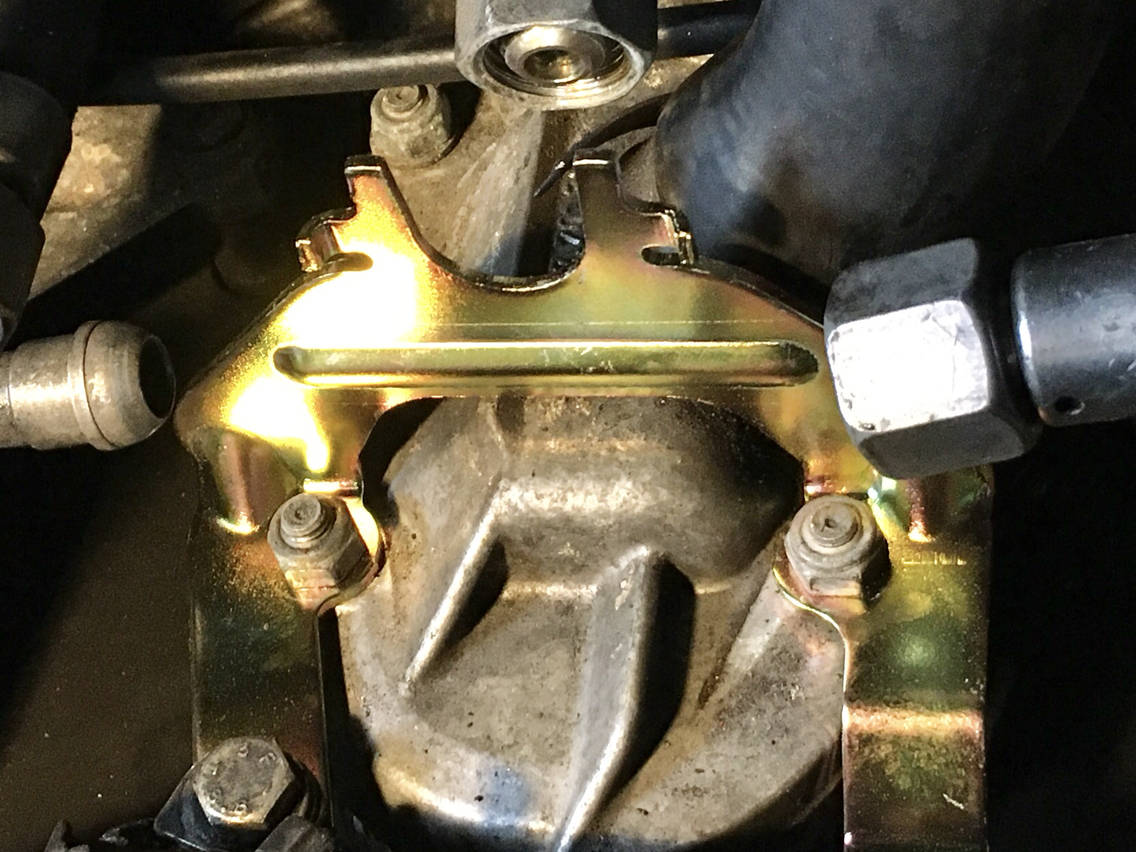
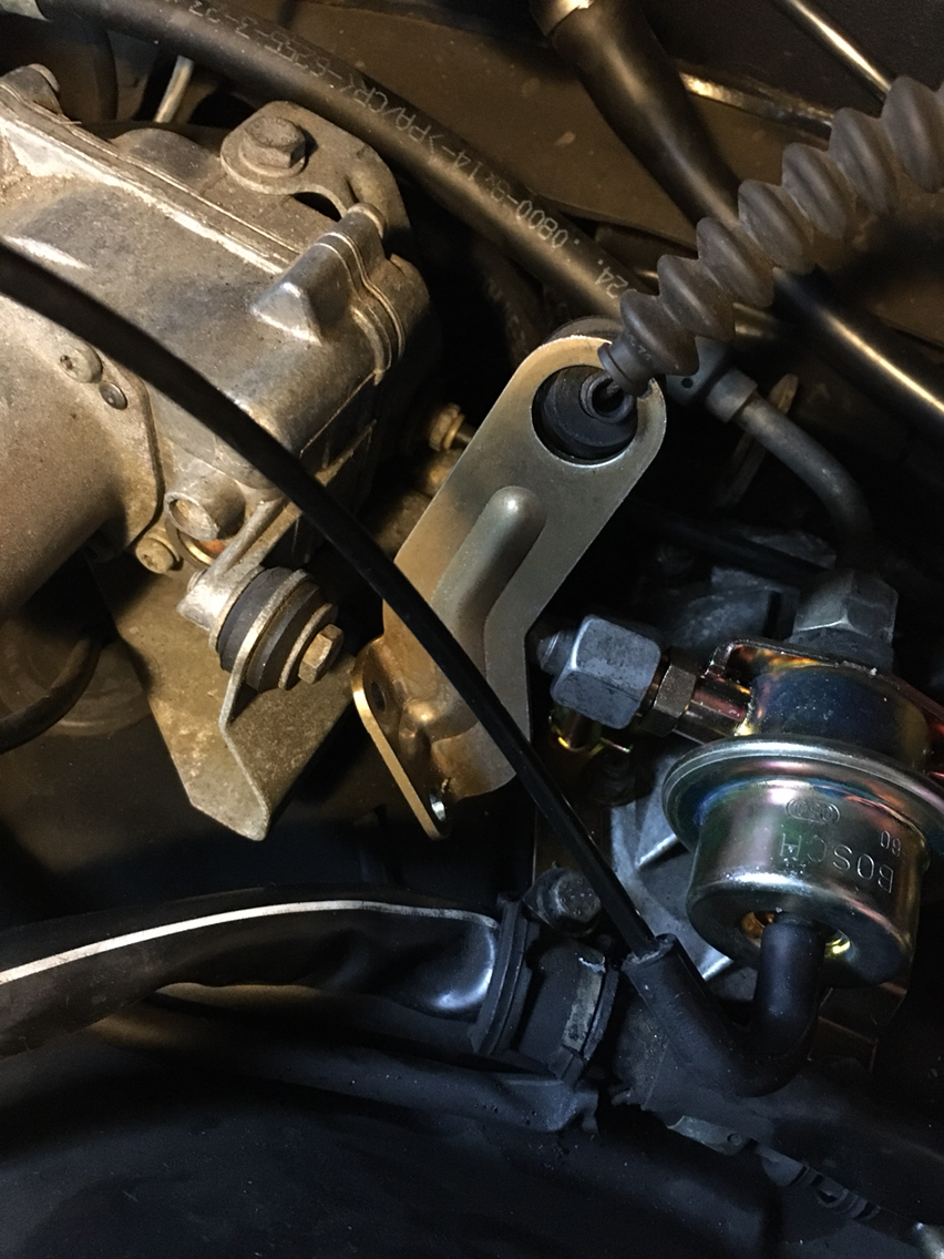
First up, here is the bracket
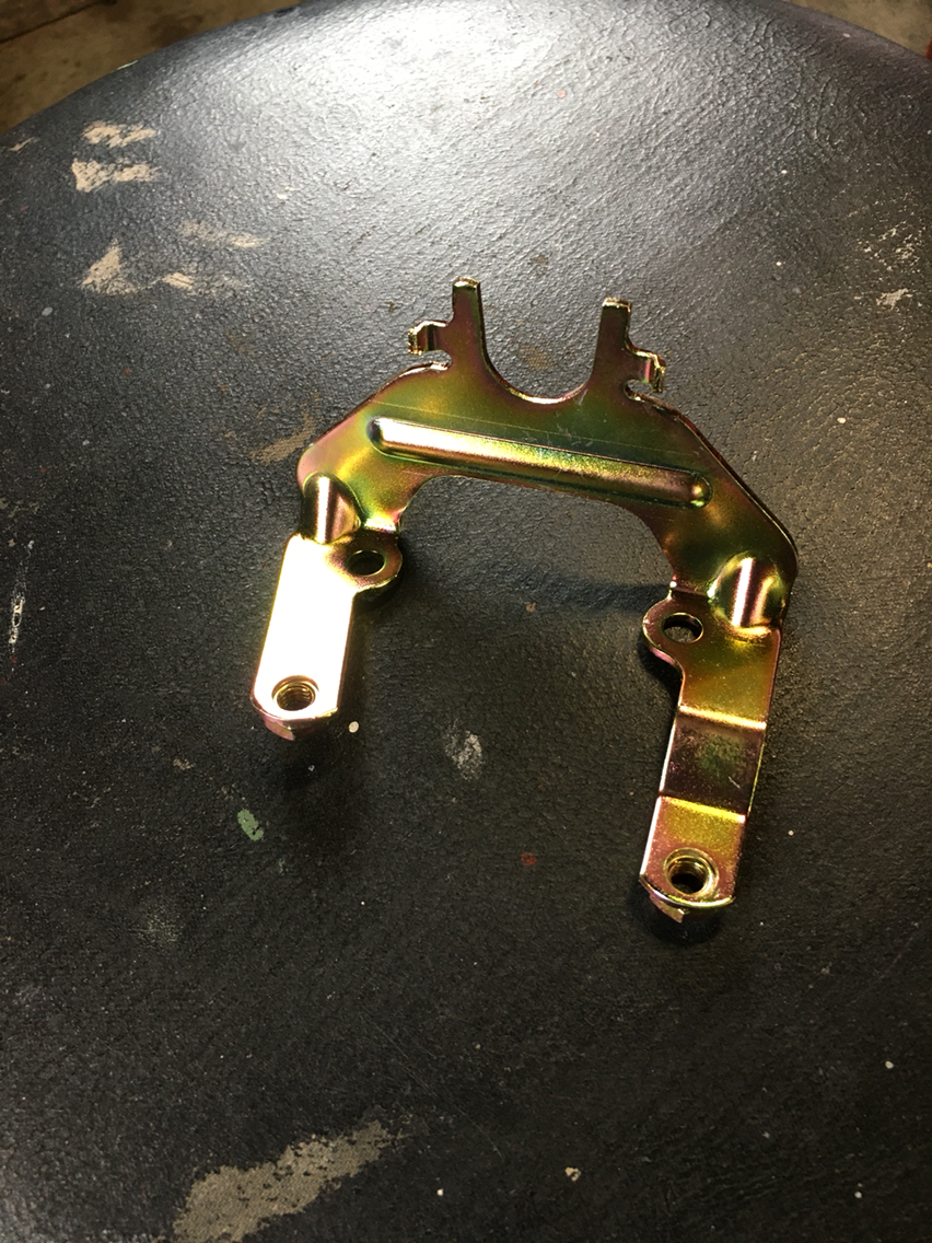
And then when we look at the later setup, there is a bracket down there under the fpr that has mounts for the wiring harness and a fuel line
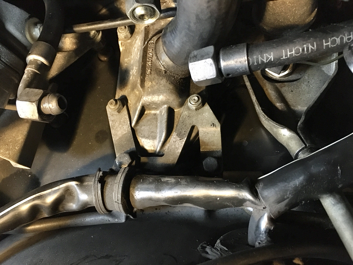
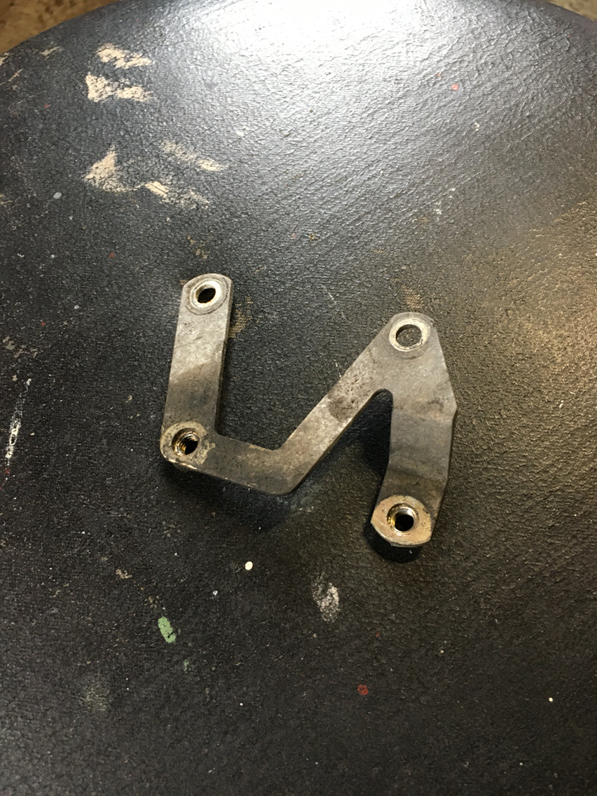
Here it is out...
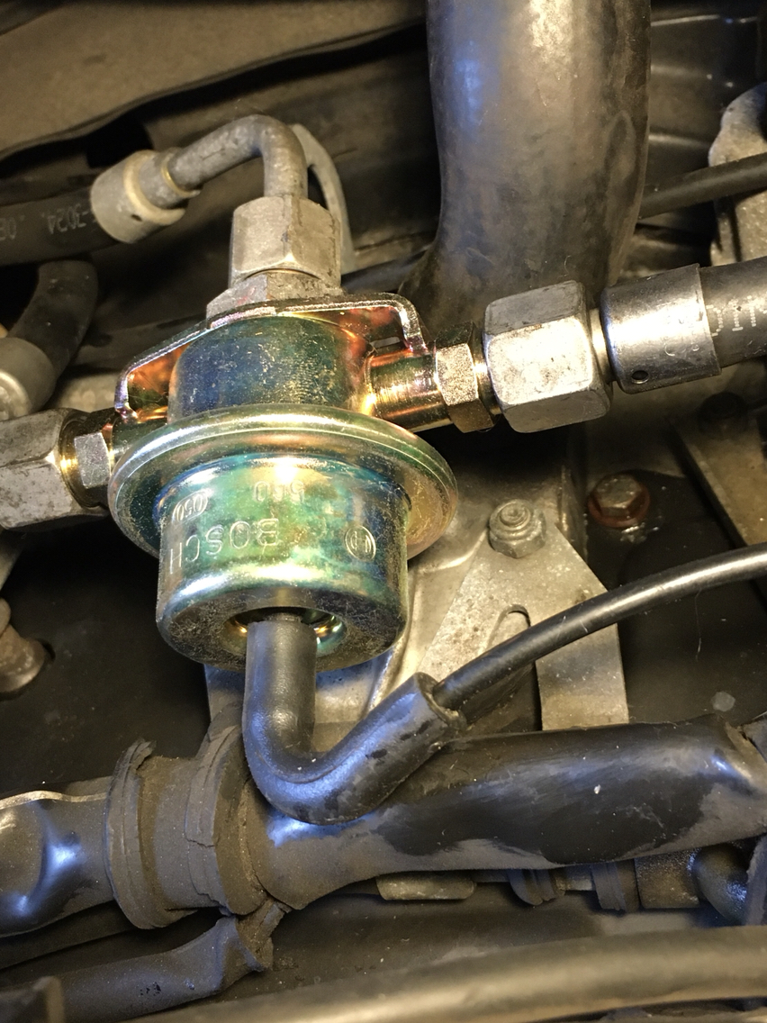
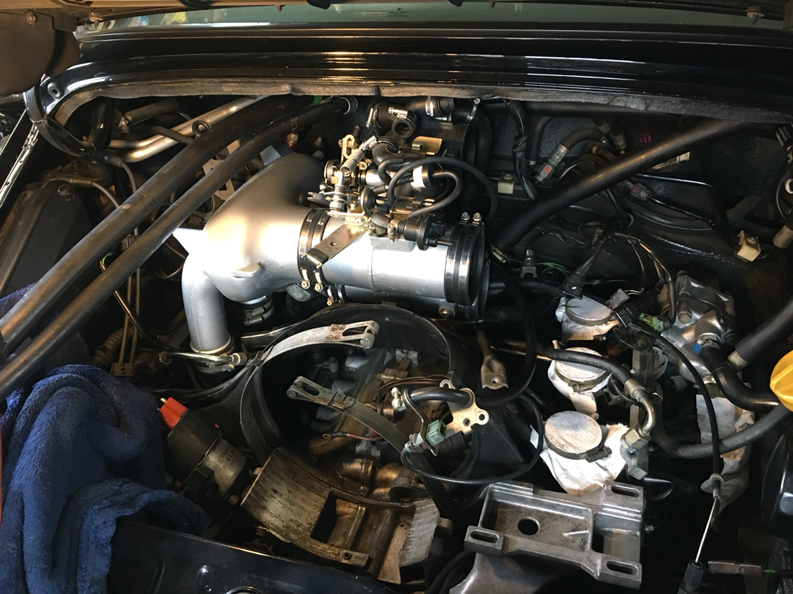
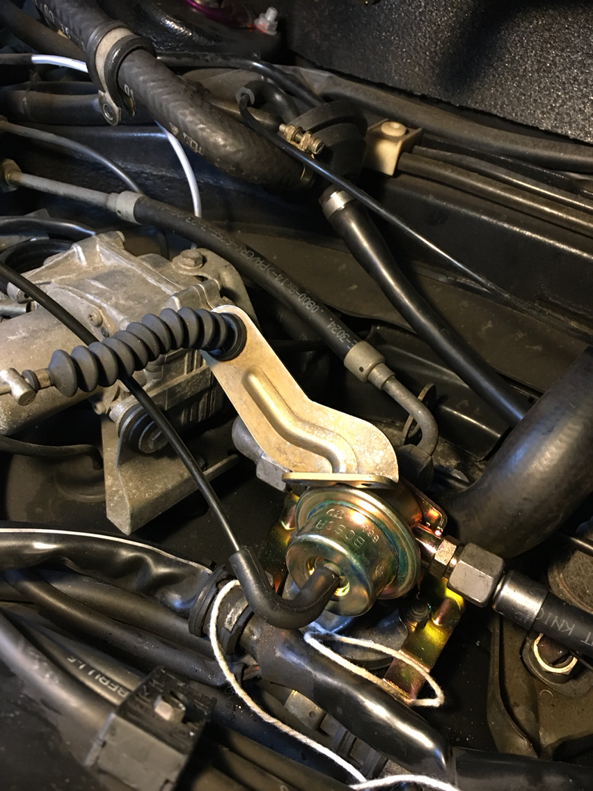
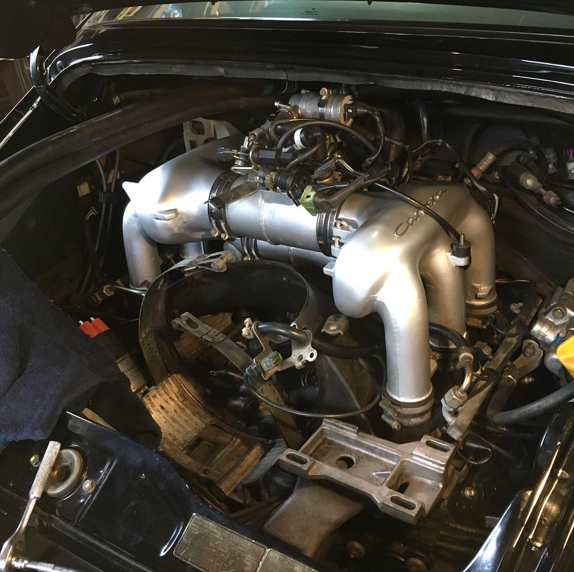
And then with that out we put in the new bracket- simple enough...bolt it to the studs and then bolt down the two things that came off the other bracket...
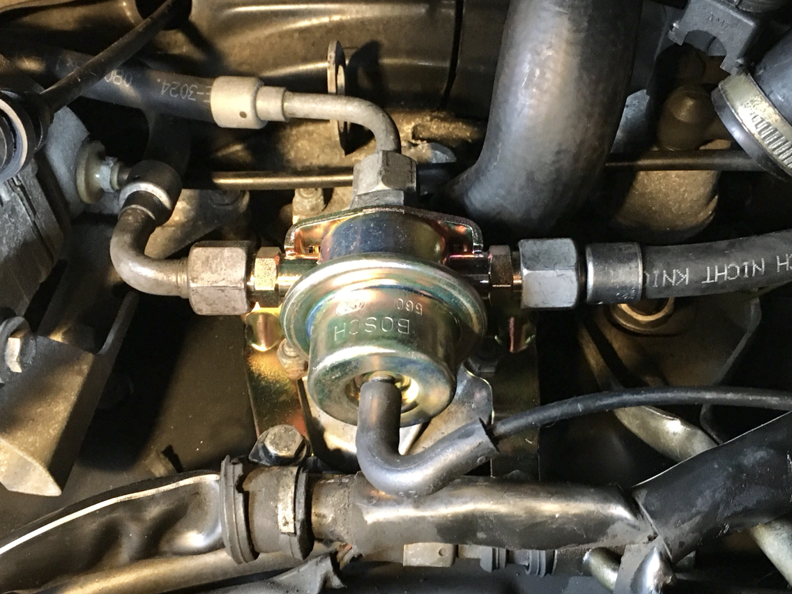
In goes the new fpr...anyone have any idea of torque for the fuel lines? I just tighten them down, but i have no clue if I'm one of those knumbknuckles I'm always bitching about at the shops that just over torque everything...so some guidance here for the future would be good. For now, these are tight and we hope it doesn't leak or we will have a fire.
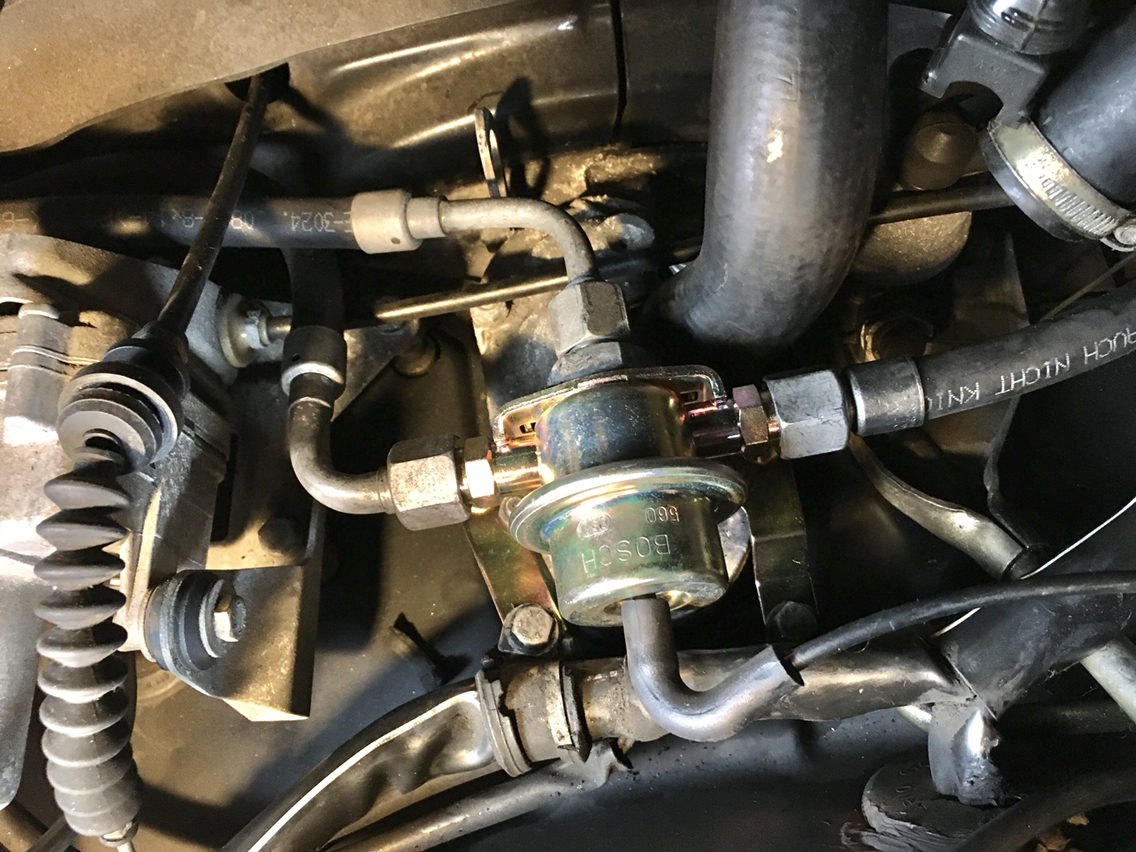
So here is a little guy that is part of the old setup. But the new has a completely different hose-
This goes to the side of the throttle body...
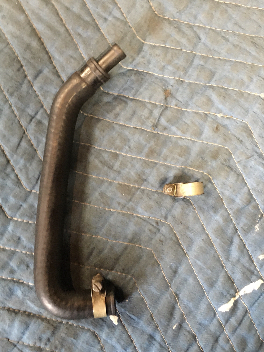
This is the hose in the car that goes to the side of the newer throttle body...
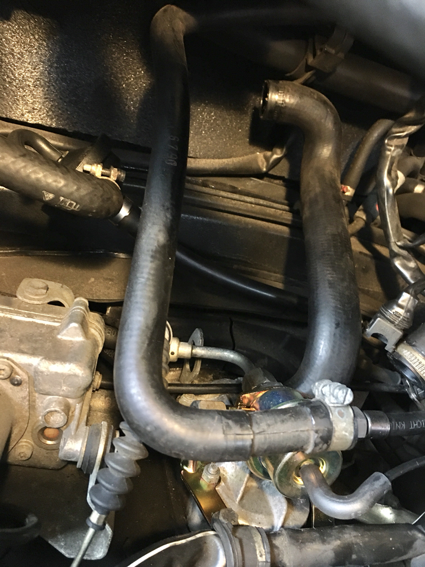
So basically the hose in the car had to be cut to meet up with the end of the old hose. You see at the end of the old hose there is a step-down fitting. So that worked out well. Snip snip and all good...
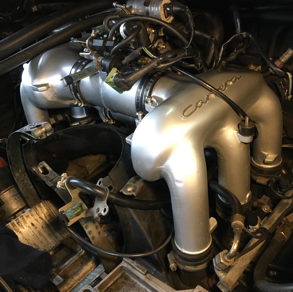
So here we are...ready?
And in the left half goes...
But nooooooooo....it has to come back out.
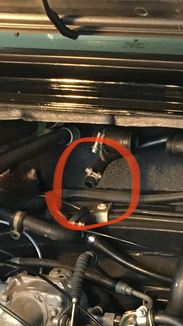
So there was the little issue of getting the throttle cable gromit into the bracket. That bracket is bolted to the back side of the throttle body- so in a blind very fiddly manner, i unbolted that from the back of the throttle body and took everything back out. Then used the string trick and got that sorted - a little dawn dishwashing liquid helps as a lubricant-
And then with that sorted- that left half went back in, that bracket rebolted to the throttle body, and then i started on vac lines and oil breather , plugs, routing wires, etc...
And....
But more on that later . My new fuel pressure regulator bracket arrived, so it was time to get some real work done "backdating" the intake system. I really wish it hadn't been years since the beginning of this project, but life and babies can really get in the way of fun- as can many other 964 and all their woes in the meantime. That said, there are a whole bunch of things that were top of mind when i began, and that have now either disappeared or surprise me when they come back to light.
First up, here is the bracket
And then when we look at the later setup, there is a bracket down there under the fpr that has mounts for the wiring harness and a fuel line
Here it is out...
And then with that out we put in the new bracket- simple enough...bolt it to the studs and then bolt down the two things that came off the other bracket...
In goes the new fpr...anyone have any idea of torque for the fuel lines? I just tighten them down, but i have no clue if I'm one of those knumbknuckles I'm always bitching about at the shops that just over torque everything...so some guidance here for the future would be good. For now, these are tight and we hope it doesn't leak or we will have a fire.
So here is a little guy that is part of the old setup. But the new has a completely different hose-
This goes to the side of the throttle body...
This is the hose in the car that goes to the side of the newer throttle body...
So basically the hose in the car had to be cut to meet up with the end of the old hose. You see at the end of the old hose there is a step-down fitting. So that worked out well. Snip snip and all good...
So here we are...ready?
And in the left half goes...
But nooooooooo....it has to come back out.
So there was the little issue of getting the throttle cable gromit into the bracket. That bracket is bolted to the back side of the throttle body- so in a blind very fiddly manner, i unbolted that from the back of the throttle body and took everything back out. Then used the string trick and got that sorted - a little dawn dishwashing liquid helps as a lubricant-
And then with that sorted- that left half went back in, that bracket rebolted to the throttle body, and then i started on vac lines and oil breather , plugs, routing wires, etc...
And....
The following users liked this post:
911Jetta (02-13-2020)
02-16-2020, 07:42 PM
#306
Race Car
Thread Starter
I know this is stupid. So do not reply and say "dude, that was stupid".
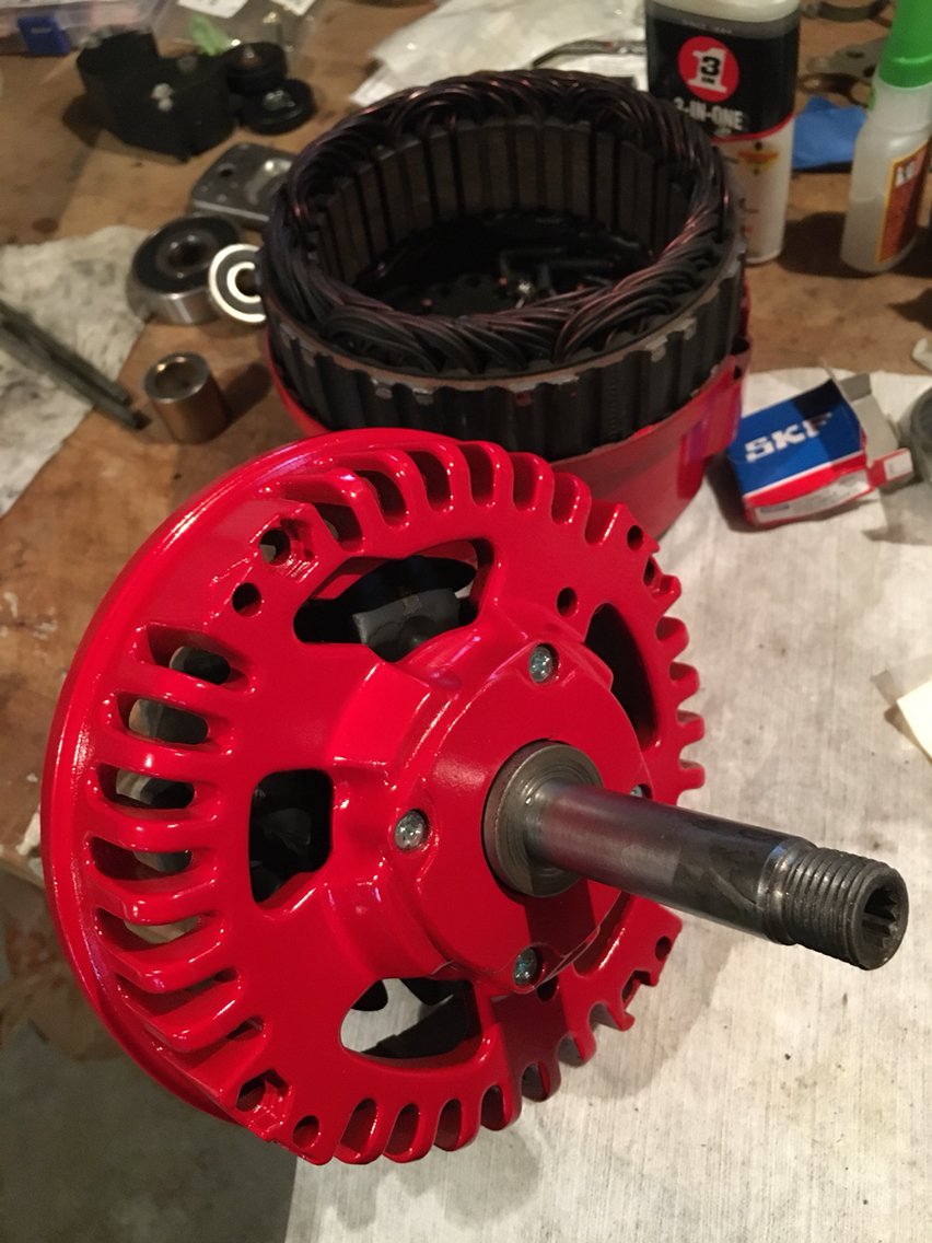
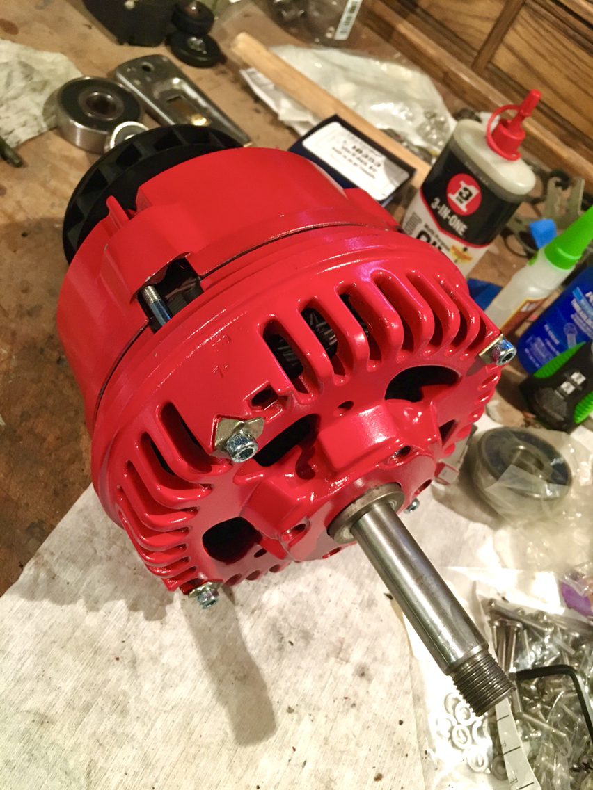
Sometimes, however, stupid is the funnest way to be...and so therefore...I painted the alternator housing red.
"If you never did you should. These things are fun and fun is good"
Dr. Seuss
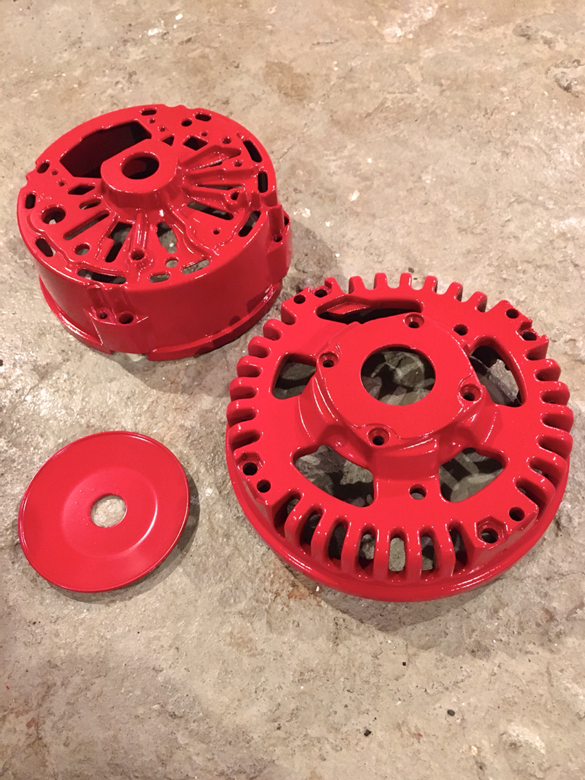
I kinda like it. I'm the only one that will ever see it - and I'm sure it'll now not be accepted as a core, but it's pretty.
So on to the reassembly. Now that the correct size bearings have arrived. Keep in mind, i did not have to check the diodes on this alternator- it was easily pumping out 14 volts prior. The bearings had a ton of play when i took it out, so that's the reason for the rebuild. I'm not much of an electrician, so at the point when the unit is really failing, i may be sol and have to swap for a new one. So this rebuild is just bearings, tolerance cup and voltage regulator- but i thew my old voltage regulator back in. ( i have another alternator sitting in a box that needs a rebuild, so I'll use my extra bearings and regulator for that one.
Anyway- aside from all that and those words- the only other thing to mention is it would be a good idea to either machine the slip rings or to solder new slip rings on and machine those. But again- this isn't a full rebuild. This is the rebuild 99% of us should be doing when we think we need a rebuild. Aka- the easy way.
So here we go:
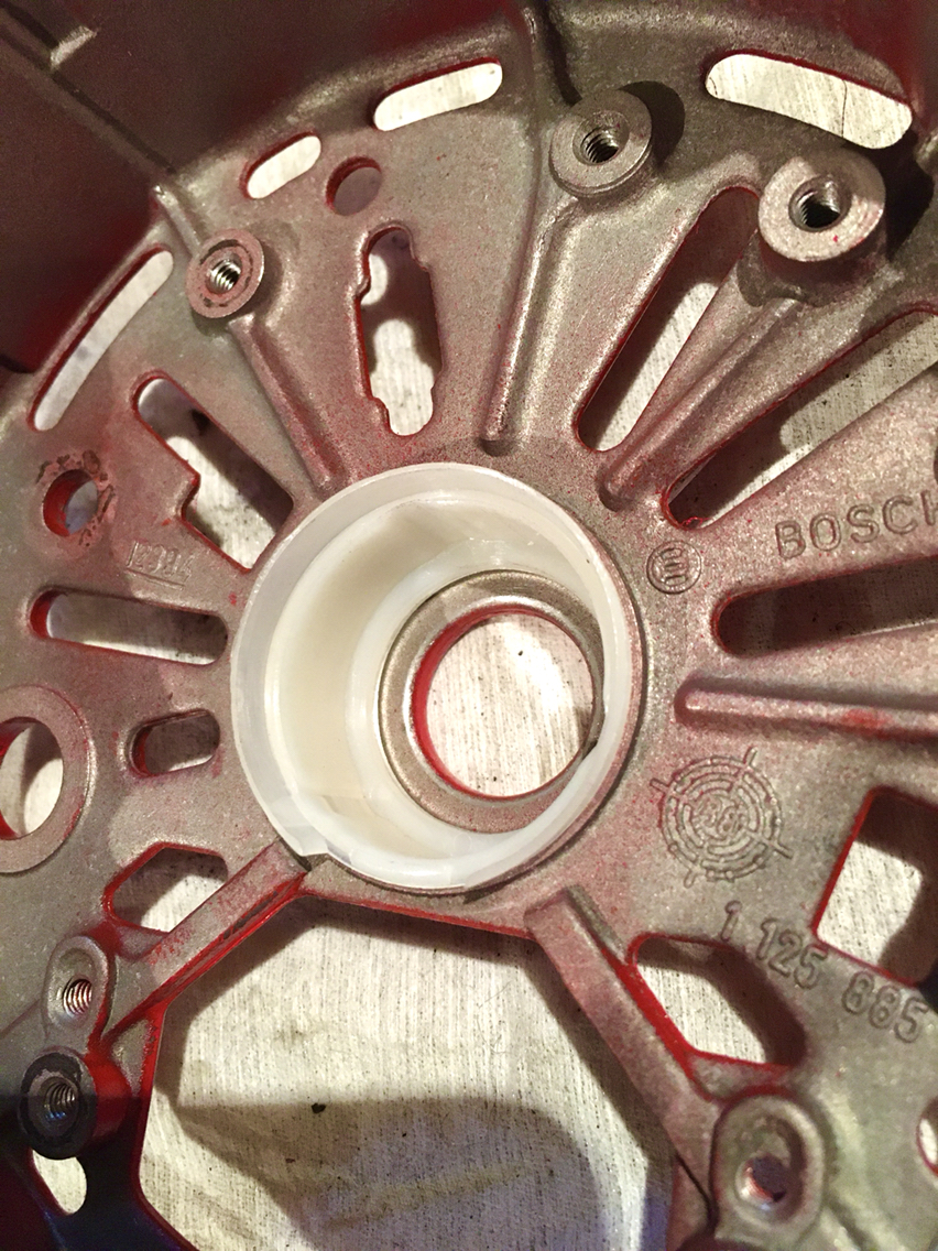
Press in the tolerance cup. This should press in with your fingers.
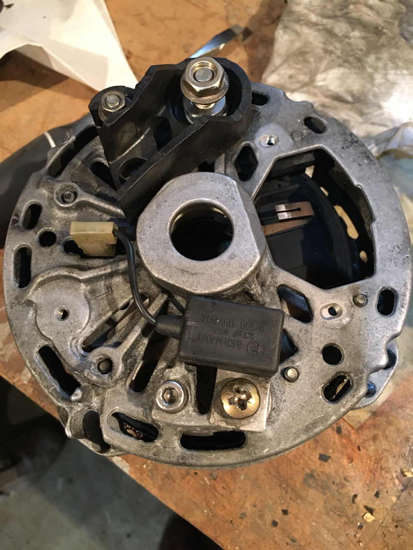
Then toss in the rectifier plate- five screws hold that to the back half of the housing. I replaced my screws with new stainless.
Now put that aside and press the bearings onto your armature...use the spacers that came off w the bearings to lend a hand- and a deep well socket maybe for a press tool. We aren't using a lot of force here. When you press- you are only pressing the inner bearing race - never hammer on a bearing, and always stop when you reach the end. Don't force anything. It's a bearing, it's only your friend if you treat it well.
Don't forget the retaining plate behind the larger bearing- orient it correctly.
Then insert the armature into the front half of the housing and screw in the retaining plate.
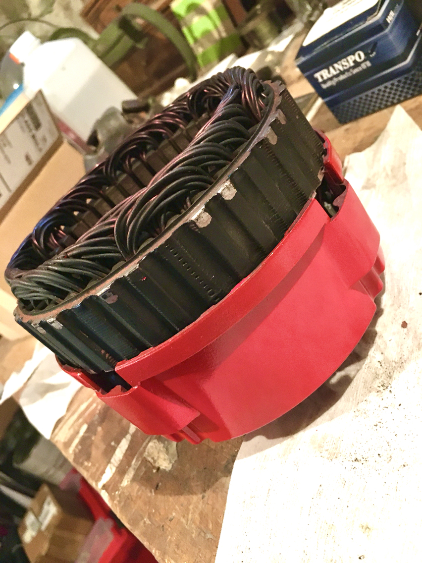
And now we are going to complete the halves...this can be a bad marriage or a good marriage - it's up to you. If it's a bad marriage, there will be no screwing.
Allow me to explain...this will only make sense if you are trying to put these together...the screws that hold the two halves together have to go all the way through and you have to orient the stator to allow for this.
And now we can screw the two halves together.
I swapped out the oem Phillips head bolts for Allen bolts. Unfortunately the bolts i bought from McMaster didn't have enough thread, so out came the threading tools...and new threads were cut.
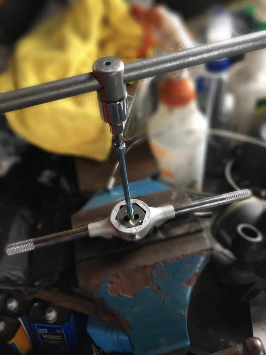
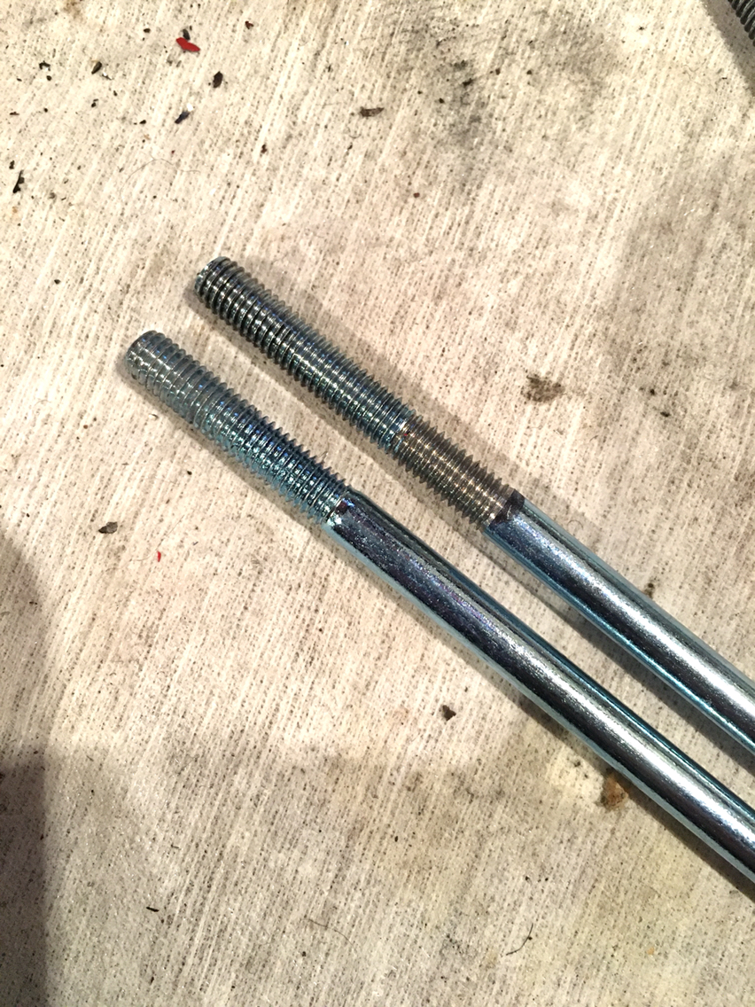
So in they went and i worked my way around the bolts one at a time, couple turns at a time, until the two halves were a happy marriage. I was going to make another screwing joke here, but i spared you. Maybe thank me later.
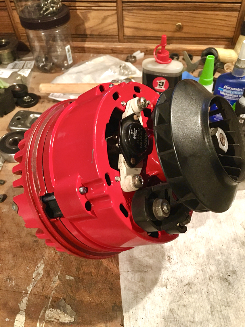
So then just add the do-dads to the back of the unit. Anything that needs to ground to the housing, make sure to scrape the paint off if you did something silly like paint the housing...
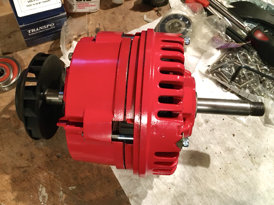
And so here we have the finished product...
Tomorrow my fan arrives. The fan housing is still soaking in stripper- it's been weeks. Way too cold for stripper to work well. So it's taking forever. So once that is done and i paint the housing and the fan, I'm ready to finish the reassembly. And then we start it up and see if it'll run. I'm hoping that i don't have any gas leaks after replacing the fuel filter and the fuel pressure regulator- how tight do those fittings need to be?
Sometimes, however, stupid is the funnest way to be...and so therefore...I painted the alternator housing red.
"If you never did you should. These things are fun and fun is good"
Dr. Seuss
I kinda like it. I'm the only one that will ever see it - and I'm sure it'll now not be accepted as a core, but it's pretty.
So on to the reassembly. Now that the correct size bearings have arrived. Keep in mind, i did not have to check the diodes on this alternator- it was easily pumping out 14 volts prior. The bearings had a ton of play when i took it out, so that's the reason for the rebuild. I'm not much of an electrician, so at the point when the unit is really failing, i may be sol and have to swap for a new one. So this rebuild is just bearings, tolerance cup and voltage regulator- but i thew my old voltage regulator back in. ( i have another alternator sitting in a box that needs a rebuild, so I'll use my extra bearings and regulator for that one.
Anyway- aside from all that and those words- the only other thing to mention is it would be a good idea to either machine the slip rings or to solder new slip rings on and machine those. But again- this isn't a full rebuild. This is the rebuild 99% of us should be doing when we think we need a rebuild. Aka- the easy way.
So here we go:
Press in the tolerance cup. This should press in with your fingers.
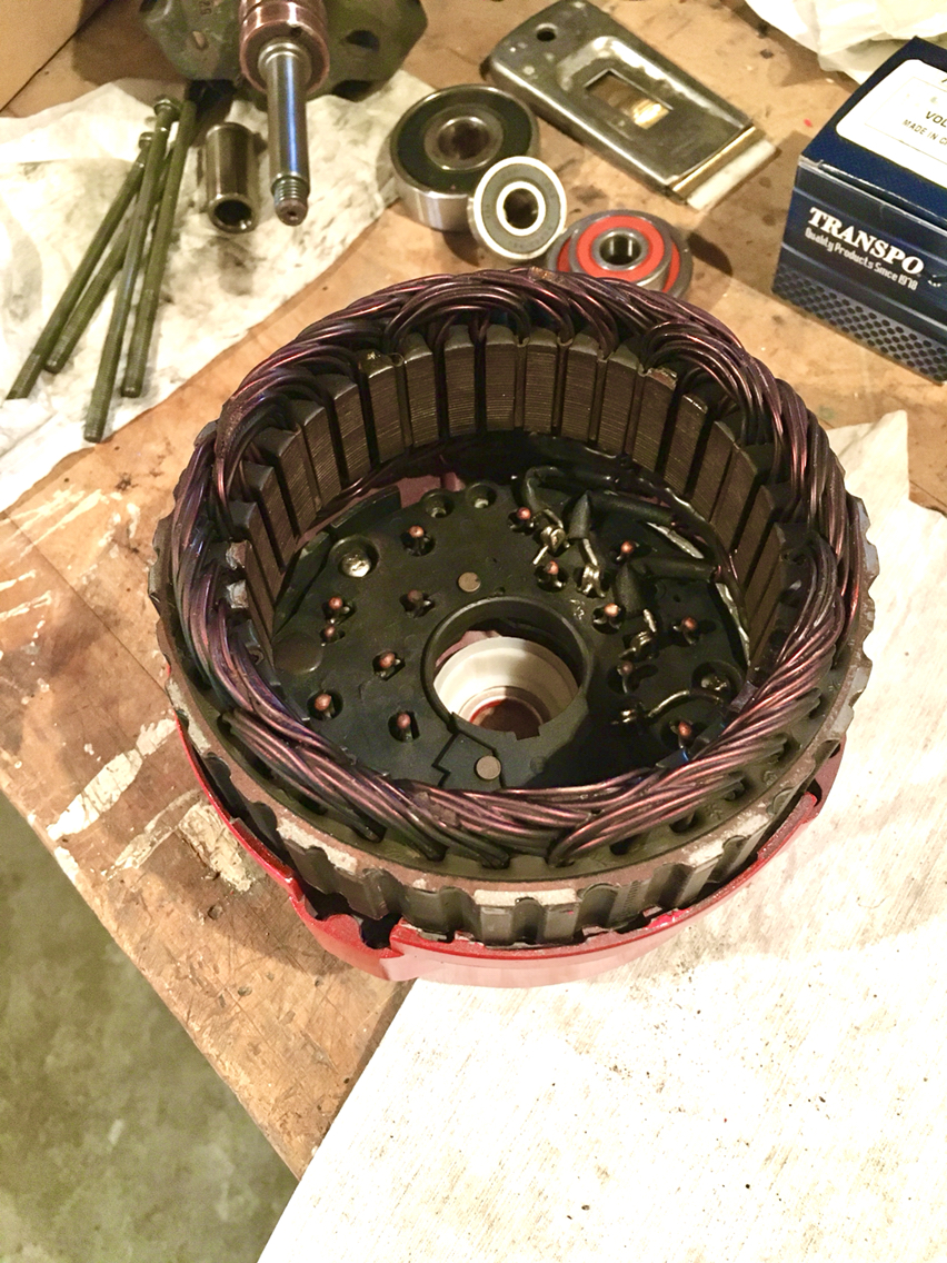
Then toss in the rectifier plate- five screws hold that to the back half of the housing. I replaced my screws with new stainless.
Now put that aside and press the bearings onto your armature...use the spacers that came off w the bearings to lend a hand- and a deep well socket maybe for a press tool. We aren't using a lot of force here. When you press- you are only pressing the inner bearing race - never hammer on a bearing, and always stop when you reach the end. Don't force anything. It's a bearing, it's only your friend if you treat it well.
Don't forget the retaining plate behind the larger bearing- orient it correctly.
Then insert the armature into the front half of the housing and screw in the retaining plate.
And now we are going to complete the halves...this can be a bad marriage or a good marriage - it's up to you. If it's a bad marriage, there will be no screwing.
Allow me to explain...this will only make sense if you are trying to put these together...the screws that hold the two halves together have to go all the way through and you have to orient the stator to allow for this.
And now we can screw the two halves together.
I swapped out the oem Phillips head bolts for Allen bolts. Unfortunately the bolts i bought from McMaster didn't have enough thread, so out came the threading tools...and new threads were cut.
So in they went and i worked my way around the bolts one at a time, couple turns at a time, until the two halves were a happy marriage. I was going to make another screwing joke here, but i spared you. Maybe thank me later.
So then just add the do-dads to the back of the unit. Anything that needs to ground to the housing, make sure to scrape the paint off if you did something silly like paint the housing...
And so here we have the finished product...
Tomorrow my fan arrives. The fan housing is still soaking in stripper- it's been weeks. Way too cold for stripper to work well. So it's taking forever. So once that is done and i paint the housing and the fan, I'm ready to finish the reassembly. And then we start it up and see if it'll run. I'm hoping that i don't have any gas leaks after replacing the fuel filter and the fuel pressure regulator- how tight do those fittings need to be?

 . Another task well-documented, thanks!
02-17-2020, 04:37 PM
. Another task well-documented, thanks!
02-17-2020, 04:37 PM
#309
Instructor
Thanks Rob for another detailed report. Just a suggestion when you are in the alternate universe and start a thread on intake madness, why not separate each topic into their own heading so lazy soles like me can find things easier.
Cheers
Cheers
02-17-2020, 08:07 PM
#311
Race Car
Thread Starter
Originally Posted by jwbavalon
Thanks Rob for another detailed report. Just a suggestion when you are in the alternate universe and start a thread on intake madness, why not separate each topic into their own heading so lazy soles like me can find things easier.
Cheers
Cheers
This happened during suspension madness too- most of that thread has nothing to do with suspensions...lol.
The following users liked this post:
964George (03-23-2020)
02-17-2020, 09:42 PM
#312
Rennlist Member
Fair point...I'm still in the intake madness mode...and in this case the alternator is out because of that...so it just happened because of the bad bearings i found once it was out.
This happened during suspension madness too- most of that thread has nothing to do with suspensions...lol.
This happened during suspension madness too- most of that thread has nothing to do with suspensions...lol.
 02-22-2020, 08:13 PM
#314
Race Car
Thread Starter
My fan housing came back from the strippers today. (Thank you BigMike!)
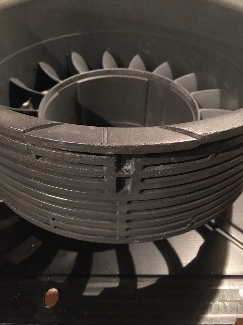
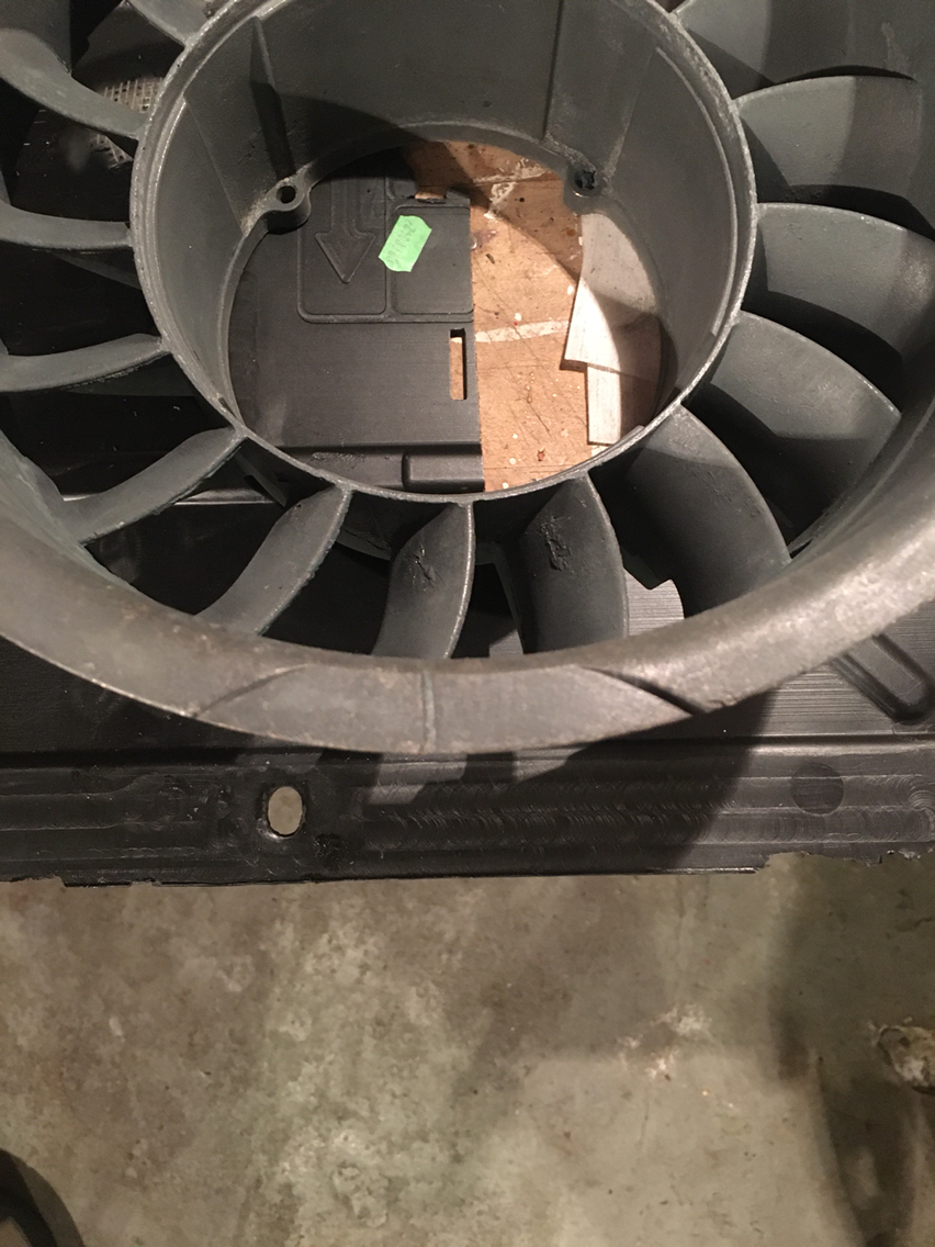
So now that the paint/powder coat is gone- something I'll never do again btw - i am looking at the housing and noticed the tdc Mark is not in the center of the cutout area. Is this normal?
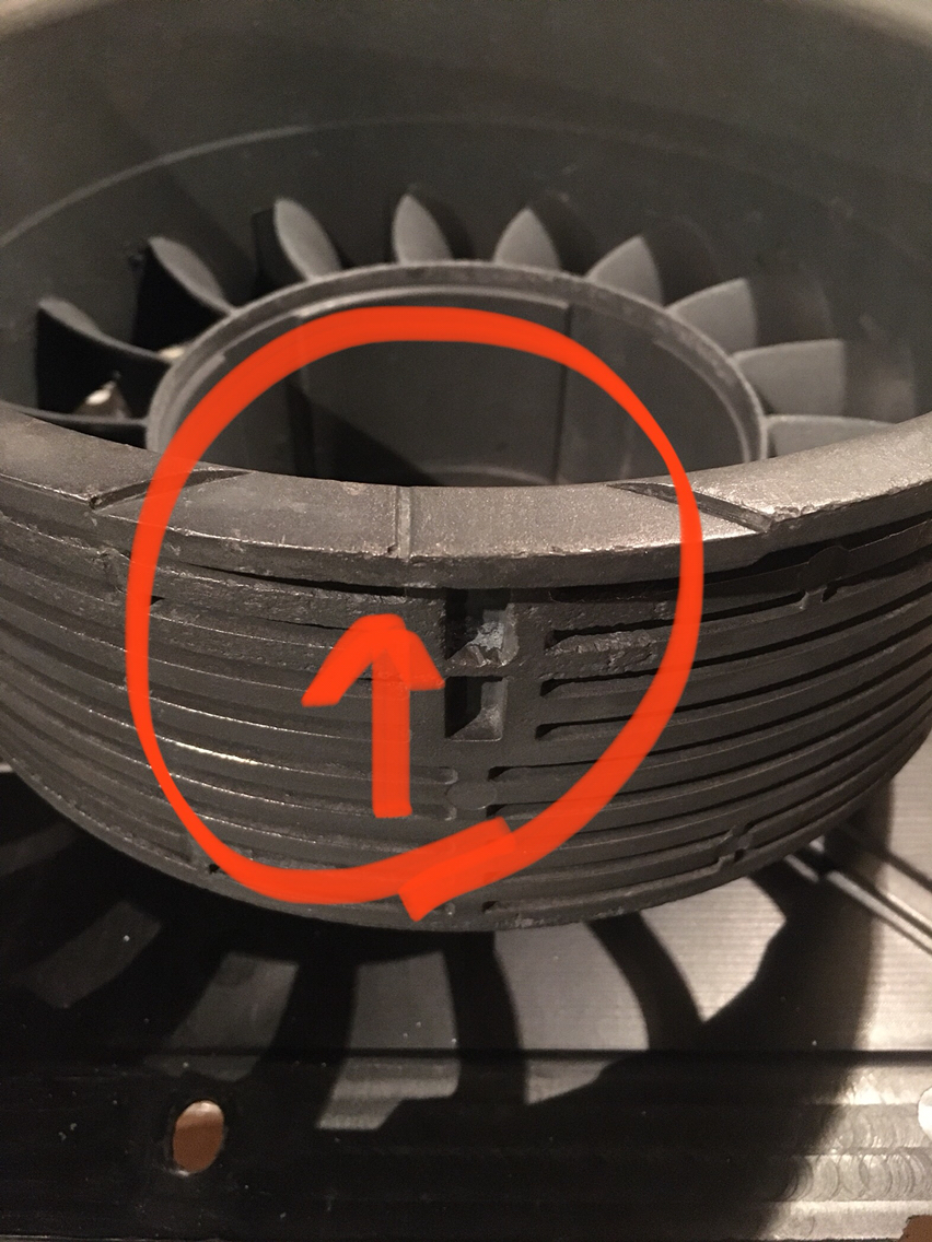
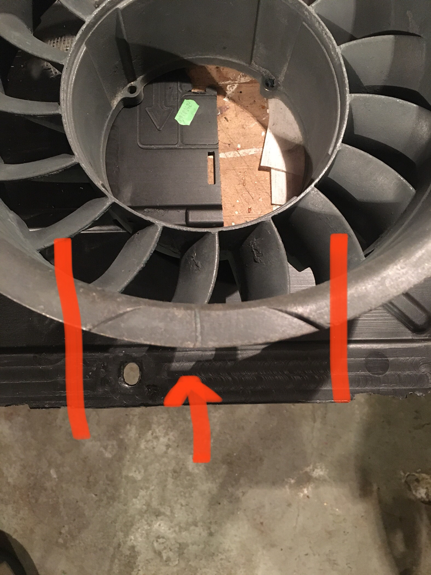
It just never occurred to me to look. So I'm curious if they are all the same?
So now that the paint/powder coat is gone- something I'll never do again btw - i am looking at the housing and noticed the tdc Mark is not in the center of the cutout area. Is this normal?
It just never occurred to me to look. So I'm curious if they are all the same?
02-23-2020, 03:26 AM
#315

Mines the same! I gotta figure out what I�m going to do with all the mag parts too. Not so easy to find places that strip etc here unfortunately. In fact my engine rebuild is hung up on this very point .....
pete
pete