

Intake madness. Teardown begins....
 02-03-2020, 06:21 PM
#286

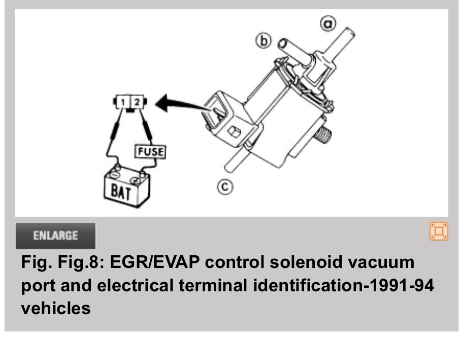
If you look at the control solenoid you'll see a black plug it just a cap to keep dirt out but it lets vacuum release so the flap can close. I know on my car this operates at 5500 RPM's on the gt3 intake I have now vacuum pulls the flap closed it's spring loaded to open it. I guess they do this so when the engine is low on vacuum the flap stays open.
 02-03-2020, 06:34 PM
#287
 02-04-2020, 03:55 PM
#289
Race Car
Thread Starter
Ok so out goes the plug and the original - which does not come with the replacement unit, I'll just pop onto the new one...and good to go.
As to how the resonance flap is actuated- yes it's correct that it's actuated by vacuum. However- it's only actuated by vacuum once the wot switch is pressed- which then this little unit switches open- and the vacuum that is used is then coming from the vacuum canister. So in effect, the resonance flap is electronically controlled in that sense.
I'd still like to figure a way to see the rear port in use- so maybe I'll attach a balloon to it after i get everything back together and see what it's doing.

 02-05-2020, 12:09 AM
#291
Race Car
Thread Starter
Found this:
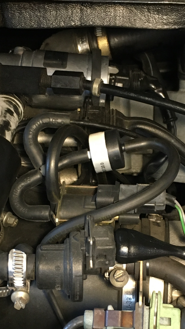
So here is the setup in the car...
Which means that - in our case - with power off, the vacuum is being supplied to the vacuum canister from the intake, and with power on, the vacuum is then traveling through from the intake and the vac canister to the resonance flap.
Then we would have to assume that on power off, the vent on the right hand side of the solenoid in the photo allows the pressure to dissipate and the resonance flap closes by its return spring.
02-05-2020, 09:21 AM
#292
Found this:
Attachment 1311791
Which means that - in our case - with power off, the vacuum is being supplied to the vacuum canister from the intake, and with power on, the vacuum is then traveling through from the intake and the vac canister to the resonance flap.
Then we would have to assume that on power off, the vent on the right hand side of the solenoid in the photo allows the pressure to dissipate and the resonance flap closes by its return spring.
 Nice! Your intake is looking too good to be caught up on a small technical speed bump and possibly a loss of low end power.
Fyi.. I remember someone on this thread asking about the seals/bearings for the resonance shaft on the plastic intake. It uses brass bushings and 8x12x3 oil seals.
02-05-2020, 10:19 AM
#293
Race Car
Thread Starter
That's interesting- i was going to pull the one apart that i just took off the car and check that out. Do you happen to know a source for those seals and bushings?
02-05-2020, 10:32 AM
#294
Oil Seal 8X12X3 (2 PCS) Oil Seal Grease Seal VG |EAI Rubber Covered Outer Diameter with Sealing Lip 8mmX12mmX3mm | 0.315"x0.472"x0.118"


The following users liked this post:
kos11-12 (08-10-2022)
02-05-2020, 11:16 AM
#295
Technical Guru
Rennlist Member
Rennlist Member
As to how the resonance flap is actuated- yes it's correct that it's actuated by vacuum. However- it's only actuated by vacuum once the wot switch is pressed- which then this little unit switches open- and the vacuum that is used is then coming from the vacuum canister. So in effect, the resonance flap is electronically controlled in that sense.
02-05-2020, 10:50 PM
#296
Race Car
Thread Starter
No Jason...the clicking of the Wot switch sends the electrical signal to the vacuum solenoid that opens the vacuum to the resonance flap...
Sorry if that got confusing. Some of this and the reasons behind it, I'm learning as i go along. It's a strange mixture of vacuum used for performance reasons and also for environmental reasons. So it's good to finally put some documentation down and get the systems sorted. They seem so complicated until as we see now, they really aren't all that complicated in the end.
Sorry if that got confusing. Some of this and the reasons behind it, I'm learning as i go along. It's a strange mixture of vacuum used for performance reasons and also for environmental reasons. So it's good to finally put some documentation down and get the systems sorted. They seem so complicated until as we see now, they really aren't all that complicated in the end.
02-06-2020, 11:57 AM
#297
Technical Guru
Rennlist Member
Rennlist Member

The description is accurate enough that you can map what's written in the documentation to the actual ECU source code;
PHP Code:
; ---------------------------------------------------------------------------

; REV-LIMITER


@@20:

    mov A, #0xA

    movc A, @A+DPTR

    mov R2, A ; 61CB = 0x03

    mov A, #9

    movc A, @A+DPTR ; 61CA = 0xA3 = 6520

    add A, R2

    cjne A, RAM_RPM_VALUE, @@21 ; Turn Fuel off at 6640


@@21:

    jc @@TurnFuelOff


    mov A, #8

    movc A, @A+DPTR ; 61C9 = 0x87 = 5400

    cjne A, RAM_RPM_VALUE, @@22 ; Close Resonance flap at 5400RPM


@@22:

    jnc @@25


    add A, R2 ; 61CB = 0x03

    cjne A, RAM_RPM_VALUE, @@23 ; Open Resonance Flap at 5520rpm


@@23:

    jnc @@27


    mov A, #9

    movc A, @A+DPTR ; A = 0xA3 -- Turn Injectors On

    cjne A, RAM_RPM_VALUE, @@24


@@24:

    cpl C

    jnc @@27


@@25:

    cpl C


@@TurnFuelOff:

    mov SOLENOID_RESONANCE, C ; C = TRUE if RPM > 6640


@@27:

    mov P2, #0x7E ; '~'

    mov R0, #0x5A ; 'Z' ; 7E5A

    movx A, @R0

    jnb ACC.6, @@28


    setb SOLENOID_RESONANCE


@@28:

    jnb STATUS_STARTING, @@30


@@29:

    clr SOLENOID_RESONANCE


@@30:

    ret
02-06-2020, 06:24 PM
#298
Love me some assembly language, but how do you have this and is this accessible somewhere? It so odd to see source code with developer comments for a bosch EFI.
02-06-2020, 08:52 PM
#299
Race Car
Thread Starter
So now we need to review what actually happens when the wot switch is pressed. I think we always had the understanding here that it controlled the resonance flap.
I have that service technik somewhere. I'll have to look that up.
Fwiw/ the throttle body in that pic in the service technik you posted is the very early version that has the dual resonance flaps. One on each side. That seems to have been dropped shortly after production began. Perhaps there wasn't enough vacuum to open the flaps on a consistent basis? With two springs the system was a little heavy. I have one of those old units here.
02-06-2020, 10:05 PM
#300
Race Car
Thread Starter
So- here is the full diagram of the system from that tech manual up above. I knew i had a copy of that somewhere. Found it buried in old notebooks...

And there is another page further back that describes the adjustment of the throttle off switch and the wot switch...
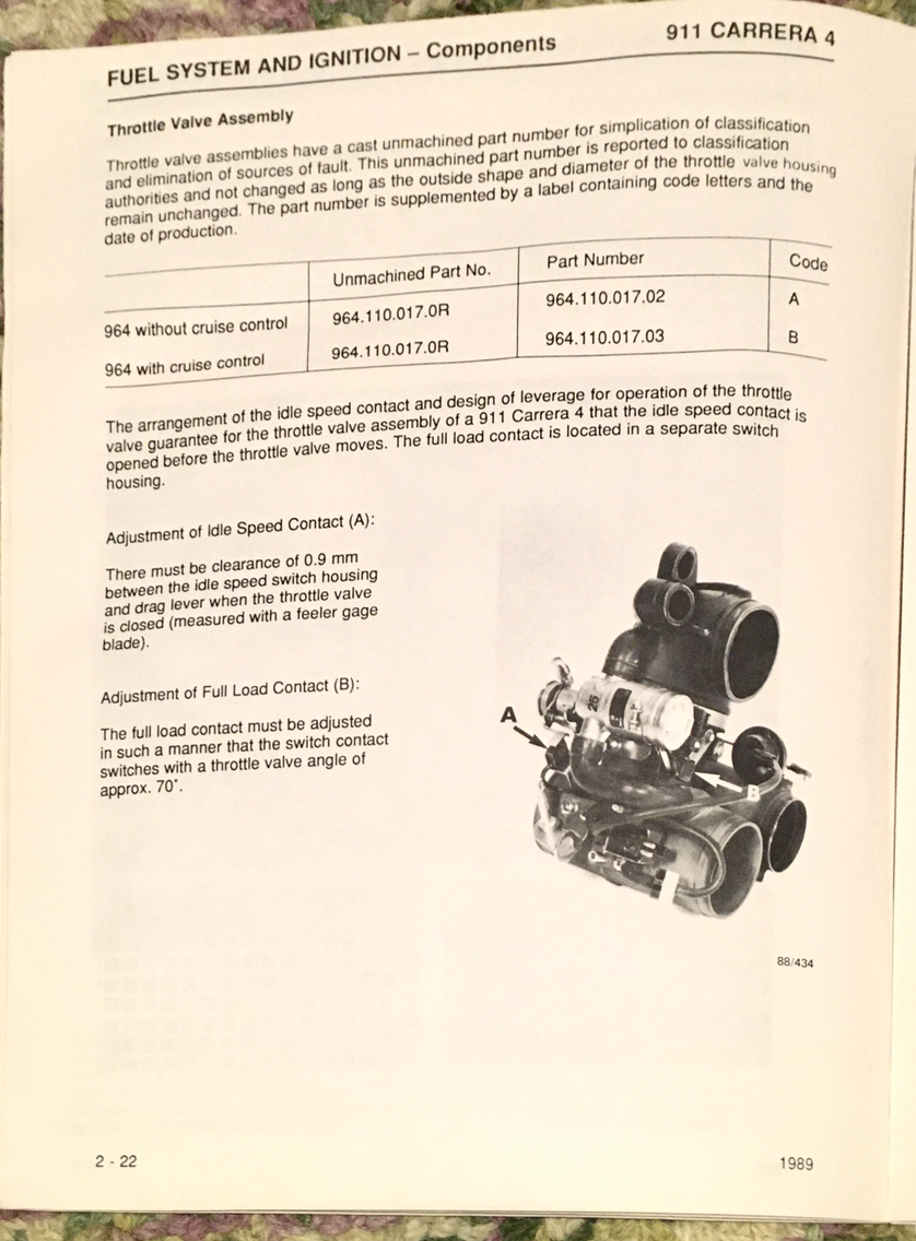
And there is another page further back that describes the adjustment of the throttle off switch and the wot switch...