When you click on links to various merchants on this site and make a purchase, this can result in this site earning a commission. Affiliate programs and affiliations include, but are not limited to, the eBay Partner Network.
I have standard bulbs in my H4s.
I don't get the high beam indicator on any time other than when the high beams are on.
I will get you some info on what wires go where when I can (later today or tomorrow).
Thanks Joe. I didn't have the glowing hi-beam indicator with the Halogen 9004 bulbs, it only started when I installed the LED replacements, so maybe it's just an issue with using LED bulbs, since Ron's completely different LED headlight setup does the exact same thing. I would still like to double-check the wiring if you have the connection order with a reference to the flat side of the 9004 bulb assembly itself. Even a simple drawing or photo would suffice.
Forgot all about this until just now when I read your post.
Sorry.
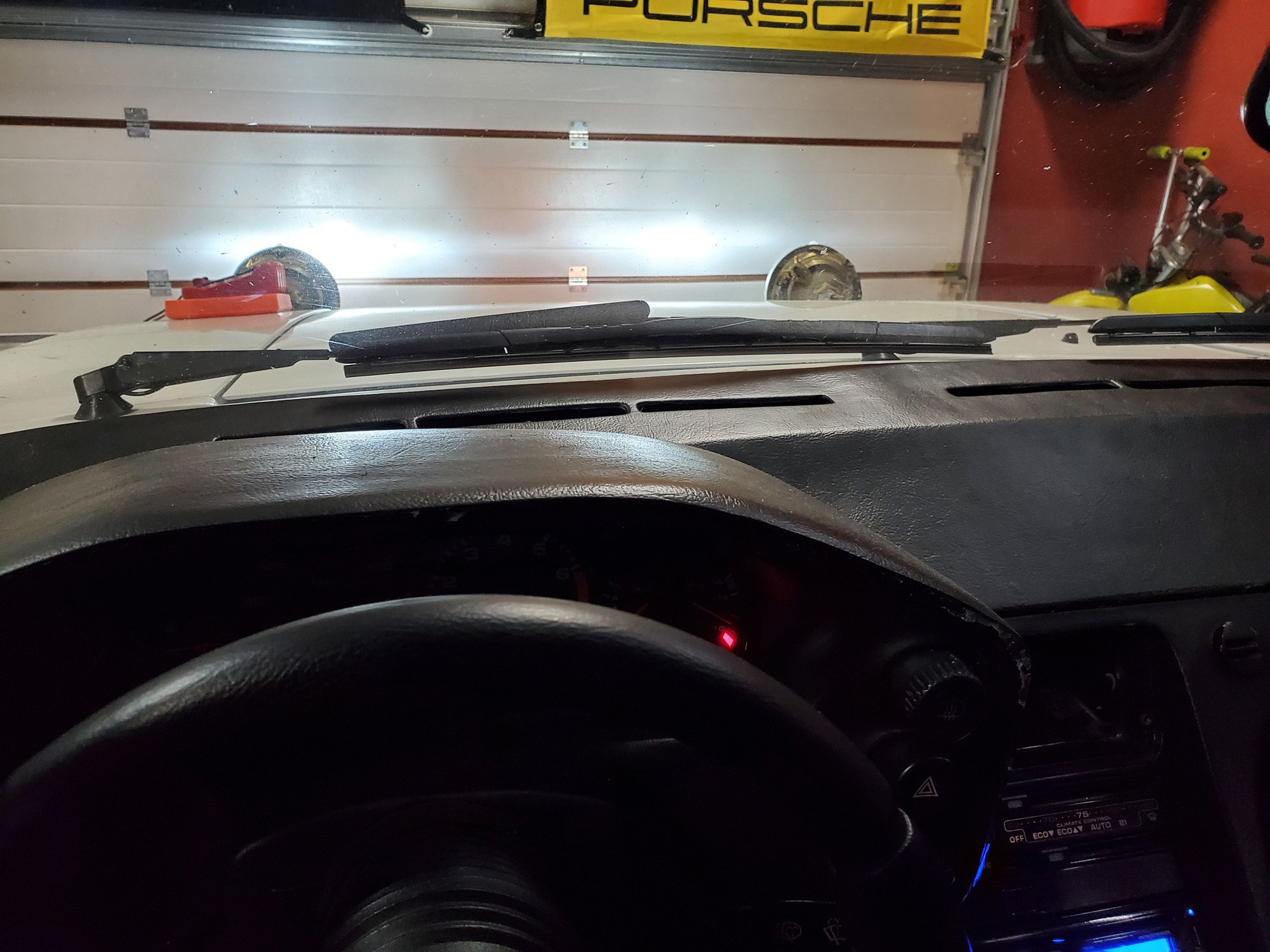
From the driver's seat:
3 wires, left top & right.
Left is brown (ground). Top is yellow, right is white.
Thanks, but I'm not sure how much help that's going to be. In my 9004 LED bulbs, all the contacts are in a straight line across the middle of the bulb. I have a feeling a PO installed a non-standard light bulb and because of that cut off the normal like connector as when I took them apart I had 3 blue insulator crimp on connectors on the 3 wires rather than a normal shaped headlight plug. As an extra bonus, they had regular width female connectors on them, and how they installed those onto the 3 pins without having any 2 of them short against each other is kind of a miracle. I replaced those with new one and used the proper skinny width versions that mate up to the width of the male spades on the headlight bulb. Mine also have those thick clear insulating covers on them like what you find for the small terminal when hooking up an audio speaker. I guess I may have to remove a bulb and play around with supplying 12v and ground to it to determine what sequence the wires should actually be hooked up in.
So, simpler question (maybe), obviously brown is the ground. I'm assuming I have that one right since the LEDs are actually working and they require proper polarity. The question is which wire is the low beam white or yellow and which wire is the high beam white or yellow?
I'll be pulling the covers off again this weekend to fix the bulb aim so good time to also check the connection pins.
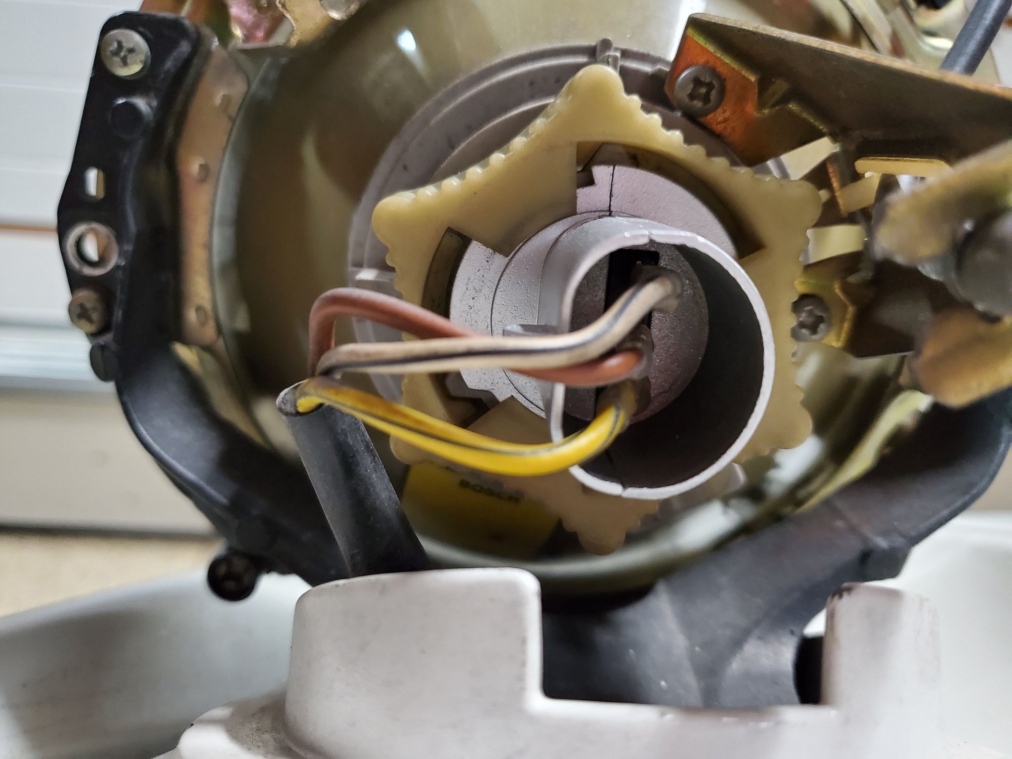
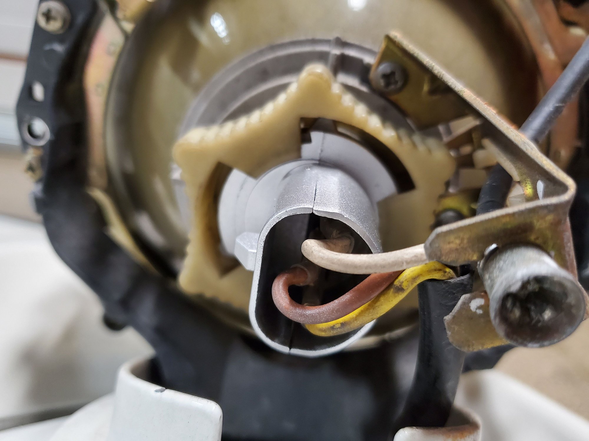
I resolved the headlight issue. Took one of the bulbs out and over to a spare battery I had with test leads. Played around with using different pin combinations for ground and low beam and high beam. Actually thought the led bulb would only light with the proper ground pin connected, but that is not the case with these - any way you connect the circuit they will illuminate. Also took a meter and tested the connector wiring to determine that the yellow wire is the low beam and the white wire is the high beam. Also, the low beam wire stays energized with 12v on it both with the stalk in the low and high beam positions, so the high beams use the low beans and then add to them the high beams. Some lights actually switch from the low beam to the high beam like those in my pickup, but not the 928, I guess. I put on a pair of sunglssses so I could look at the headlight bulb out of the housing to see what the chipsets were actually doing with the different wire combinations. Each side of the led bulb has two runs of 3 led chips. I found a combination that lit one pair of chips with 12v applied to one terminal and the other pair of chipsets with 12v applied to the other terminal, so all the chipsets are now illuminated with the high beams on and half of them with the low beams on. Ground is the center terminal.
So, installed the bulb back into the car and connected the wires and tested them. Found I had the low and high beam wires reversed for the way the bulbs work with the reflector housing so swapped them and tested again.
Now all are working properly and the glowing high beam light with the low beams on is also gone.
Also re-aimed them lower. We'll see how they work next time it's out in the dark.
Had a noisy hatch issue and I will be installing a keyless electric lock kit into the car when I have the door panels and console out, like I did in the Spyder. This time I bought a kit that has a provision for a trunk pop instead of just the doors, so my plan was to get a hatch receiver from a later car that has the trunk pop mechanical arm on it and somehow hook that arm up to an electric solenoid that cam pull the arm and pop the hatch.
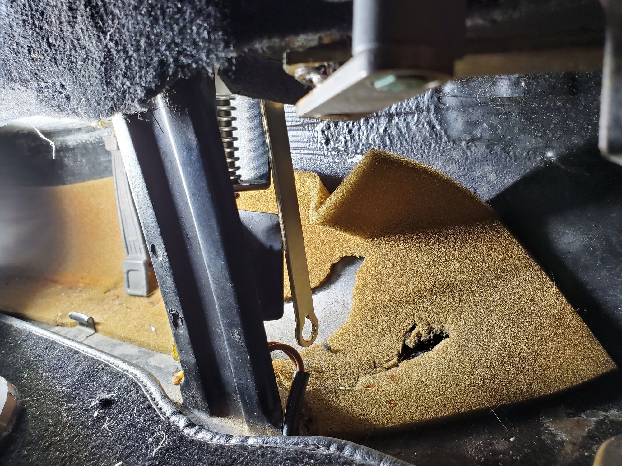
So today I decided to at least install the new receiver. As all these projects go, it wasn't just a drop in. To retrofit the newer receiver into an older car, there isn't clearance at the front edge for the hinged release mechanism or on the DS for the mechanical arm.
Took out the Demel and air body saw to create the needed clearance so the receiver hinge could fit into the slot and the arm to have clearance to move once installed.
The top level of the sheet metal is double thickness, then I had to trim and file the insert piece that receives the threaded fasteners but allows for some positional adjustability.
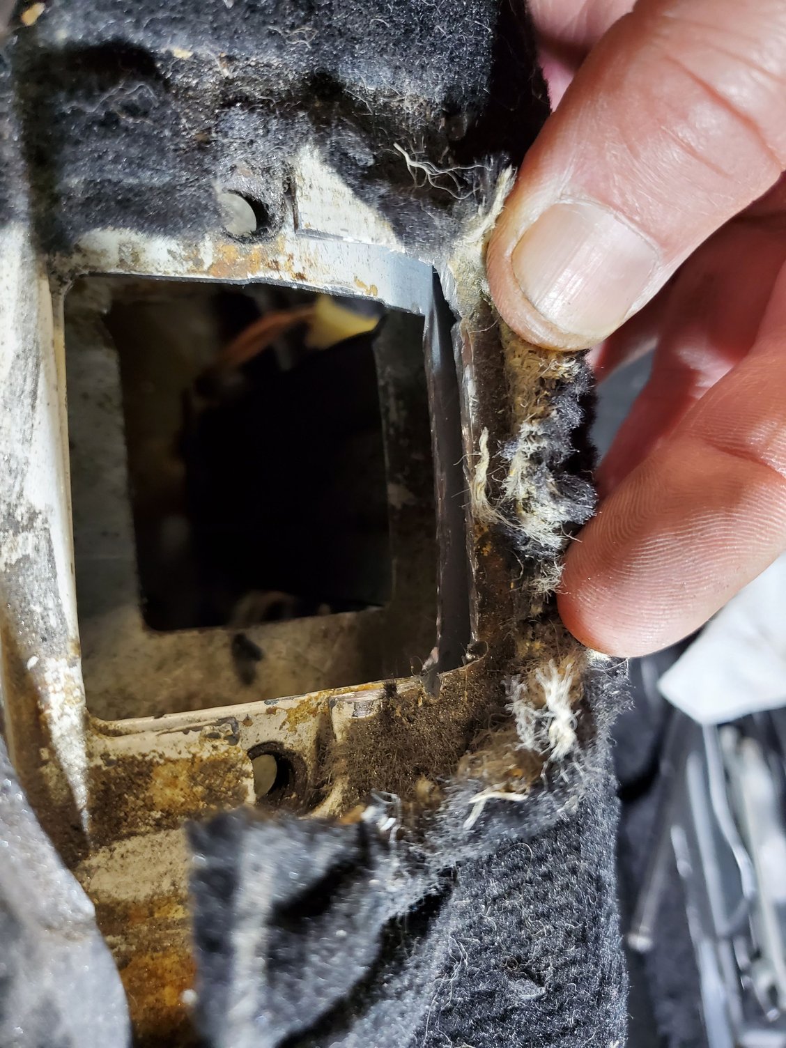
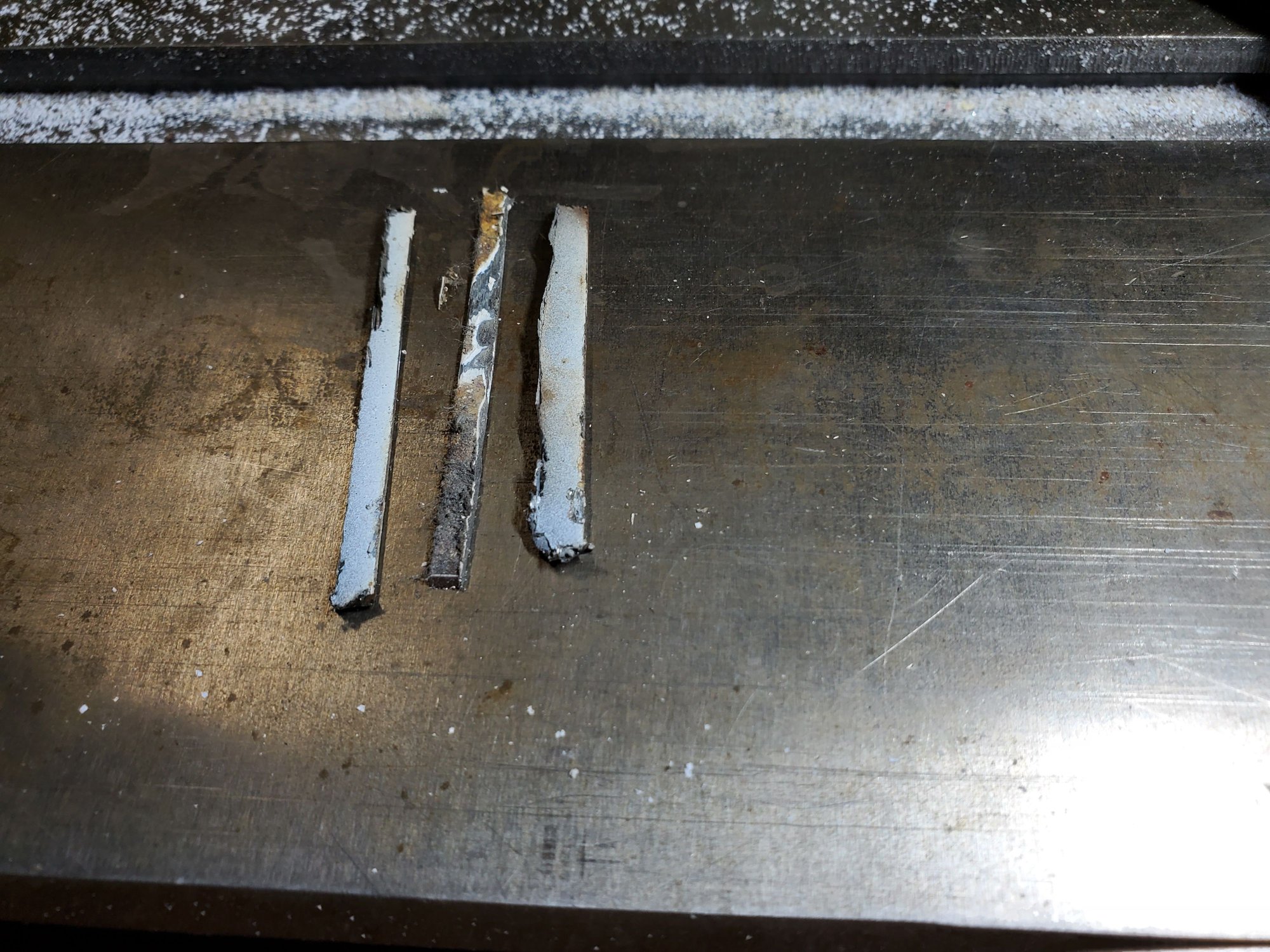
So trimmed away 3 small metal strips. These are the double ply front edge of the top sheet metal and the front edge od the floating square under that. The is actually a slot at the rear of the assembly for the floating piece to slide out, but the bumper has to be off to do that - not happening - trimmed it in place holding it steady with some upward force from a short pry bar.
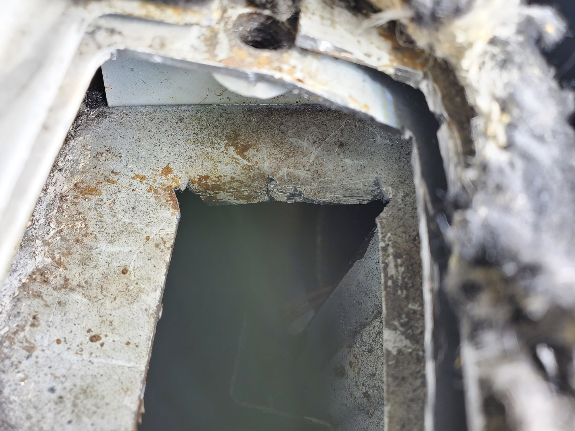
Then there's another square opening below these that is also the same size as the top opening, so that would make the latch receiver have to be offset to the passenger side for the release arm to move freely. No way to get a Dremel into that area to do a straight cut without a surgical DaVinci robot so I created a 3mm or so angled cut in those two corners with the air body saw, then took a chisel and hammer and bent the metal flap down and out of the way.
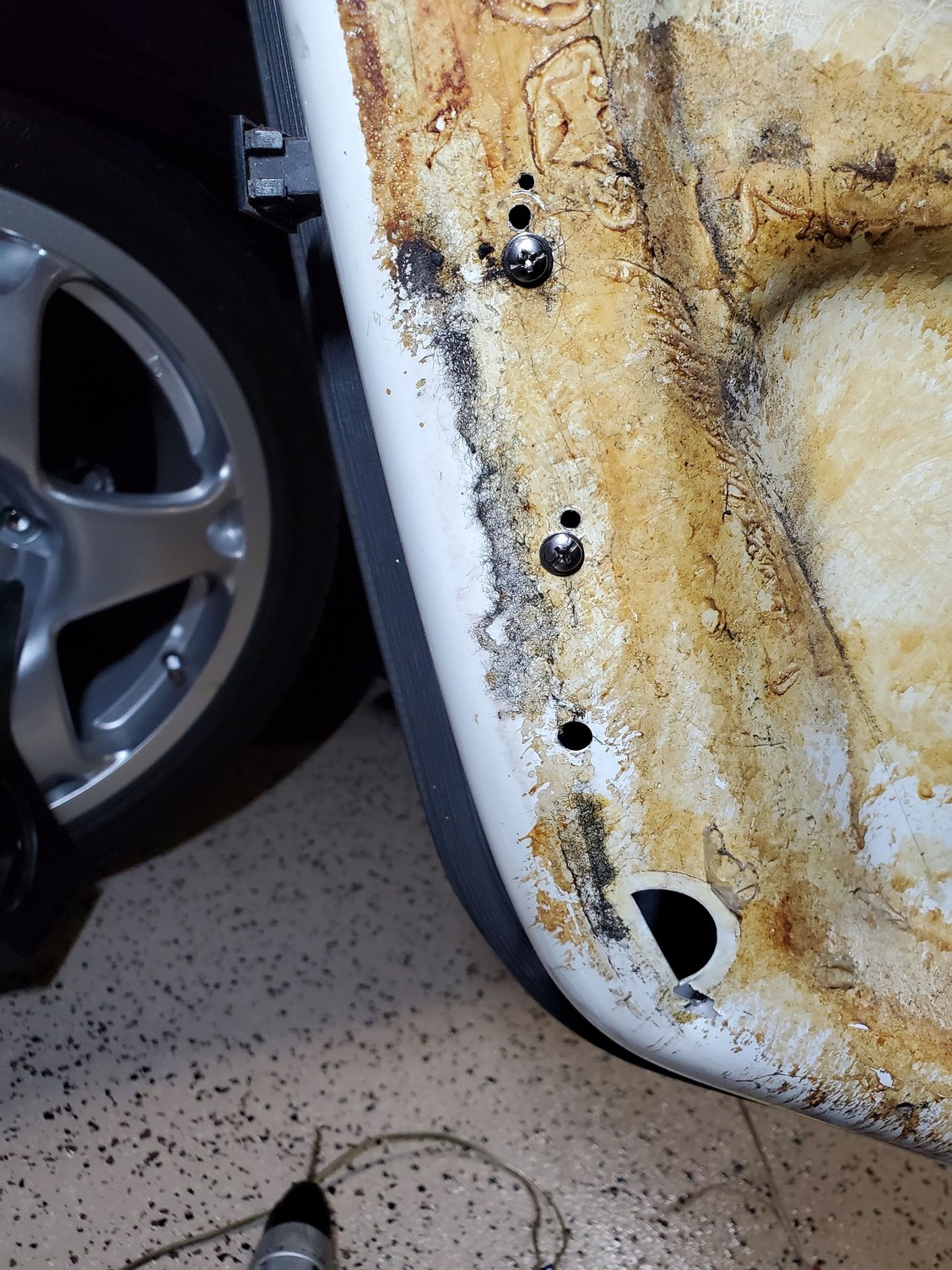
Upon taking out the old latch, it looks like it has been replaced previiusky, also using the newer electric release style, but whomever did that one just busted the front hinges off to remove the interfering release mechanism. Was a fine solution for them since the car didn't have provisions for an electric release anyway. In these pics you can see where the interfering culprits are and how they addressed it.
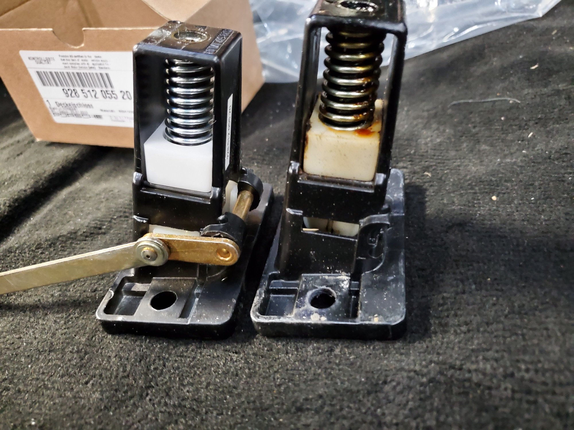
Installed the latch and put the fasteners in loosely, closed the hatch, but it wouldn't latch. I remembered that in tying to quiet it down earlier, I had adjusted the hatch hinges and also removed 2 metal shims from under the receiver assembly. Put those shims back in and tried again and with some medium force, felt. It align and catch. Gently unlocked it and secured the bolts. Tested again and perfect - a nice, tight fit that I hope addressed the hatch noise.
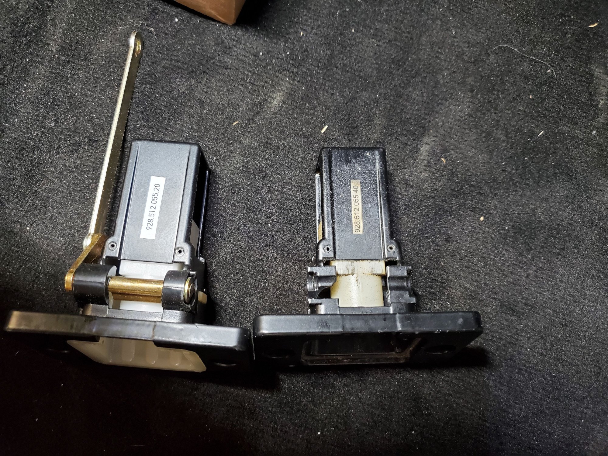
In looking at the old part that came out, it's missi. G the insert, which peopably would have also solved the noise problem, but wouldn't have let me add the electric release.
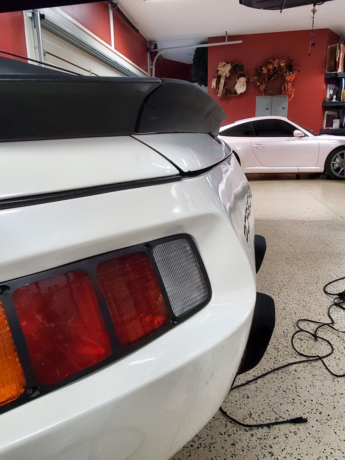
Hatch is well aligned with the bumper when closed and the release assembly moves freely on the side of the receiver.
I'll have to figure out the solenoid release contraption and how to mount that at some point as I think the OEM one is unusually complex, but haven't looked into how that mounts, what it costs, etc. Think a strong solenoid from Amazon or ebay with a cable on it that goes around a pulley that pulls the arm might work if I csn get those things well mounted and aligned some way to the arm.
That's it for this one today. Spyder is up next where I'm going to Tru and replace the ignition switch, install a new gauge foil, and blinker, cruise, wiper stalk assembly. Trying to fix my non working interior lights that blink as I turn the key to position one but not once the car is running.
Need to get the old purple window tint removed and have it redone. My tint guy likes the door panels removed for this so it's easier to tuck the tint under the window seal, so I took apart both doors tonight and while they were apart started looking into the installation of the electric lock kit with remote key fobs I bought. In this car the passenger side motor worked, but the driver's side did not and the car liked to automatically relock itself at random times. This is the same lock kit that has a remote trunk release and why I installed the later hatch catch with release arm in the previous post.
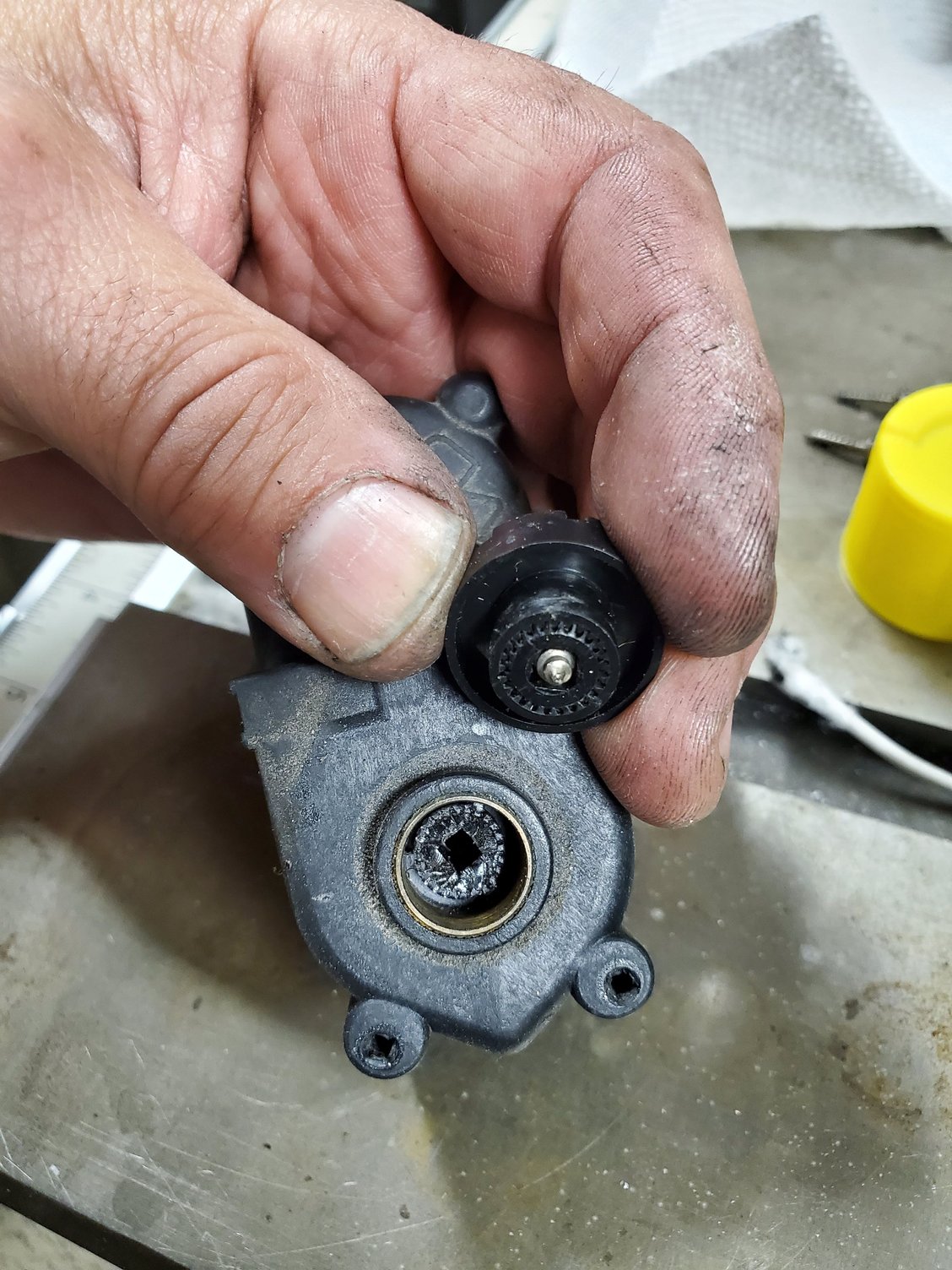
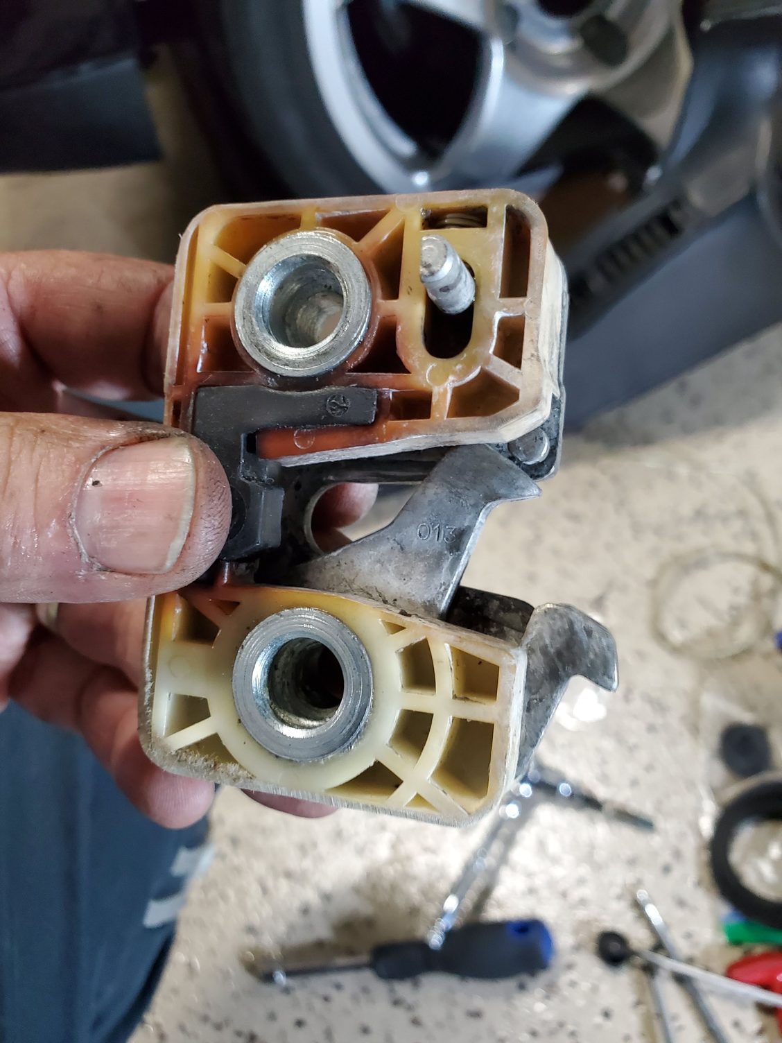
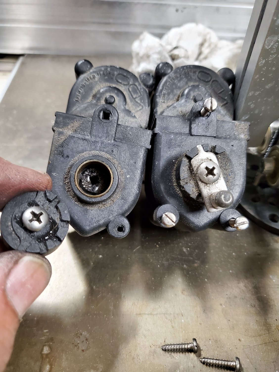
Since the driver's side was broken, I started there. Initially took thing apart to remove the electric actuator to see what might be wrong with it. Not only didn't it move with current applied to it, but also has a broken shaft that looks like maybe a repair was attempted by a PO with a screw through the shaft.
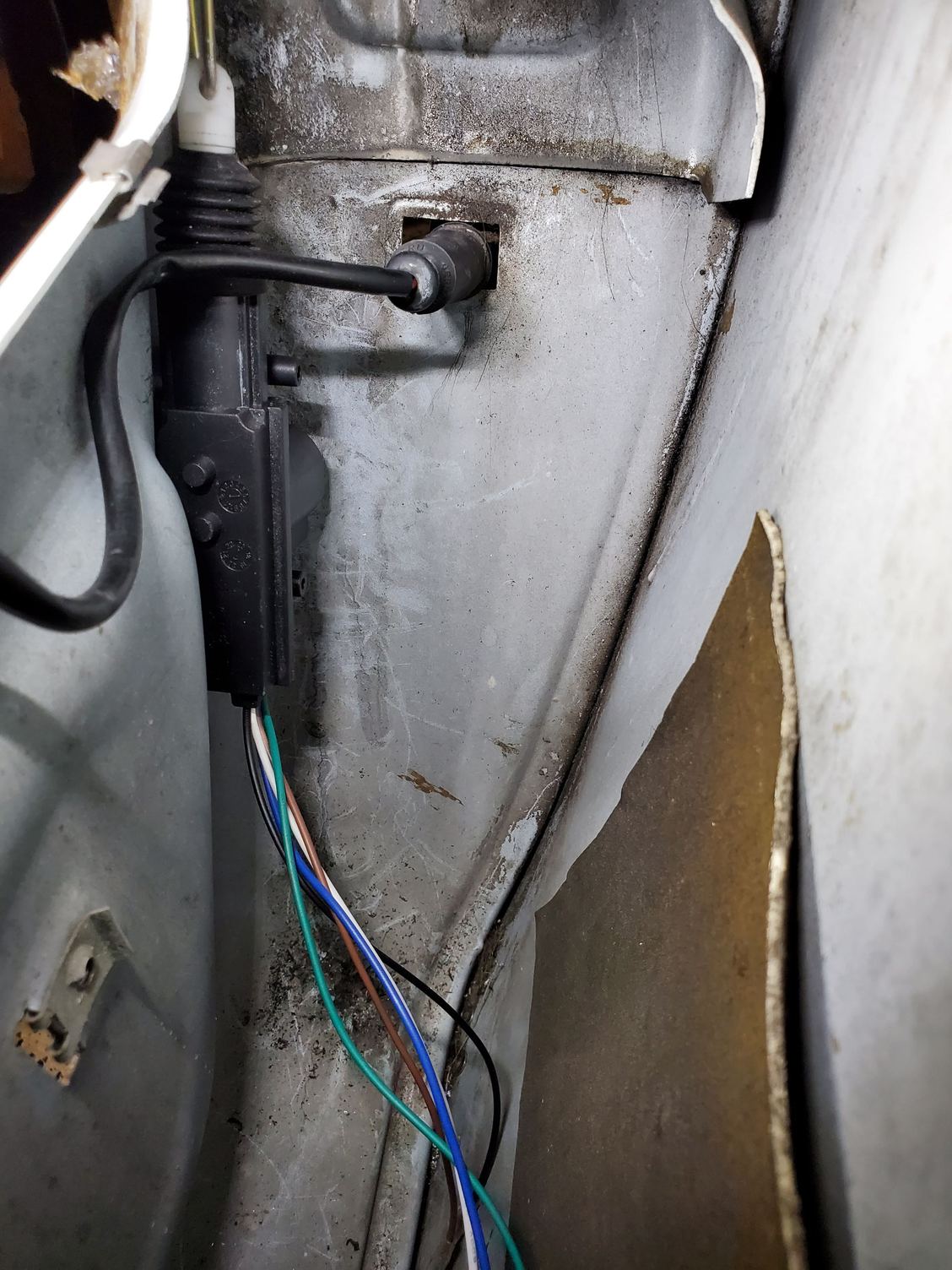
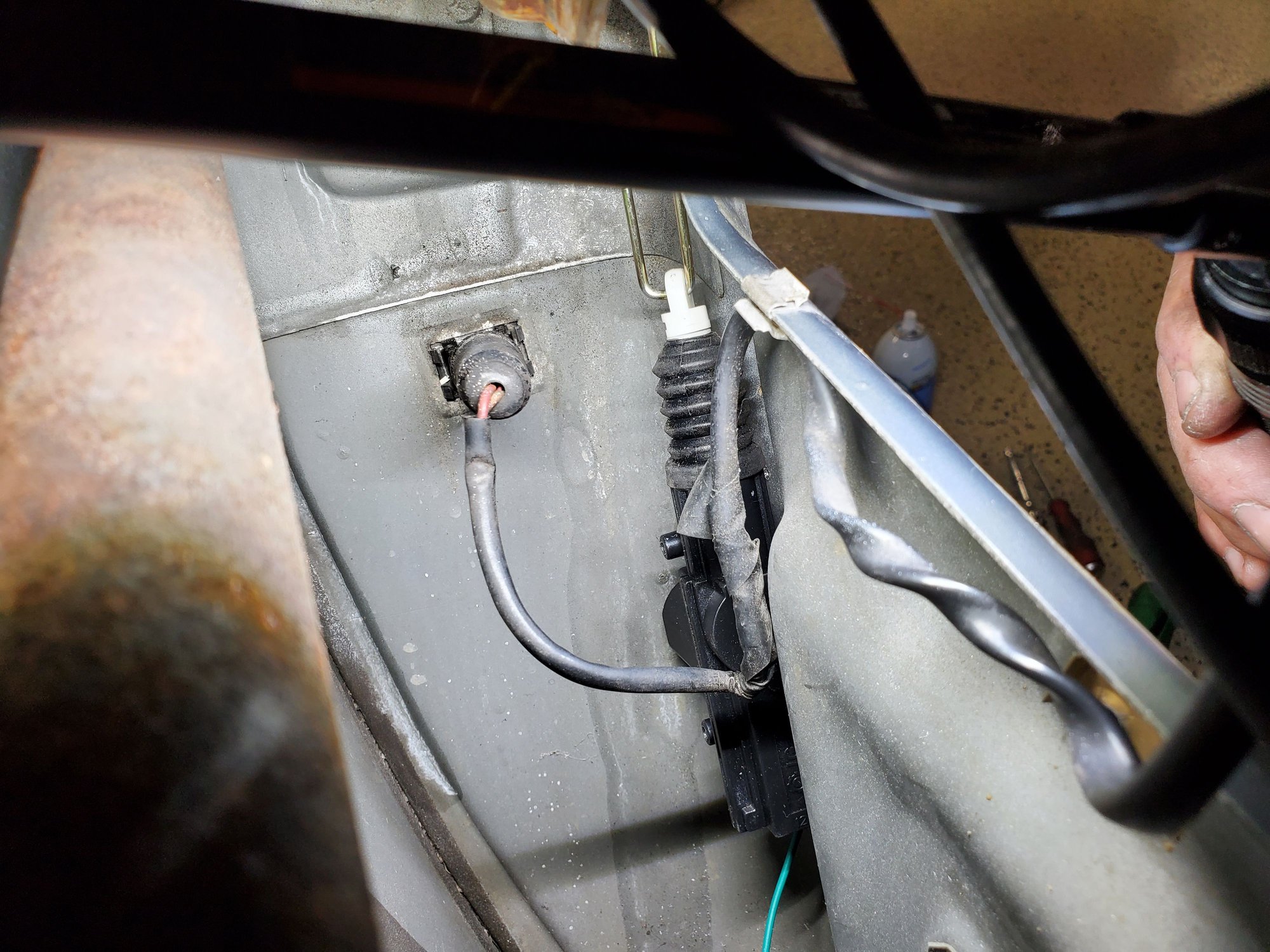
I though about purchasing a used actuator, but since my lock kit came with 4, figured I'd use them as they're the same type I have in the Spyder. Spent about an hour trying to figure out where to mount the actuator so it would push and pull in the correct plane for the locking cam. Tried up top where the old one was, but that wouldn't work so went for down along the inside edge of the door with the actuator rods that come in the kit. Once I figured that out, it still took a little trial and error to get the actuator stroke right so it would both lock and unlock the door, but the drivers side works now when applying 12v and ground to the different wires.
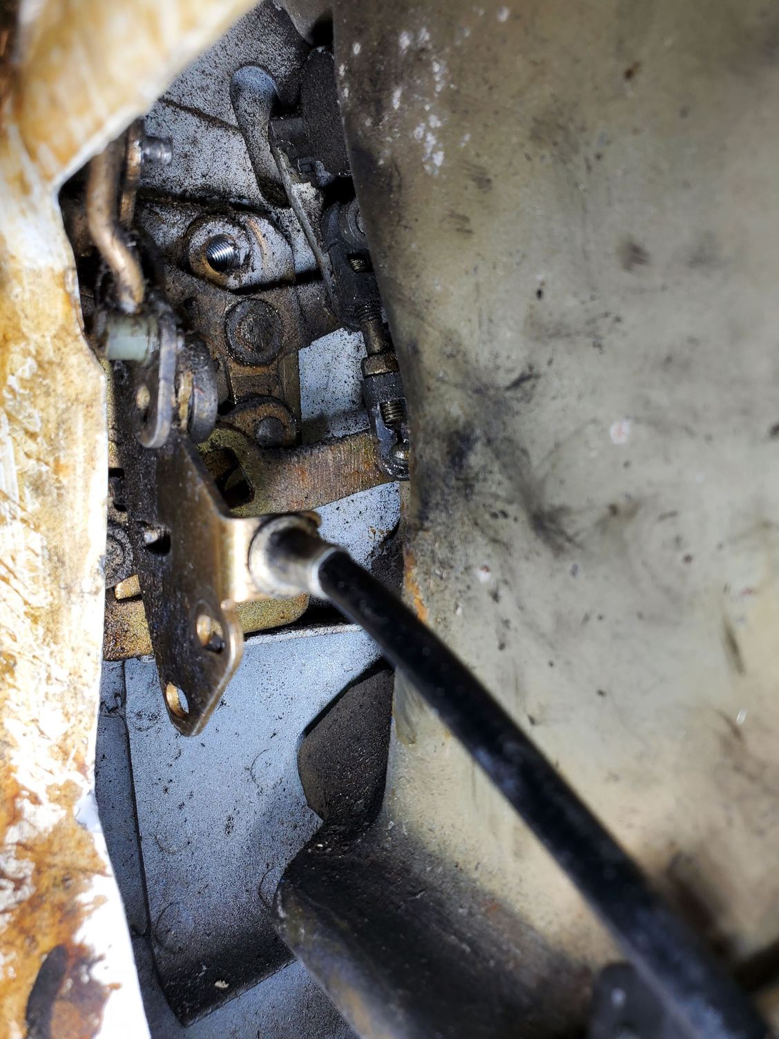
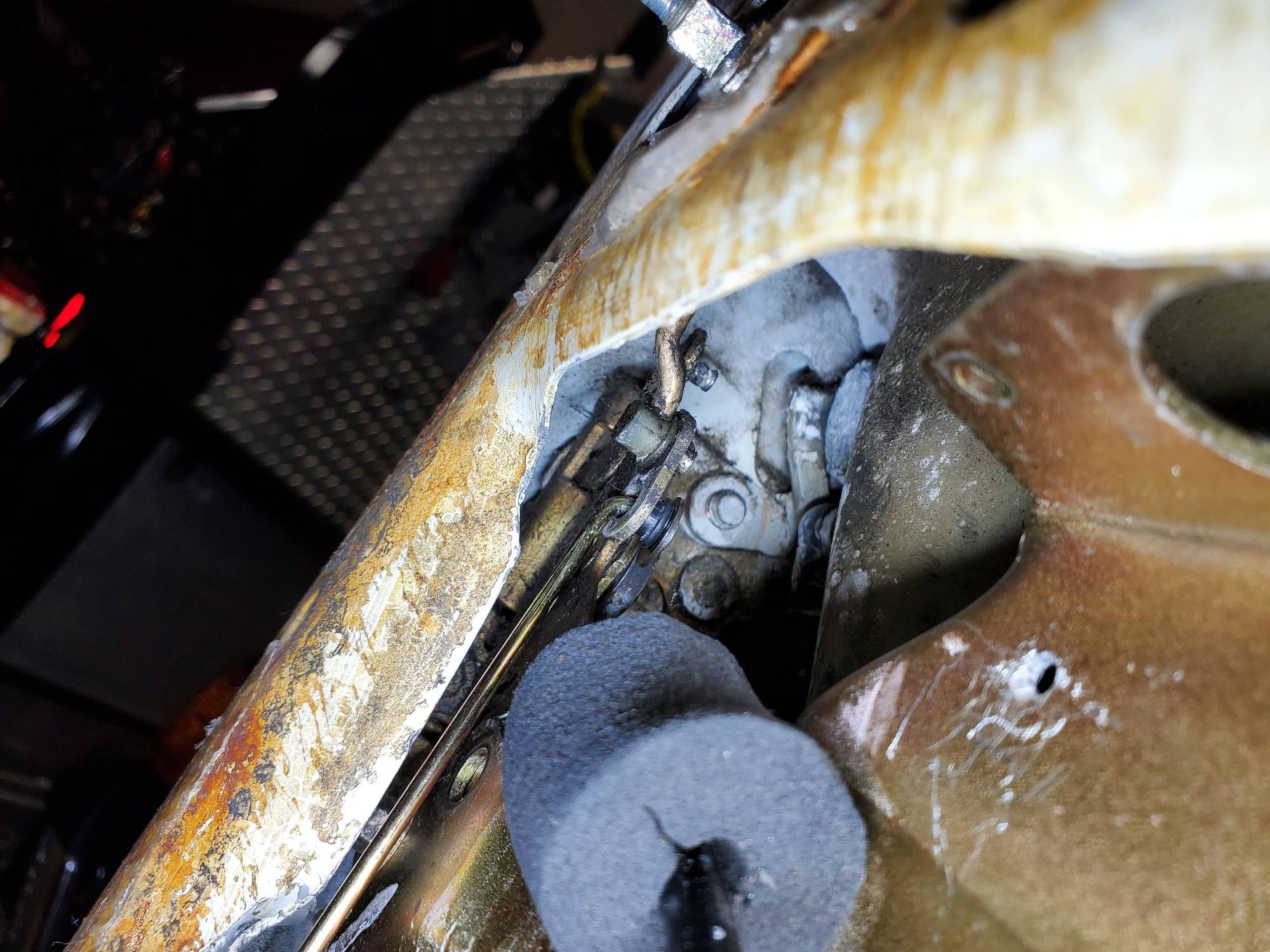
Shot of inside the latch mechanism. I am using the cam hole at the bottom for the actuator rod. Also cleaned out all the gunked up grease in the door latch assembly and relubricated it with Dry Teflon spray so it won't attract dirt anymore. Works super smooth now and the door closes much better. Inside Driver's door with linear actuator installed As I mentioned, it takes a little trial and error to get the stroke right. I had it too high initially and it would unlock the door great, but wouldn't lock it. Works perfectly now. Here you can see the arm from the linear actuator that goes through the locking cam. I used a small hole rubber grommet to hold the arm tight and then a washer that just barely fit over the end as a retainer. The rubber grommet probably would have held it without the washer, but though it might wear. Had to replace one of the door plate screws with a lower profile one that the locking arm could pass by and "adjusted" the metal of the door in that area a little bit too.
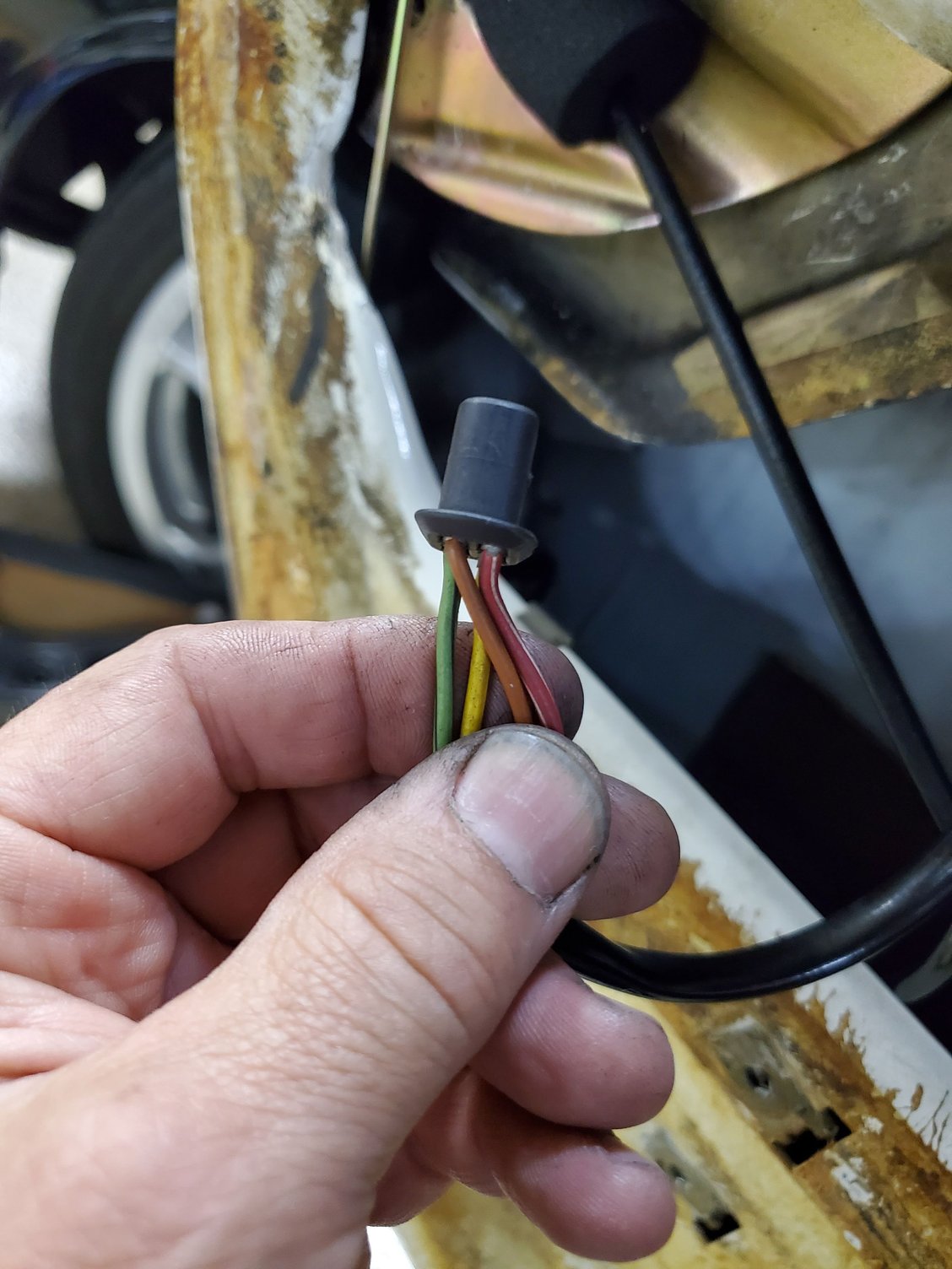
For the passenger side, where the original motor still works I'm thinking about just connecting the lock controller to the two two wires I need to reverse polarity on for open and close. Does this one work like this or is it different? Anyone know which two of the four wires actually extend and retract the actuator. I'm assuming brown and one other color. I also assume red is probably 12v Constant so the locks work all the time. I don't need that wire for this system as it's going to pulse the 12v signal from the remote and lock brain, so probably one of the other wire colors or maybe it's the green and yellow ones, or maybe I can't make the original actuator work like the new one and I'll just remove the OEM on and do the passenger side like I did the Driver's side, as I believe it's this actuator that's relocking the doors randomly.
Also discovered a wire disconnected from my mirror controller and probably why the driver's side mirror wouldn't adjust.
I'll probably take it for tint on Thursday when it's not raining so I can start putting the doors back together with the new speakers and panels I have, then I'll pull the center console and do all that work at the same time for the new stereo, new leather dash pod, etc.
On a separate topic, has anyone tried to adhere a leather dash cover to the dash with the main dash in the car. Seems like you could mask off the windshield and surrounding areas, apply spray adhesive and dry mount the new cover onto the old dash without having to remove it from the car. My new pod is leather, my used center console is leather, but my dash has some type of smooth plastic cover over it that's not cracked or anything I why I thought I might be able to just adhere a leather cover to it.
Pete dash has to come out to install a new leather cover.
That plug looks like the it goes to the door lock actuator.
NOTE a similar plug also goes into the hatch release motor
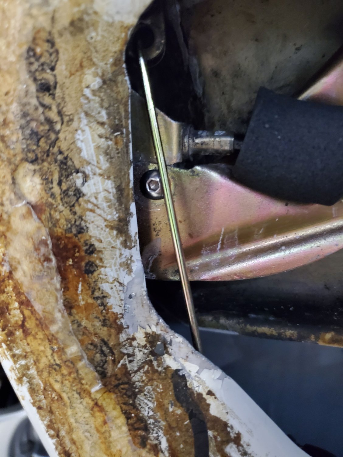
NOTE that clamp is not needed on your MC tank outlet for the clutch,
and if its over tightened then the plastic can be deformed.
That silicone line is a press fit and the line will not see any pressure.
I hope you used DC111 on the grommet bores before you installed them into the MC,
this will prevent the bores from corroding,
every time the car is wet water will run down the tank onto your inlets.
Pete dash has to come out to install a new leather cover.
That plug looks like the it goes to the door lock actuator. It does, Is the top section with the gear broken off from the guts? Not that it matters as the electrics in it arent' any good either so I replaced it with the linear style and will likely do the same on the other door.
NOTE a similar plug also goes into the hatch release motor. Since you mentioned this, if I do the Passenger door the same way I did the Driver's door, I may be able to use my working passenger door actuator as a hatch pop. It won't be wired the normal way. Do you know which two wires cycle the motor and why there are 4 wires on the normal OEM actuators?
NOTE that clamp is not needed on your MC tank outlet for the clutch, and if its over tightened then the plastic can be deformed. That silicone line is a press fit and the line will not see any pressure. I left it fairly loose since it's clamping plastic, but realize it's not under pressure.
I hope you used DC111 on the grommet bores before you installed them into the MC, this will prevent the bores from corroding, Of course !
every time the car is wet water will run down the tank onto your inlets.
Stan, thanks for following along and for the input. Comments are after your statements.
Great work Pete. I am copying this for my 79 euro, once I remove the old vacuum actuators!
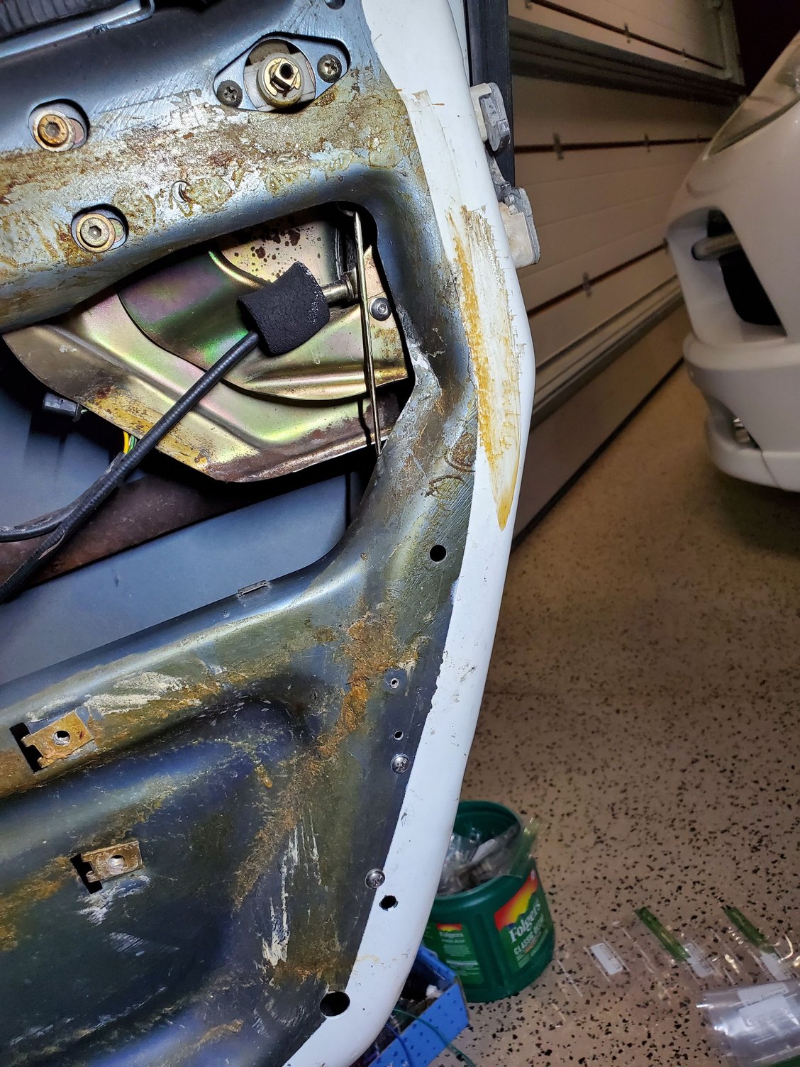
Thanks Ron. I took a look at the rear hatch pop for a bit last night too and haven't really come up with a good solution for how to make that work yet. I'll probably look at a couple cars at Sharks that have it to see how Porsche mounted and oriented the motor drive.
It looks like the gold arm on the hatch catch has to be pulled down and that knocks the catch on the upper hatch free so it can pop up, but there's not a good way or orientation to grab that gold arm. My current thought is a pull solenoid where I cut a slot into the top cylinder, drill a hole through the side and then mount that to the arm, but then I still need a solid way to mount that solenoid behind the tool cover. Piggybacking onto the rear wiper motor mount with a custom bracket might be one way. We'll see.


 04-20-2021, 12:38 PM