When you click on links to various merchants on this site and make a purchase, this can result in this site earning a commission. Affiliate programs and affiliations include, but are not limited to, the eBay Partner Network.
Don't expect much viable data from knock sensors on early 928 engines.
Porsche, in their infinite wisdom, has used pistons with "offset" piston pins, virtually forever. (The piston pin isn't centered in the middle of the piston, but is moved towards one wall (skirt) of the piston.) 356's, 911's, 914's, 924's, 944's, and 928's (up to the introduction of knock sensors in 1987) were all this way. The "rub" is that on all the engines with pistons on different sides (everything except inline 4 cylinders), the pistons have an up and down (different size valve reliefs for intake and exhaust. This means that the offset of the piston, in relationship to the crankshafts is different from side to side of the engine. One side of the engine ends up with the offset such that "piston slap" is reduced. The other side has the offset up in the incorrect direction and the piston slap is greatly increased (But, interestingly enough, makes slightly more power.)
Not their "brightest" engineering moment. And, frankly, a bit "thickheaded" to keep making this mistake over and over again....model after model. Especially "slow" for a company that "hangs their hat" on their superior engineering capability.
When they developed the knock sensor system, the piston slap from the pistons that were backwards in the engine, fooled the knock sensors to the point where they were useless. Porsche was forced to make pistons with symmetrical valve reliefs (in 1987 and later), so that the pistons could be installed with the valve reliefs facing the correct direction, eliminating piston slap.
(^^^^^^This concept can be difficult for "normal people" to grasp. Trust me, it's a big deal.)
I don't know anything about engine design so this might be a stupid question but what about the Cayenne engine? I vaguely recall that they have a similar setup... Along with a tendency to kill themselves with bore scoring and a lot of piston slap.
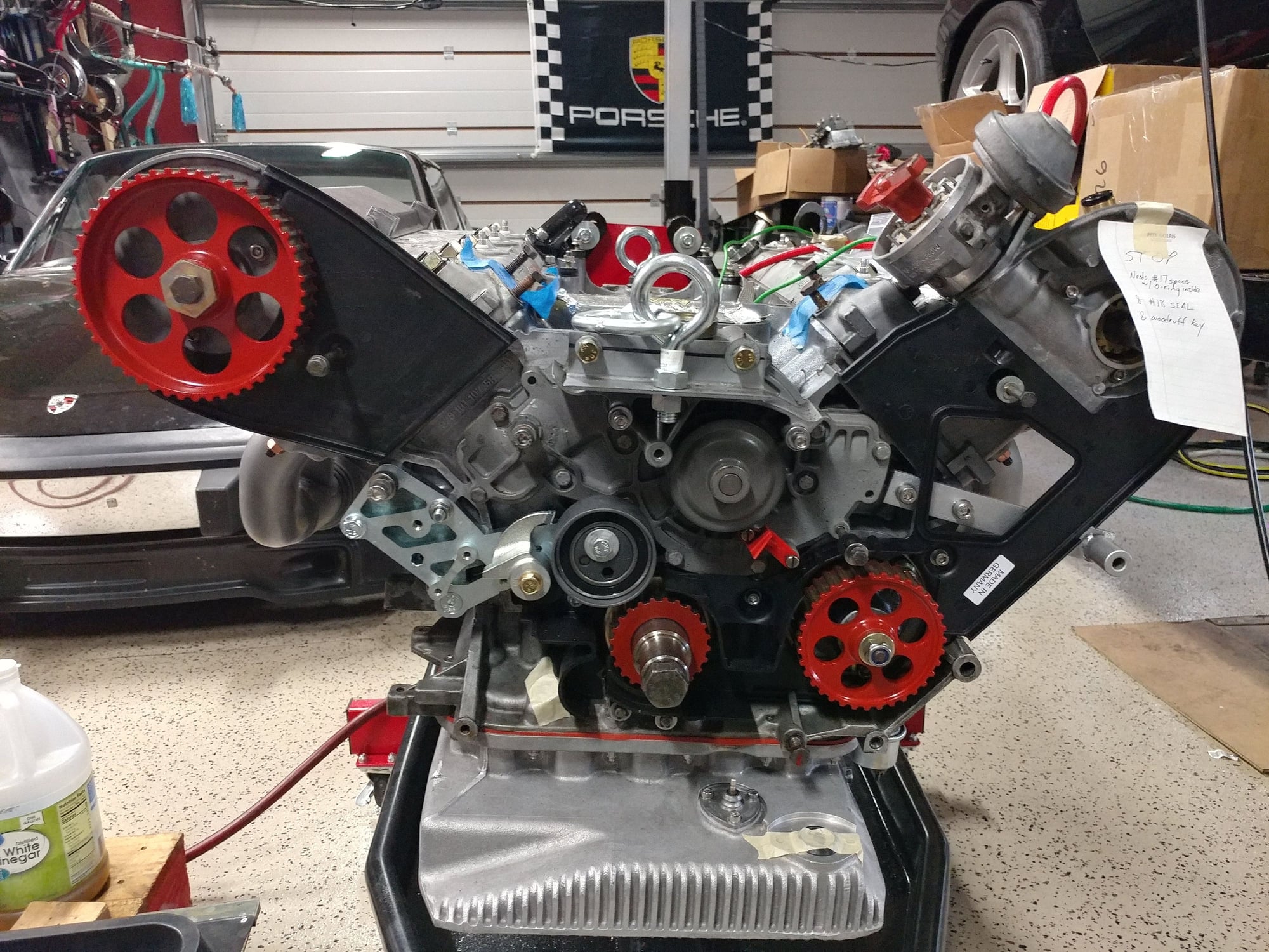
Camshaft seals from Roger arrived today so Bank 1-4 is now put together. Waiting on the cam spacer for the 5-8 side and then I'll assemble that one too. New (used) distributor with both advance and retard ports installed too with a new sealing ring. It will get a new rotor and cap too.
Waiting on a couple more things that arrive tomorrow & Friday and then I can really start making some reassembly progress - going to be a busy weekend.
Don't expect much viable data from knock sensors on early 928 engines.
Porsche, in their infinite wisdom, has used pistons with "offset" piston pins, virtually forever. (The piston pin isn't centered in the middle of the piston, but is moved towards one wall (skirt) of the piston.) 356's, 911's, 914's, 924's, 944's, and 928's (up to the introduction of knock sensors in 1987) were all this way. The "rub" is that on all the engines with pistons on different sides (everything except inline 4 cylinders), the pistons have an up and down (different size valve reliefs for intake and exhaust. This means that the offset of the piston, in relationship to the crankshafts is different from side to side of the engine. One side of the engine ends up with the offset such that "piston slap" is reduced. The other side has the offset up in the incorrect direction and the piston slap is greatly increased (But, interestingly enough, makes slightly more power.)
Not their "brightest" engineering moment. And, frankly, a bit "thickheaded" to keep making this mistake over and over again....model after model. Especially "slow" for a company that "hangs their hat" on their superior engineering capability.
When they developed the knock sensor system, the piston slap from the pistons that were backwards in the engine, fooled the knock sensors to the point where they were useless. Porsche was forced to make pistons with symmetrical valve reliefs (in 1987 and later), so that the pistons could be installed with the valve reliefs facing the correct direction, eliminating piston slap.
(^^^^^^This concept can be difficult for "normal people" to grasp. Trust me, it's a big deal.)
Interesting, I guess we'll see if I can pick up anything or if the noisy side calibrates the sensor to a baseline where it doesn't pick up knock on the quiet side very well.
I understand what you're saying about the offset wrist pin location in the piston, as the 997 M97 motors are the same way, and I think maybe the Cayennes too. In some of these engines, they think it might be a contributor to bore scoring as the piston "rocks" during it's travel in the cylinder due to the offset pin position on one side.
My understanding is that Cayenne bore scoring happen on cold starts in very cold environments. My guess is that the piston fit is too tight and that as the piston warms up very much faster than the block it is briefly too big. Maybe too simple minded though.
Kevin Wilson (aka Jetson...) bought a Cayenne while at the last Frenzy. Borescope revealed some scoring and intermittent check engine light. Came with a complete replacement engine. Soon after he bought it threw a code - a timing chain jumped. Local Porsche dealership offered to empty Kevin's wallet. Instead. Kevin shipped the Cayenne back to VA to be repaired, bought a used head to harvest the broken tensioner and since repaired is running great - in fact he drove it to Missouri and back with no issues. My guess is the earlier codes were due to the failing tensioner. The replacement engine is sitting in a storage unit outside Atlanta.
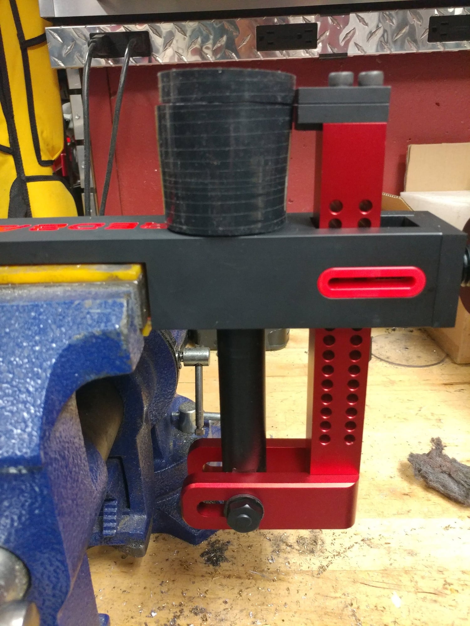
Tonight I used a new tool that's designed to make the cutting of silicone hoses, fast, easy, and most importantly, precise.
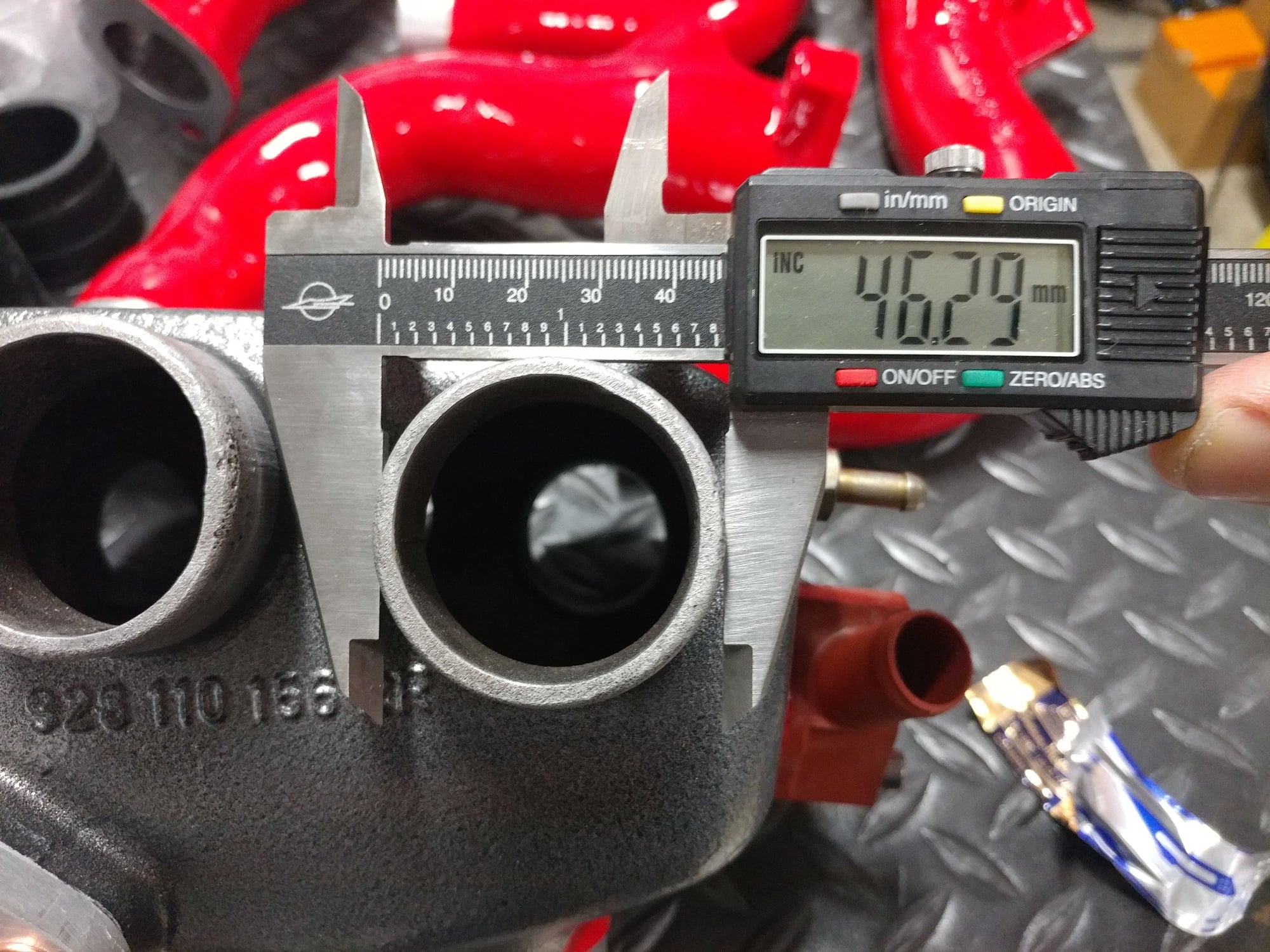
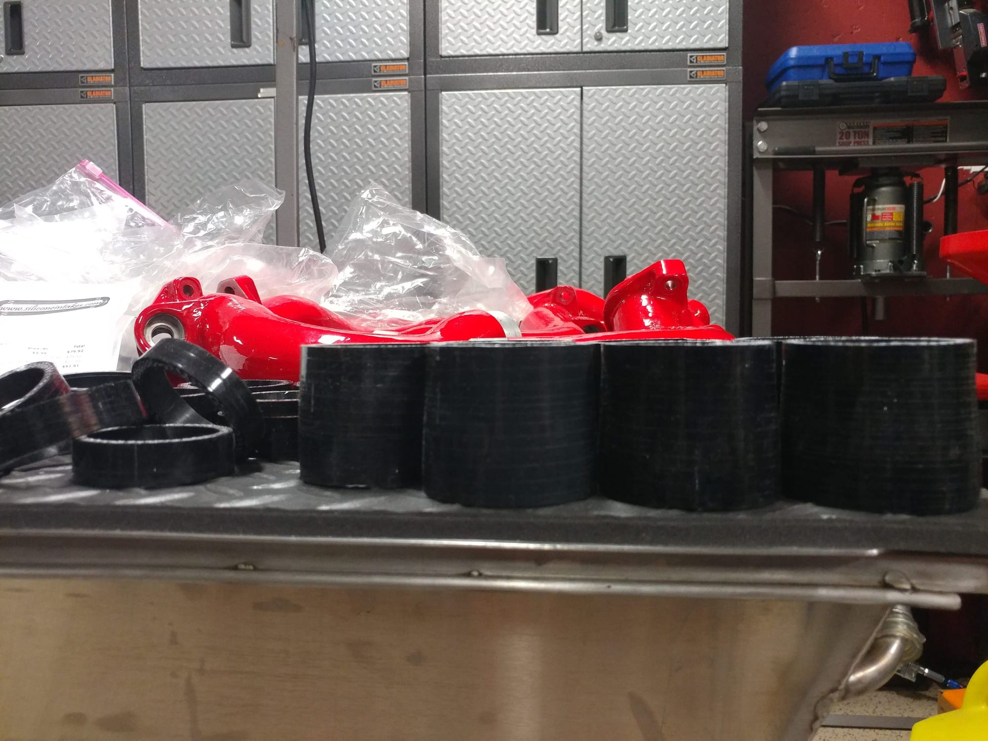
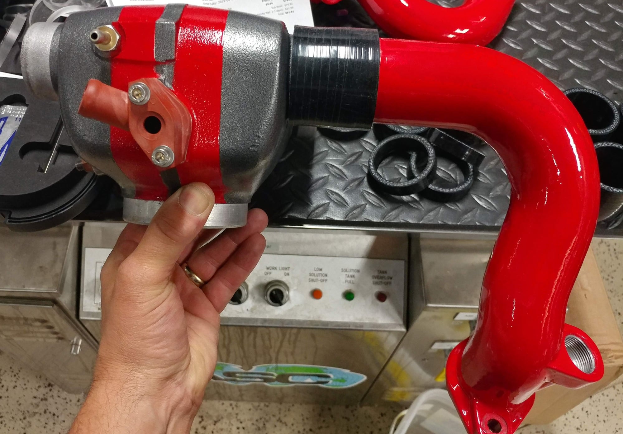
On my car I'm running Euro intake legs and a non-Euro body, primarily because I found these beautiful red powdercoated intake legs a few years ago that looked at lot better than the ones I had painted. The challenge with this setup is that the diameter of the leg ends is larger than the fittings where they connect on the manifold.
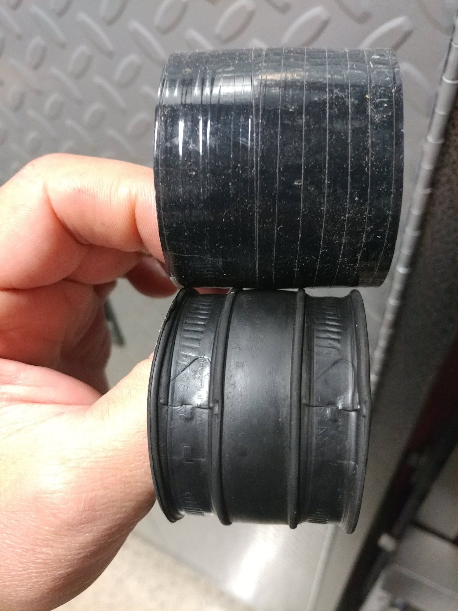
The non-Euro version of the couplers fit the manifold well, but are really tight on the legs, and the Euro versions fit the legs perfectly, but are too loose on the manifold. Figuring tighter is better than looser, I had been using the non-Euro versions and just stretching them over the Euro leg ends, but a couple of them had started to tear at the edges, and I assume the intake air going from a larger opening to a smaller one, without any sort of transition, probably created a little turbulence, though probably not enough to matter since the car ran great.
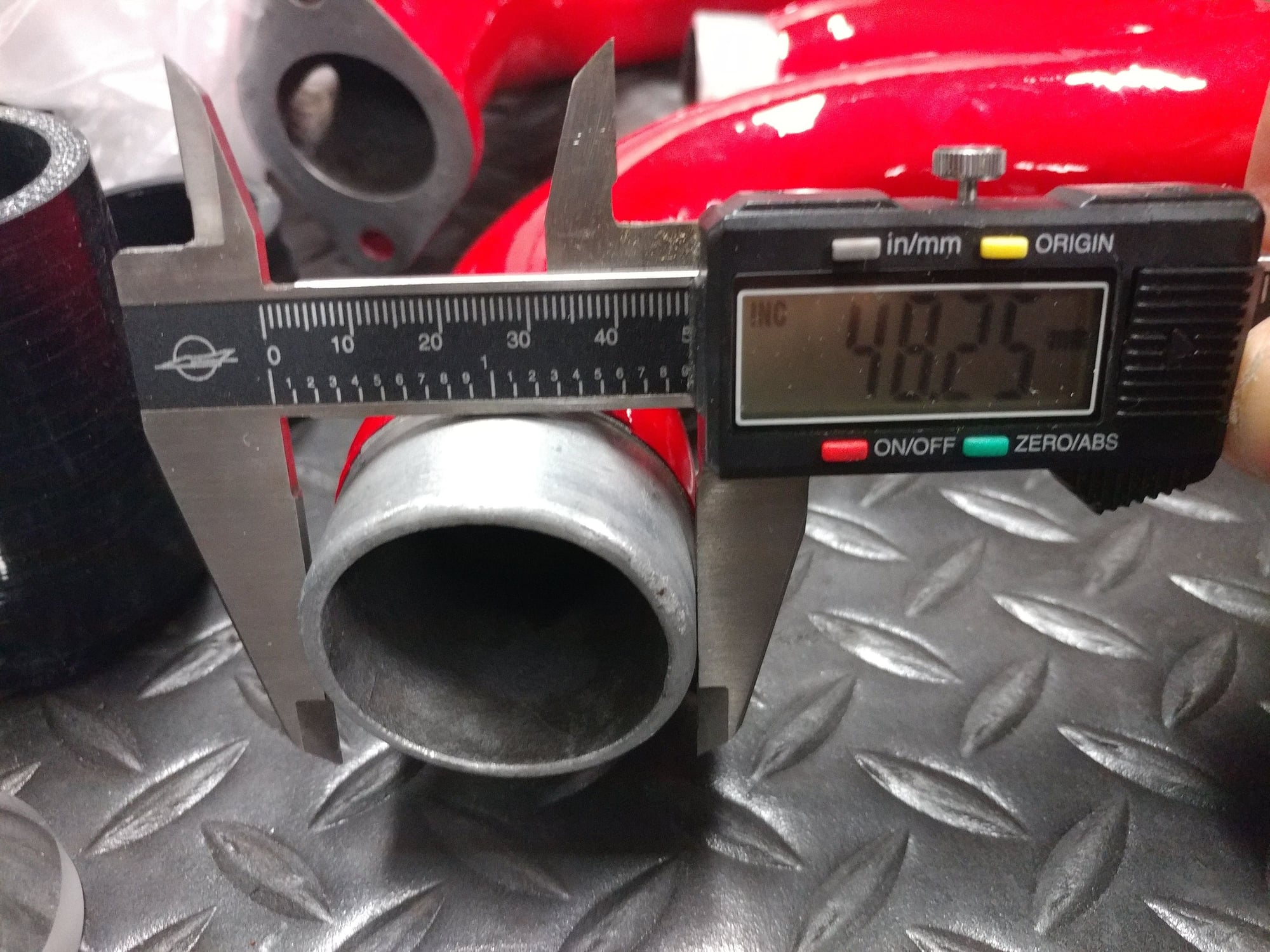
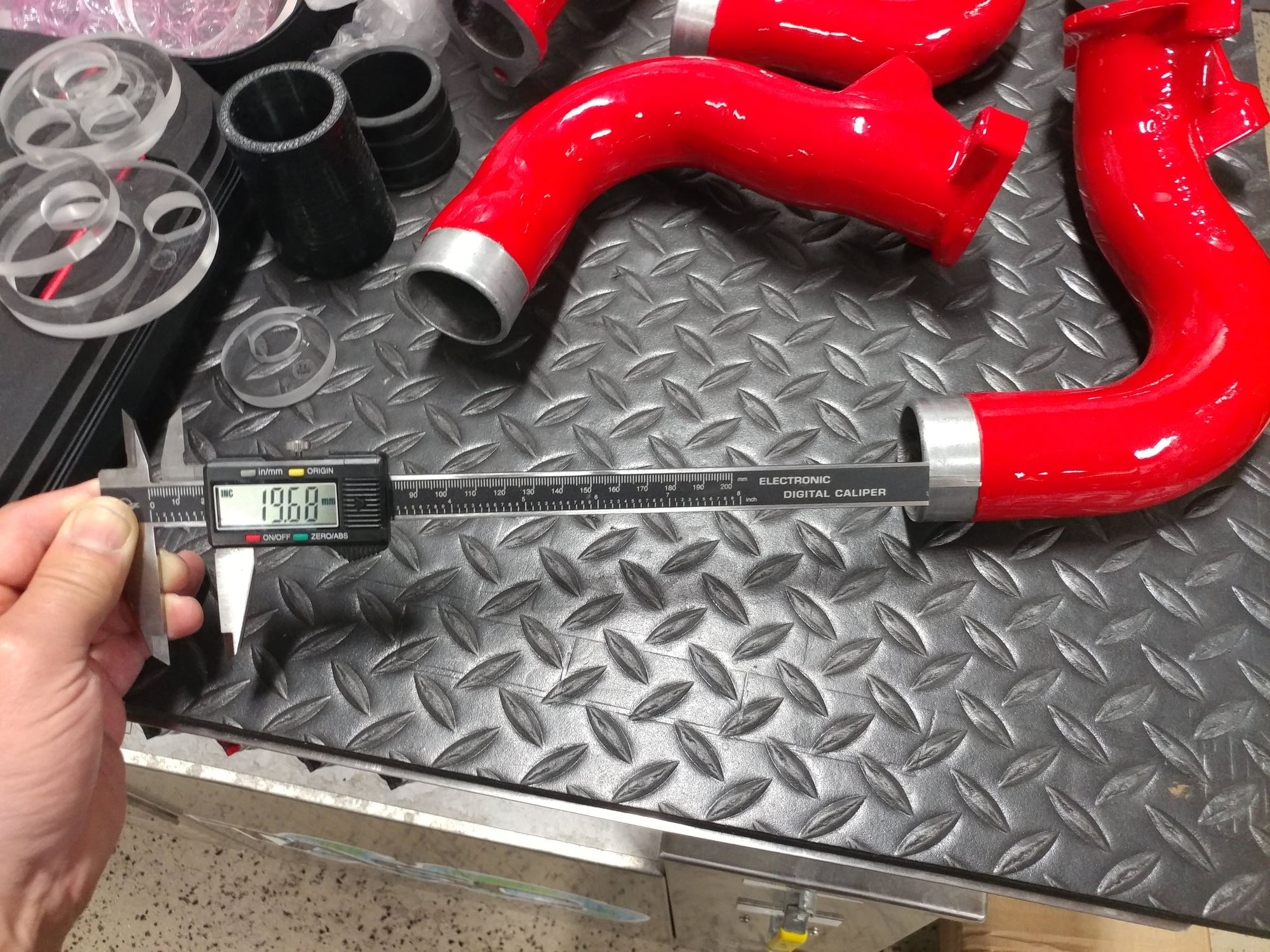
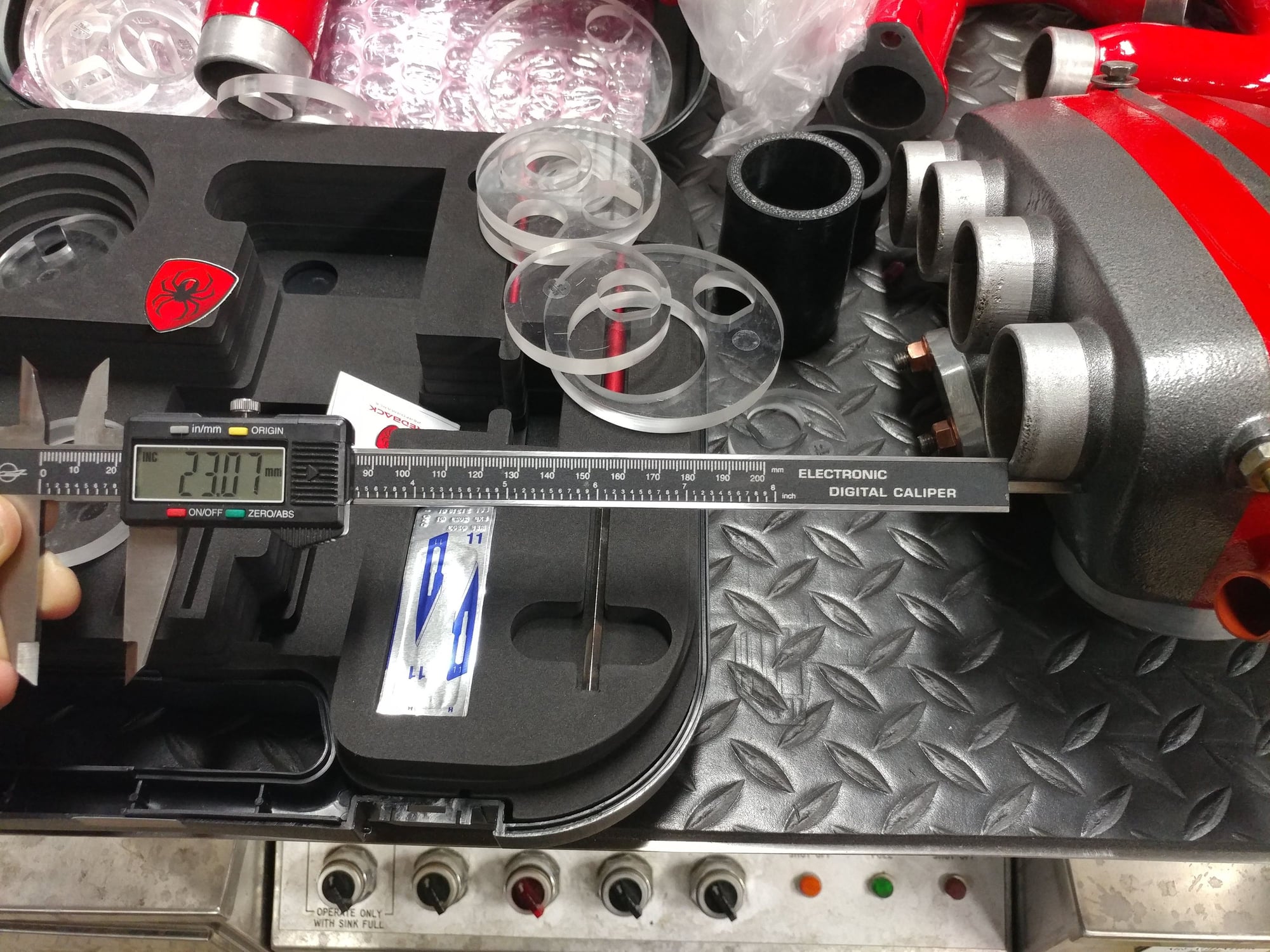
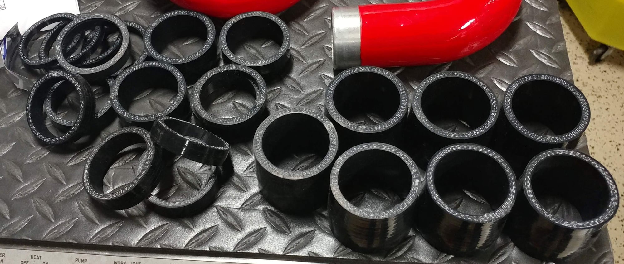
But while I was doing all of this, I decided it would be great if I could find a source for a coupler that was the proper size on each end with a smooth transition between them, and in doing some online research, came across www.siliconeintakes.com that has all types of high-quality, multi-ply, silicone hoses available. They make a silicone reducer that goes from 1.875" (47.625mm) on one side to 1.75"(44.45mm) on the other, which is just about perfect, as both ends are just a little smaller than the pieces they slide onto, so I ordered 8.
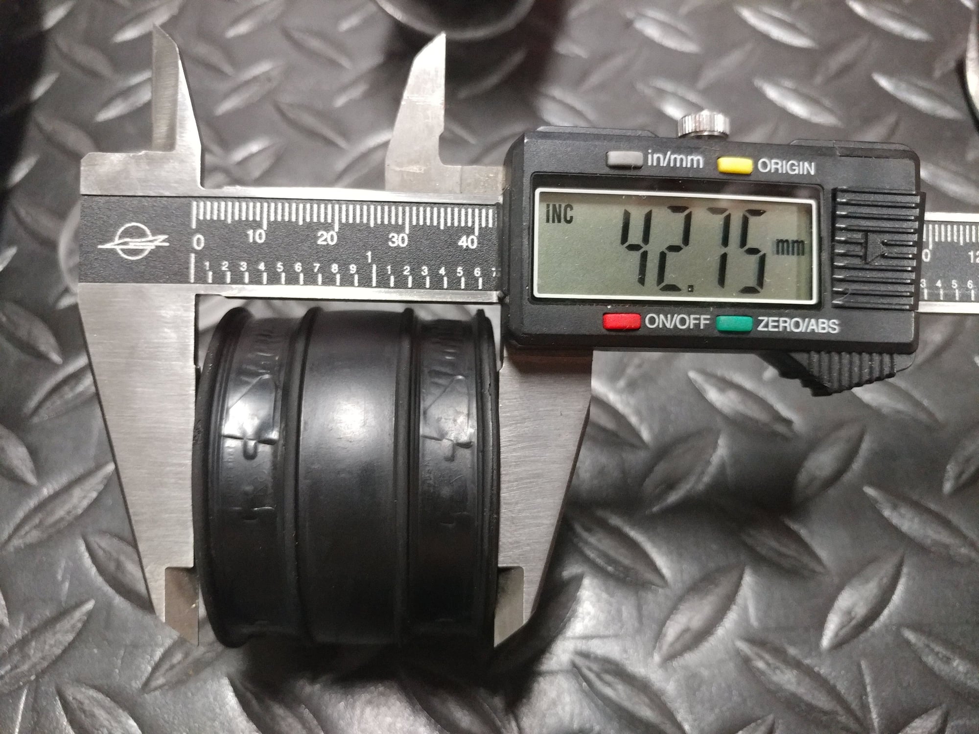
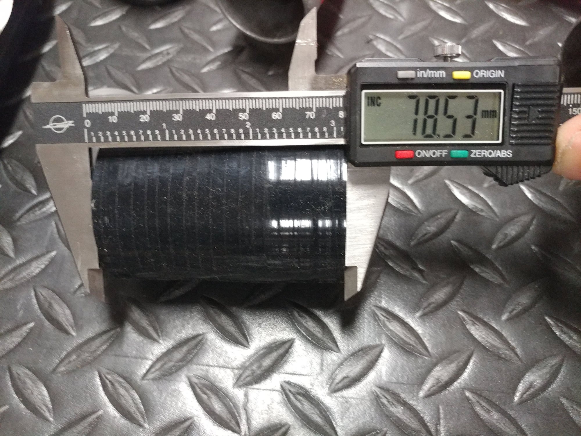
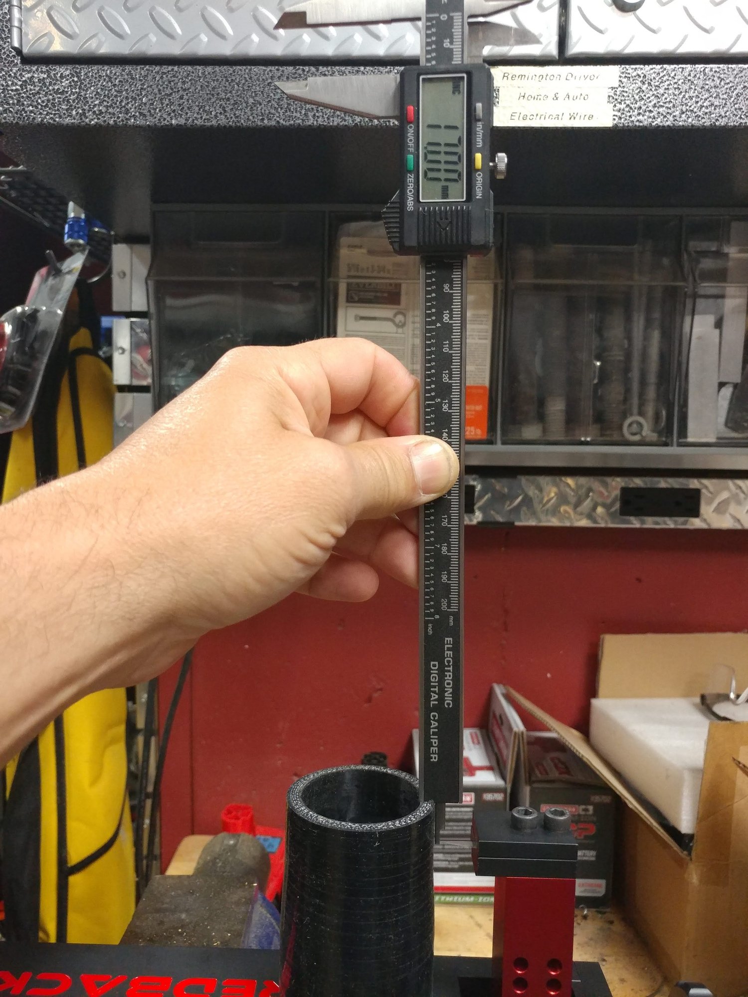
The next challenge with them is that they're about 3" (78.53mm) in length, and the OEM couplers are only 42.75mm, so I would need to trim them down to a proper length, as you don't want them to extend beyond the smooth flange on the leg, and they can't extend on the manifold as they hit the body sides.
Having worked with silicone hose in the past (my custom cold air intake project), I was kind of dreading the trimming down process as I've tried a number of different techniques (band saw with a fine tooth blade which can get a little exciting if the band binds a little in the soft silicone, a razor knife cutting against a PVC pipe edge as a guide, etc, but none of them work all that well, and you end up with rough or wavy edges or have to try and recut a small strip to try and get it smoother, which usually just makes it worse.
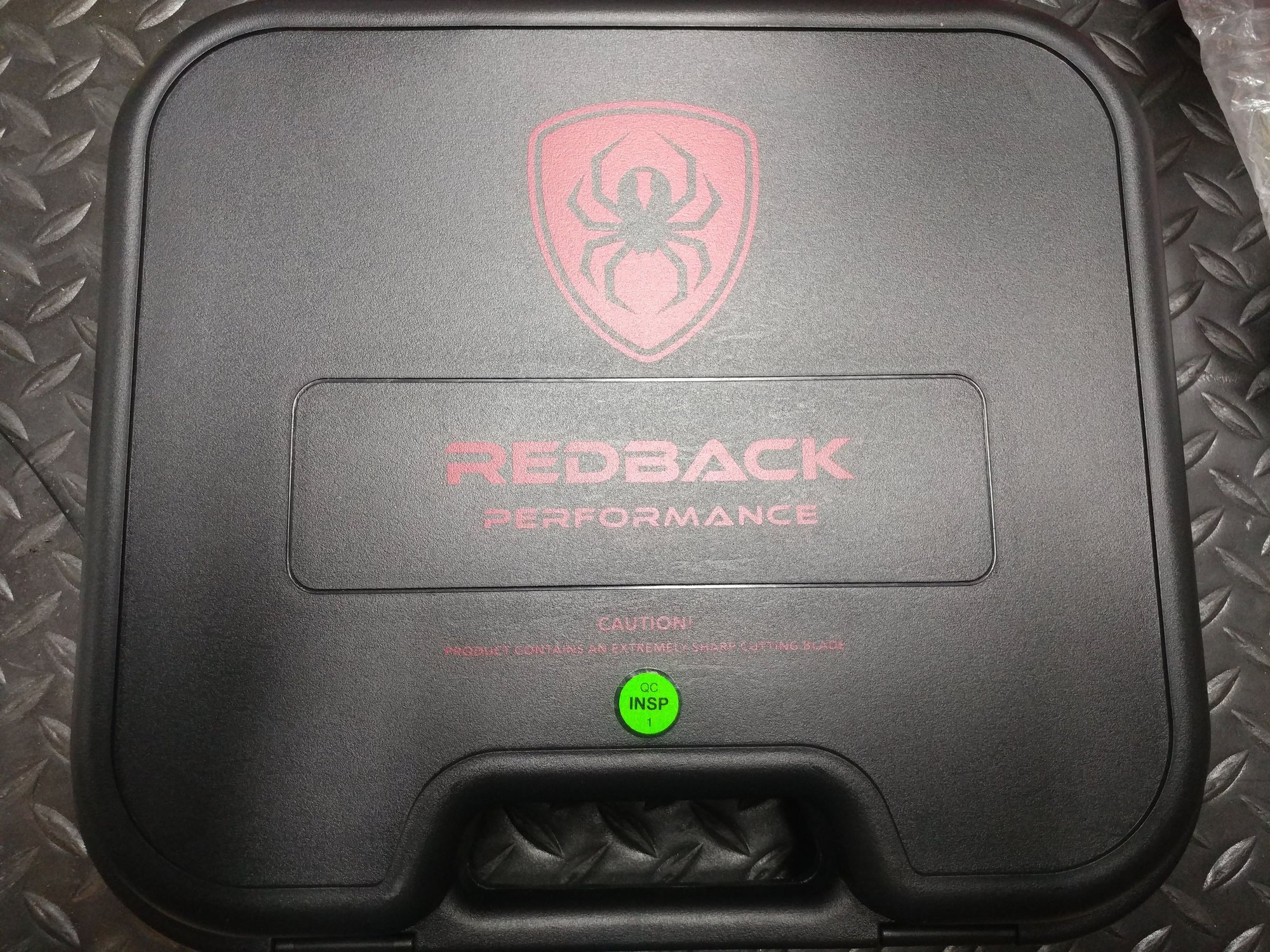
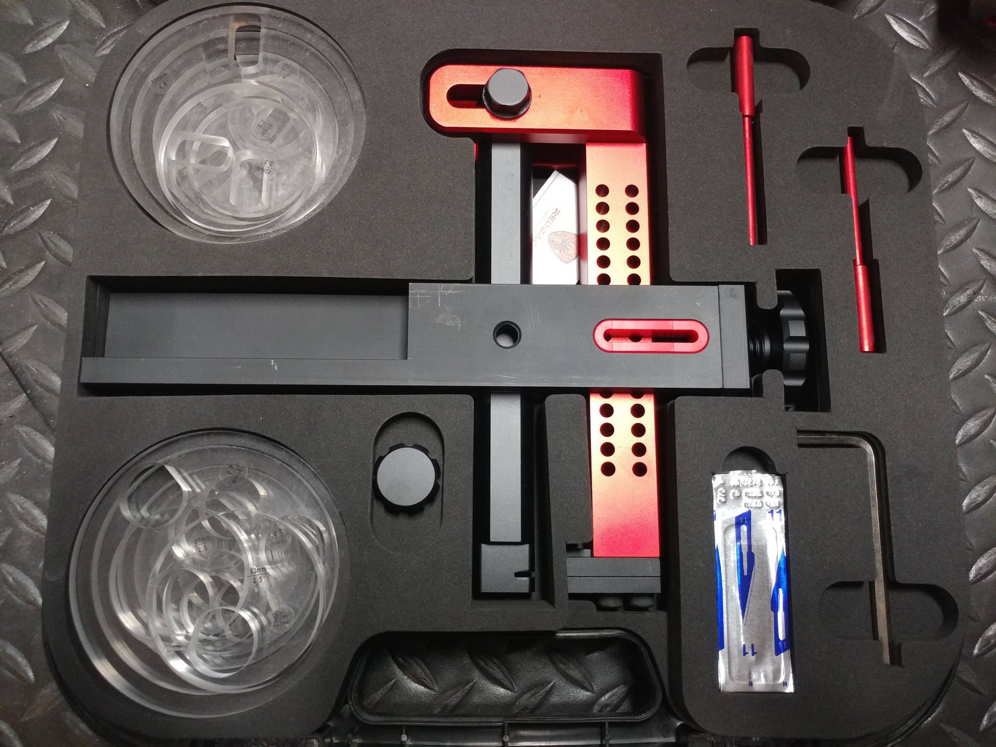
Enter the Redback - made by an Australian company, it's an awesome tool for precision cutting silicone hoses up to 4" in diameter. It clamps in your vice, gives you various sized guide discs, a precision arm that's adjustable for the length of hose you want to cut, and uses a razor knife blade that you engage with the hose, then rotate the hose to make the cut. I can't tell you what a nice design and quality piece this is with anodized aluminum, a case that neatly organizes the two sets of discs (a top set and bottom set to support the hose at both ends), the guide pins, the assembly itself, etc - it's just first rate.
....but most importantly, it works. and works well !
I had to cut both sides of each reducer to keep the transition section centered between the two ends and checking the fitment, I ended up trimming more from the smaller end and less from the larger end, as they fit together better that way. When doing the measuring, I wanted the finished product to be just a little bit longer than the OEM ones, but just 1-2mm or so. The leg flange is 19.68mm and the manifold flange is 23.07mm so together, that's 42.75mm and the OEM coupler length is exactly 42.75mm, but the two parts have a slight gap between them when installed. Making the couplers just a little longer would have them fully cover the leg and manifold flanges, but not exceed past the lip on the leg flange, and go all the way to the side of the manifold body. Since the silicone hose is slipperier than the OEM rubber pieces, I wanted to do this to help keep them from sliding in either direction due to the high pressure air of the forced induction system.
What I ended up with is 8 perfectly sized couplers, with smooth and straight cuts - no way I would have been able to achieve this type of consistency and quality without this tool.
Don't worry, there are 8 of them - one was still on the cutter in this picture
Pegasus Racing Supplies is the one that sells Redback tool (I discovered them when looking for a metal canister oil filter cutting tool to inspect my filter media for debris during oil changes). Is it kind of expensive for a hose cutter - yup, but the quality is worth the price, and if you do this type of work on your cars, you'll look forward to the next project where you're cutting hoses to fit, instead of dreading that part of it.
Sweet! Lots of great details coming from your documentation.
Thank you for taking the time to post all of this.
I'd rather be driving it than working on it, but since I have to be working on it, figured I might as well post up what I'm doing in case it helps someone else with a question down the road or lets one of the experts see a critical mistake I've made that I can correct before going further.
Once the new 5-8 cam spacer arrives today (both my other ones were grooved), I'll be putting the pulley onto that side and finishing the timing and porken tensioner install.
From a relationship perspective, am I correct in my understanding that this is how things should be put together so that simultaneously:
The Crankshaft is set at TDC - red plastic arrow pointing to the line between the T|C on the harmonic balancer
1-4 cam pulley aligned with it's arrow mark
5-8 cam pulley aligned with it's arrow mark
Distributor set with rotor pointing to it's thin alignment mark, which is also the position for cylinder 1
Rotating the motor around a couple times it should always come back to this state, correct?
When I try to manually rotate the 1-4 cam pulley to align the mark on the pulley with the mark on the end plate, it feels like I'm compressing a valve spring and it does not want to stay there. I know once the belt is on and under tension that it will stay there, but is that phenomenon correct before the the belt is installed. Both the crank and the 5-8 pulley will align with their marks without that same resistance phenomenon.
Also I've read that the 1-4 pulley mark might not exactly align with the mark on the cam tower cap. If not perfectly aligned do I want the mark on the pulley to be indexed slightly to the counterclockwise side of the arrow on the cap or slightly to the clockwise side of the arrow on the cap, or should I get an offset woodruff key from Carl at 928MS to make it perfectly aligned, if it's not?
Its been a while since I did my 16V car, but I did my S4 a few weeks ago, and I was really surprised that I did not have to fight the valve springs much to get the belt on. Some of it may depend on where you do the installation. I think I may have done it at TDC before and this time I did it at 45BDTC or whatever the other point is.
Its been a while since I did my 16V car, but I did my S4 a few weeks ago, and I was really surprised that I did not have to fight the valve springs much to get the belt on. Some of it may depend on where you do the installation. I think I may have done it at TDC before and this time I did it at 45BDTC or whatever the other point is.
Karl,
Thanks, but with my engine not having a belt on it or a distributor installed, and the cams having been removed, how do I use any of the alignment marks for pulleys, distributor, etc if I set the crank at 45 BTDC? Don't those only all line up at TDC, especially the distributor for spark timing?
Hi Pete.
Your description of valve tension on the 1-4 cam sounds about right. Once the belt is installed, you should get everything into synch, just as you described. It took me a couple of tries, but I was able to get my belt on a tooth that aligned all three markers, to my limit of discernment. Turn it several times and confirm, but I think you will be fine.
Good luck,
Dave
Dave, thanks for the confirmation. That's the plan for tonight and I'm going to spin up the oil pump with a drill before installing the timing belt.
I don't know anything about engine design so this might be a stupid question but what about the Cayenne engine? I vaguely recall that they have a similar setup... Along with a tendency to kill themselves with bore scoring and a lot of piston slap.
I was told that when Smokey Yunick was working with GM, he made them produce some offset wrist pin pistons. This, of course, required right and left pistons. The juice wasn't worth the squeeze to GM and they quickly stopped doing this.
I believe that the Germans are thick headed enough to always use pistons with offset pins.....because that is what they have been doing....forever.
So, unless there are two separate part numbers for pistons, you can take it to the bank that both the 997 engines and the Cayenne piston failures (in cold weather) are primarily caused by the improper piston geometry on one side of the engine. Porsche "got away" with doing this by iron plating the pistons that went into the Alusil bores (up to the new generation of engines), but as soon as the "bean counters" took over engineering and used "Ferroprinted" pistons, the "gig" was over.
Added content: Years ago, I tried a set of "Ferroprinted" Mahle 968 pistons in a 928 engine. It ran for a couple of days until the Ferroprint flaked off and ruined the bore. Mahle said it wasn't their problem....want to bet they are telling Porsche the same thing?
Again, the "Common Sense Department" would have known this and saved everybody millions of dollars.


 05-15-2019, 06:47 PM