When you click on links to various merchants on this site and make a purchase, this can result in this site earning a commission. Affiliate programs and affiliations include, but are not limited to, the eBay Partner Network.
Looking for some clarification on the vacuum ports for the new distributor that has both advance and retard function, which my other did not.
Am I correct in that the original 4.5L distributor with a single vacuum port was a retard port, and not an advance port?
Does the retard port retard the timing when it senses vacuum or pressure (lack of vacuum)
I believe the vacuum line on my 4.5L distributor connects to a port next to the idle control screw, correct?
On the 4.7L distributor, the retard port is actually on the back side and the port on the other side (where the port on the 4.5L distributor is) is actually the vacuum advance port, correct?
Can I connect the one vacuum line I was using on the 4.5L distributor that's next to the idle speed screw to the Retard port, which is now on the back side of the vacuum diaphram of the 4.7L distributor and have it work the same way as before with nothing connected to the advance port yet.
This creates a baseline
Now, considering I will have positive pressure from the supercharger to factor in also, how do I need to modify the vacuum line connections to account for timing retard when under boost. I have the line that comes off the front of the intake manifold which is where they blow off valve is connected and the vac/boost gauge gets it's info. Can I or should I add another T to this line for a vacuum line and should that connect to the advance port of the 4.7L distributor or to the retard port
With the advance and retard ports, do they respond to both or either vacuum and positive pressure, where on the retard port, vacuum will retard the timing, but positive pressure would advance the timing instead or do I have this backwards and that's what would happen on the advance port?
How should I hook up the old vacuum line that went to the retard port on my 4.5L distributor to the 4.7L distributor? How should I hook up and from where a line that goes to the other port?
Hi Pete,
According to WSM Section 24 pages 22 and 23, the retard line goes to the front of the TB next to the idle speed screw, label c, and the advance line goes to the almost exact location in the opposite, rear of the TB, label d. You can experiment with your distributor by applying Mitivac vacuum to its two connections. The top one advances and the bottom one retards. (You should verify this.) You should tee a check valve on the retard line so it cannot develop positive pressure (it will act as a 0 psi mini blow off valve). That will allow boost pressure on the advance side of the diaphragm, thus retarding the timing, with no positive pressure on the retard line to cancel it out. You can simulate this boost condition with the Mitivac, and watch with a timing light.
BTW this is my interpretation of Hacker's design, and I use it on my 928MS Stage II setup.
Good luck,
Dave
Thanks Dave. I have the check valve you referred me to and may try to take a look at this again today now that I'm back.
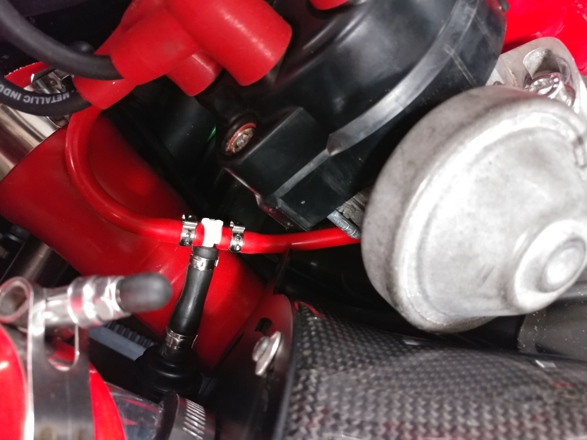
I hooked up the distributor retard port per Dave's diagram.
I also got some input from Jim Doerr on how to create a starting setting for the mixture screw on the K-Jet. I fully leaned the mixture screw (CCW) until it stopped, then jumpered the fuel pump relay, an opened the mixture screw (CW) until I heard the gas squealing, then closed it CCW until the squealing ceased, which took about 1 turn.
I'm still struggling with the advance connection for the distributor as I had Ron AirtekHVAC look at his 82 Euro that has K-Jet and and a vacuum advance and retard distributor and his advance line is coming off the most passenger side port on the throttle body on the side opposite the idle screw and where the retard line is connected.
However, on my car that port was previously used to link two additional vacuum diaphragms. From that throttle body port, the line goes to a side port on a secondary vacuum apparatus and then coming off a center port on that same apparatus, a line goes to the center port on a larger diaphragm apparatus and that larger one is connected to the throttle body by a large diameter line that's labeled "vacuum control port" on the drawings I've been able to find.
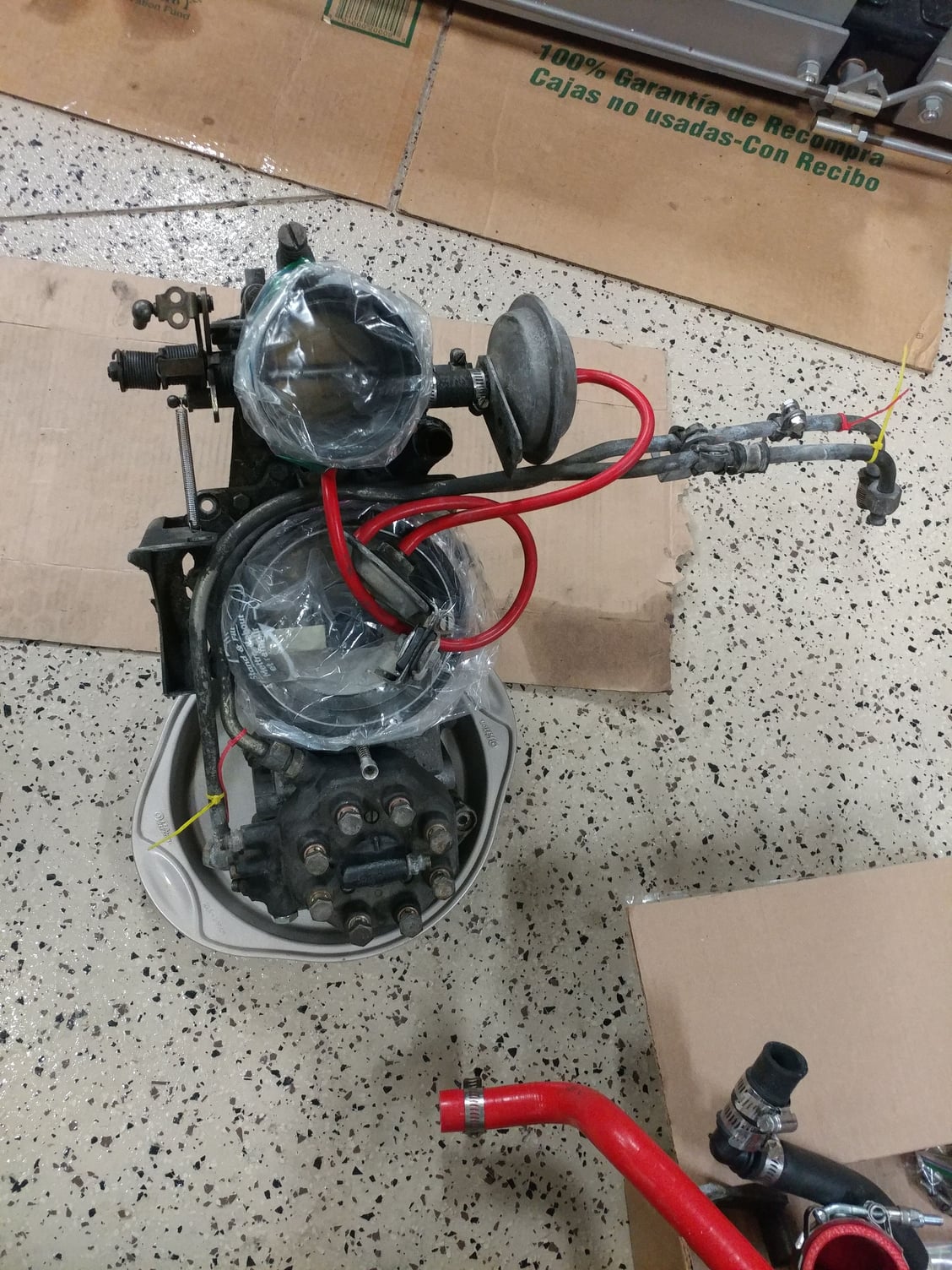
Here's my distributor retard port setup now. Line comes from the port next to the idle control screw
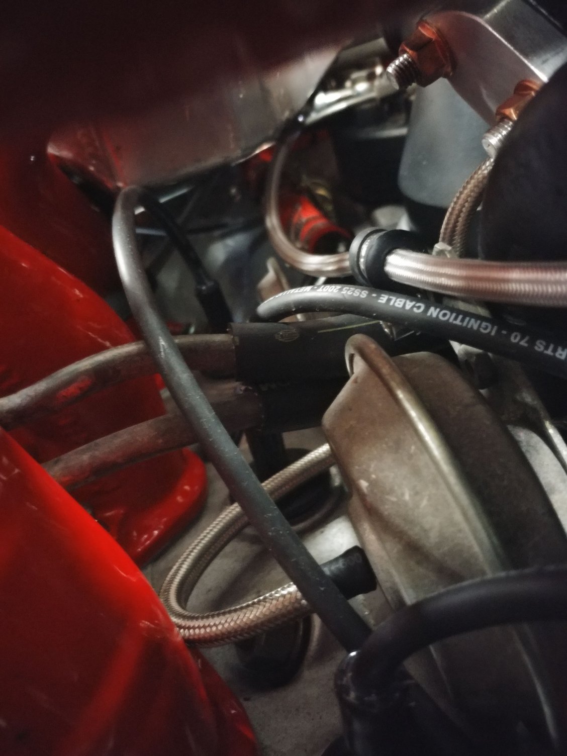
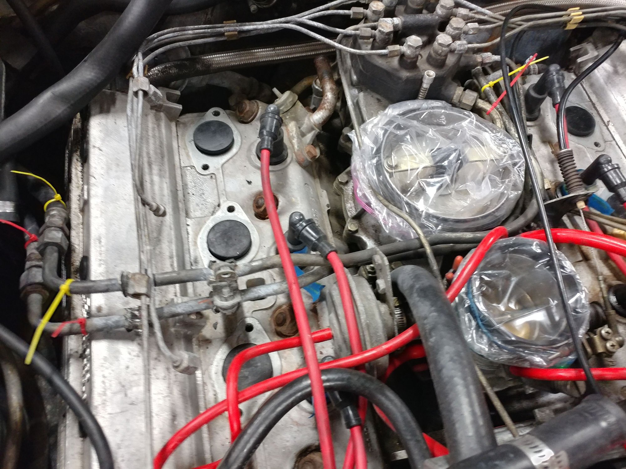
Braided stainless lines are fancy vacuum lines, not fuel. Here's the smaller vacuum apparatus fed by the port off the throttle body that Dave and Ron say should feed the distributor advance port, and then a line from it feeds that larger diaphragm apparatus (next pic)
Foreground is the larger vacuum apparatus connected by a large hose to the "vacuum control port"
Didn't have much time today, but did a few things
There was a capped off port right next to the one Dave and Ron say goes to their distributor advance port, so I uncovered that one and hooked my advance line to it. Don't know if that will work and those ports next to each other are multiples of the same thing or not.
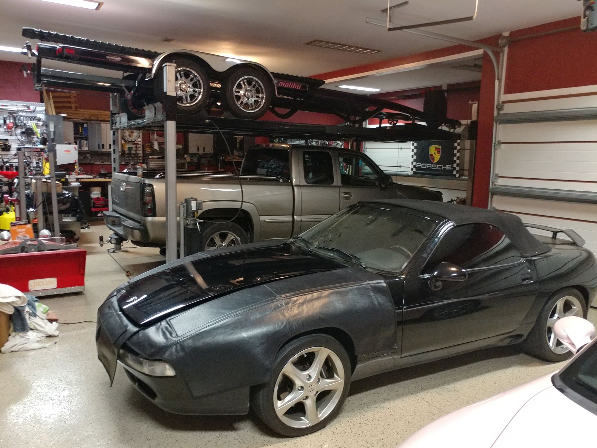
So after all this, I had to get the boat trailer out of the driveway due to neighborhood covenants and it being out there since I started this engine swap project so I had to move the 928.
It started on the third set of cranking attempts and fired up rough, but actually smoothed out a bit after that and the RPMs rose to about 1,500 like they always do on a cold start. I put it into reverse and was relieved to see the car went into gear and letti g the clutch out was smooth and it engaged and backed the car up at idle speed, though the pedal engaged higher than it used to. Moved it into the driveway and shut it off.
Moved the trailer onto the lift and went to move the car back into the garage. Took 3 attempts to start again and I had to move another car and it sat in the driveway and idled for probably 2 minutes, a little rough, before dying. Restarted on the first try and I pulled it into the garage, but this time the clutch made a squealing noise and the pedal didn't feel right and the clutch didn't really disengage as cleanly as when I backed it out. What does this clutch behavior tell you I need to look at?
On the positive side, I did get the hood back on and aligned, and it closes, so it looks like a car again, and there also isn't anything dripping under the car (yet).
Looks great Pete. I remember two ports very close together at the rear of the TB, and I used one of them for my advance connection. You can test with a boost gauge once you have the car running right. Your install is definitely first class.
Thanks,
Dave
How can the distributor go in 180 degrees out. It has the lock down tab that the bolt goes through. Don't you rotate it before installation so that once installed the rotor points the scribe mark on the top edge of the distributor housing? When you press it in, because of the angle of the gears it rotates clockwise as they mesh, which brings up a question.
With the motor at TDC, should the rotor be on the scribe mark before installing, which actually makes it clocked past it when installed, or should it be set slightly before the scribe mark so that it's on the scribe mark once installed?
Also, where in the slot does the lock down bolt usually end up when the timing is correct. Mine was toward the front of the slot but not all the way before I removed it.
Originally Posted by Petza914
Might be a dumb question, but how many times does the distributor rotor rotate per revolution of the harmonic dampener? Is it a 1:1 relationship or could it be that I need to rotate the engine around one more time and then set the distributor position. Maybe this is what was meant by it being 180 degrees out.
The distributor is tied to the cam. It turns one half turn for every turn of the damper (crank). It's possible to install the distributor 180 degrees out, but it wouldn't start. At all. The spark would be firing when the piston was at the top, but when the exhaust valve was closing and the intake was opening. No fuel/air mixture, no compression, no 'kaboom'.
The distributor should be 'started' a bit early. The gears are helical cut so the rotor turns a bit as it goes 'down the gear teeth', you want the scribe mark 'dead on' when it's seated.
The lock down bolt will end up where it ends up. You may be a tooth off in one direction or another, the rotor may not be in the exact same spot (if you removed it), the gear may be on the cam 'just a bit' differently for the new motor. There's a lot of variables that will affect exactly where the bolt ends up in the slot. You are more concerned with the timing being correct.
I played around with the car some more today. Put in new plugs that are properly gapped at 028.
I can make the car run, but the idle still hunts and when the idle is falling the mixture is rich. When I Rev the motor, it gets lean. If I hold the pedal to make the RPMs go to 2,500-3,000 the AFR is decent for a few seconds then gets lean, like up to 17. Either I haven't turned the mixture screw to the rich side far enough yet or something else is going on. The AFR at idle is very rich, like at 10.
The car won't Rev with a timing setting around 20 degrees BTDC and is much better at 28 degrees. Might be better still at 30 or more, but I'm concerned about going up that high.
When I shut off the motor I can also hear the fuel squeaking as it continues to run in. Does this mean the mixture screw is too rich and if so, how can it be too rich when I revit up and the AFR gauge is showing that its too lean?
I also tested it without the supercharger hooked up and it does the same thing, but the mixture at idle is even richer.
Thoughts?
On the plus side, I took the clutch out again last night and lubed the splined shaft with the proper grease and it seems to work very smoothly now, though I haven't moved it off the lift yet.
On the plus side, I took the clutch out again last night and lubed the splined shaft with the proper grease and it seems to work very smoothly now, though I haven't moved it off the lift yet.
What is the proper grease? Do you have a link to it?
When I had the 79 it did weird things when the fuel pump intake was collapsed and the intake pump died.
But why would it just now with the new motor start exhibiting this behavior when it had run perfectly with the prior engine? Nothing in the fueling system is different, actually, nothing except the fuel lines. With mechanical injection, if the fuel lines are larger, is it possible the injectors are seeing different pressure pulses from the fuel distributor?
If there's any possibility of that, I'm thinking about reinstalling the original hard metal lines. The injectors are all brand new.
I also figured out why my Knock-Link sensor wasn't initializing.
As you'll recall, I installed this while the battery was disconnected for the rest of the engine work and installed the light in the rear wiper position of the dash pod, so couldn't test the wires for switched 12v.
Well, I had two problems
I wasn't getting any voltage on any of those wires when I tested them with my meter tonight. Looking at the fuse panel, because my car is a convertible, I had actually pulled the fuse for the rear wiper to prevent the possibility of a short in the wiring since it wasn't connected to anything.
I had guessed at the wrong switched 12v wire going to the wiper switch. I had used the green one and testing it tonight, the 12v switched wire is the black and purple stripe one, which is actually 2 wires into a single female connector.
Installing the fuse and connecting to that wire now has the red light, then blue flashing light, then green light coming on, though I haven't started the car yet, just tested the initialization sequence.


 06-02-2019, 09:40 AM