When you click on links to various merchants on this site and make a purchase, this can result in this site earning a commission. Affiliate programs and affiliations include, but are not limited to, the eBay Partner Network.
Even though today has been extremely busy I am very happy and thankful for having my car back on road on a beautiful sunny day. There's something truly special about driving a GT3. I don't have the latest and the greatest model nor a concours car but I thoroughly enjoy everything about mine, including the imperfections and quirks. And this is more than a fun car, I actually put it to work. See, I use it to test DSC modules and accelerometers for customers on our local "test loop". Wink-Wink.
Speaking of accelerometer, I have relocated my DSC 3-axis accelerometer to be above the aluminum plate instead of below the plate. There's no performance advantage I just like the way it looks. The Cup cars have their accelerometer exposed in the middle of the car so I'm going for the petite Cup look.
I even carved out a piece of foam on the covering to accommodate the accelerometer on top of the plate but decided to leave the covering off because I want to hear all the sounds the covering dampens. With the LWFW it sounds a little closer to a Cup. Petite Cup sound.
That's a substantial increase in mid-range torque and I definitely felt it by before dyno'ing to confirm. And a solid 10hp at the wheel compared to the best run from last March after service! Have no idea if the gains were from the fresh lifters, cam actuators, chain tensioners, oil guide tubes or combination of all of the above. Regardless, I'll take what I can get.
Last edited by Tom@TPC Racing; 03-19-2015 at 02:12 AM.
Any chance that you can post a 'How to' on cam alignment on this beast?
Here you go-
This is assuming the engine is already on a stand, with heads and cam housings on the block, and cams ready to be installed. This is the way I timed the cams on my .1 engine, there are other ways and sequence to do this, and for other model the procedures may differ. The contents are for your entertainment purpose only, I have no accountability should you attempt to do this at home at your own risk.
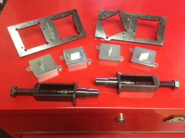
1. Install intake and exhaust cams on Bank 1 & 2. The cams must be installed in such a way so that the none of the valves contact the pistons when turning the engine by hand; Bank 1 Cyl. 1 intake and exhaust lobes facing toward each other. Bank 2 Cyl. 4 intake and exhaust lobes facing away from each other. There are factory metal templates to achieve the position of the cams for some models. I borrowed the cam fixtures and the square pucks from our in-house engine builder. The square pucks are uniquely clocked for each cam and for each model engine.
Fixtures, pucks for specific model, tensioning tool.
Without the fixtures and the pucks, one would have find the centerline of the cams the old fashion way, that's if the centerline specs relative to crank angle degrees is published for the particular street car model. The theory of it can get even more complicated when factoring in vario-cam actuators which in this model has range of movement up to around 50 degrees! It gets complicated when I think about all that could go wrong with this much range of movement. BUT, its really simple when I have no choice but to trust the engineering. The simplicity is the cam can be a couple degrees out of time(due to wear or margin of error) and the vario-cam system will "dial in" the cam based on position of the built-in reluctor wheel. In the case of the .1 engine only the intake cams have actuators. The exhaust cams are fully mechanical so timing the exhaust cams precisely will direct impact on cylinder pressure.
2. Once the cams are positioned, install the fixture and pucks only finger tight, then the intake and exhaust sprockets(the intake sprocket on .1 engine is part of the vario-cam actuator) only finger tight. Again, only finger tight because at this stage the sprockets must be able to turn independently while the cams are locked by the fixtures and pucks.
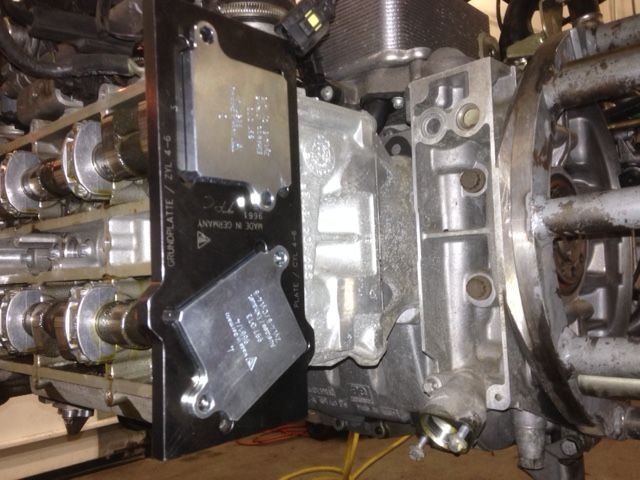
Bank 1 cam position locked in.
Bank 2 cam position locked in.
3. Install the temporary mechanical chain tensioning tool on Bank 1 & 2. Set chain tension. Slowly and very carefully turn the engine clockwise 360 degrees to make sure there's no valve contact. After that turn the engine clockwise a few more times to settle the chain tension.
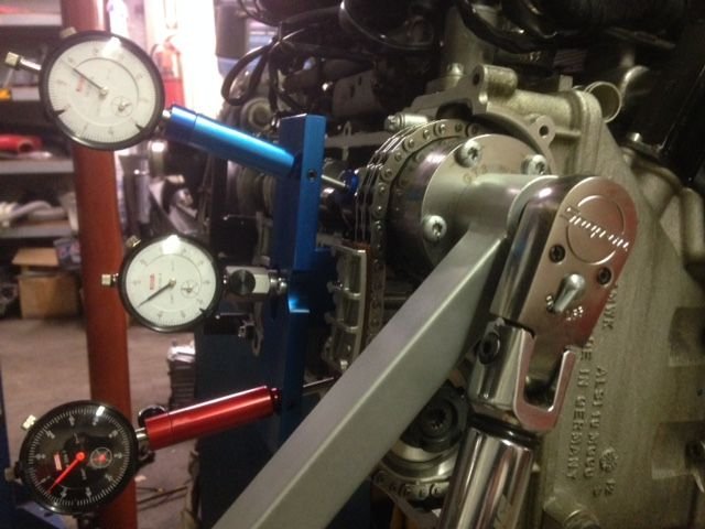
4. Once chain tension is settled the next step is to find TDC(Top Dead Center) on Bank 1 Cyl. 1. There are different methods for finding TDC, do a google search and find the method that appeals to you. Some prefer the use of a degree wheel while others use the notch on the crank pulley. Either way you must have a dial indicator. Well, actually that's not true if you feel the notch on the crank pulley is sufficient. There's about a 6-degree dwell at which the piston is stationary at TDC. For mass production and general repair purposes, the engine will run anywhere within that 6-degree range(and don't forget about the whole vario-cam actuator adjustment range which should dial in the cams for the margin). And there's the term "True" TDC which is exactly in the middle of the dwell. In theory, the cylinder pressure is at optimum when cam centerline is at True TDC. As a passionate person I strived to find True TDC. Even with the best dial indicator and the highest resolution(diameter) degree wheel the results are not always 100% repeatable when reading the indicator gauge at value of <0.001 inch especially when not on a brand new or freshly cleaned piston top(gauge reading might deviate from carbon on unclean piston top). But at such measuring increment(fraction of 0.001 inch) it is literally splitting hair. I have found my True TDC to be not exactly centered to the notch on the stock crank pulley(see photo) which could just be the how this particular pulley was made. Also the factory manual reads as such that their depiction of TDC is turn engine until reversing point on the dial indicator. To me, seeing reversing on the indicator gauge is technically passed actual TDC even if its a fraction of 0.001 inch. IMO, the definition of TDC in this application is really up for the operator's interpretation and discretion, again, we are splitting hair with fraction of 0.001 inch/fraction of one degree. Since this timing procedure is based solely on timing Cyl.1 & 4 we have to presume that the stock cams are accurately ground along the length of the cam from one cylinder to another.
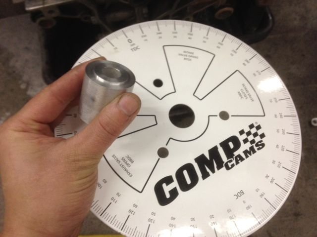
Here's my engine at TDC Bank 1.
I bought a universal degree wheel and machines a crank adapter out of an aluminum slug off an old control arm.
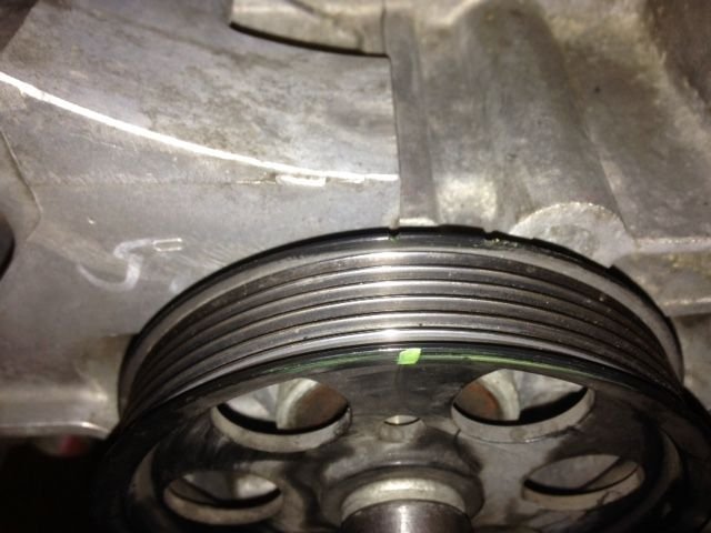
With my engine at True TDC this is how the stock crank pulley notch lines up. Some may line up better than others.
5. Once TDC was found by turning the engine clockwise, then pre-torque Bank 1 intake sprocket to 37 ft-lbs and exhaust sprocket to 22 ft-lbs. Remove the fixtures and pucks. Next step is the final torque which is not expressed in resistance value, its in degrees of rotation(angle) of the fastener. For the intake sprocket its 110 degrees from pre-torque value. For the exhaust sprocket its 90 degrees from pre-torque value. FWIW, my SnapOn Tech-angle torque wrench also displays torque resistance which came to 149-155 ft-lbs for the intake and 118-122 ft-lbs for the exhaust the number of times I did this.
Final torque on intake cam sprocket/actuator.
6. Turn the engine 720 degrees clockwise(two complete turns) to TDC. Post-fit the fixtures and pucks on Bank 1. Bank 1 is now timed.
7. Turn engine 360 degrees clockwise(one complete turn), use a dial indicator if you wish, to find TDC on Bank 2 Cyl. 4. Perform the pre-torque, final torque, and post-fit on Bank 2 intake and exhaust sprockets. Bank 2 is timed.
8. Remove the temporary mechanical chain tensioning tool and install the hydraulic chain tensioners.
I took an extra step of using the Stomski Racing Cam Timing Apparatus to find out the cam centerline relative to crank angle. I find this equipment to be high quality and accurate. Using this equipment I came up with intake centerline of degrees 140-141 ATDC, exhaust centerline of 115-116 BTDC.
Last edited by Tom@TPC Racing; 03-19-2015 at 07:47 PM.
Reason: added one more photo
its good to see this here as a FYI. Gives people a idea of some of the detail in engine building and why there is a cost- time and specialist tools aside.
its good to see this here as a FYI. Gives people a idea of some of the detail in engine building and why there is a cost- time and specialist tools aside.
Yes agree completely on FYI, not DIY. Often the steps have to be repeated when something doesn't feel right. The "feel" is an important element, it takes a lot of mechanical experience in the profession to develop. Catastrophic(and very costly) damage can occur with one mistake.


 03-17-2015, 10:16 AM