When you click on links to various merchants on this site and make a purchase, this can result in this site earning a commission. Affiliate programs and affiliations include, but are not limited to, the eBay Partner Network.
Ran mine at Sebring for the first time using the stock tables and I can report a noticeable improvement in handling. Much more planted in the turns and far less nose dive when braking hard. I had a 1 second improvement in track time and I'm certain I'll get another .5 to 1 second improvement next time out.
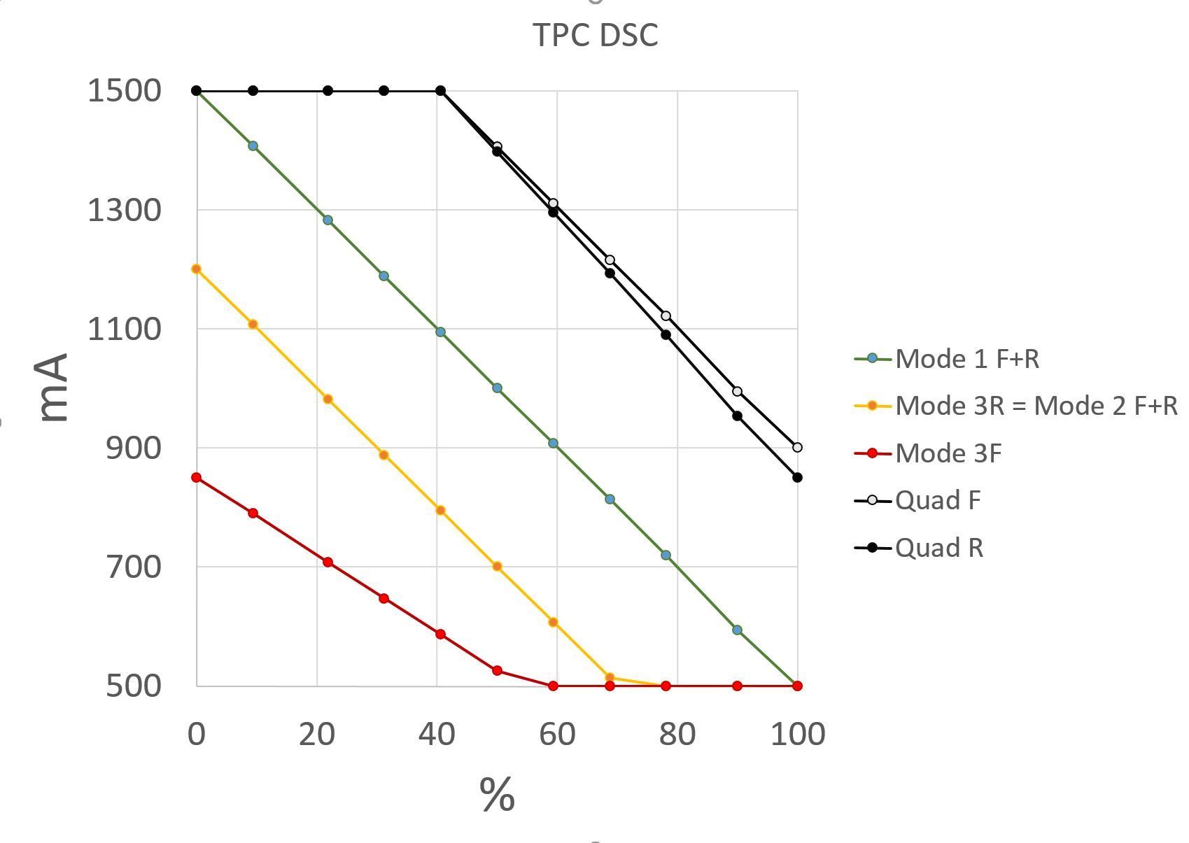
If anyone's interested, I mapped out Modes 1, 2, and 3 using the DSC Sport software. Please correct any errors if you see any.
Mode 1:
Linear and covers the entire dynamic range of the shock from full soft (1500) to full stiff (500). F/R maps are the same.
Mode 2:
Stiffer than Mode 1 and with less dynamic range. Softest is 1200 mA. Full stiffness at 70%. F/R maps are the same.
Mode 3:
Rear map is identical to Mode 2. Front map is even stiffer than Mode 2, and with even less dynamic range. In the front, the softest is 850mA. And full stiffness occurs at around 50-60%.
Quadcammer Mode:
Is full soft (1500mA) up to 40%. Then progressively stiffer to about 900mA as the stiffest setting.
The way the software seems to work is that for each Mode setting, you can program the mA (=shock stiffness) for each incremental %. There is a built-in map that correlates G's with the %. Interestingly, the default G-force to % map seems to be the same for all 3 modes. And for 0-0.2g in any direction, the mapping appears to be 0%. And at 0.4g, the mapping jumps up to 50-60%.
Hope this information can help people who want to make their own custom maps.
Very nice work, the graph helps to understand what's going on for correlating final calculated % stiffness to shock mA's of control.
Originally Posted by gasongasoff
The way the software seems to work is that for each Mode setting, you can program the mA (=shock stiffness) for each incremental %.
Correct
Originally Posted by gasongasoff
There is a built-in map that correlates G's with the %.
G-force is mapped to percent as you say, but so is speed, brake pressure and steering angles. These are all combined into a single calculated % stiffness number. Only after combining these inputs and ending at a single % stiffness is a lookup done to convert that combined % stiffness to mA to control the shocks.
Originally Posted by gasongasoff
Interestingly, the default G-force to % map seems to be the same for all 3 modes. And for 0-0.2g in any direction, the mapping appears to be 0%. And at 0.4g, the mapping jumps up to 50-60%.
The takeaway is that the g-force table has no real input to the % stiffness calculation until the sensor reads over 0.4, then g-force's impact on stiffness becomes larger.
Let's use cruising at highway speeds as an example. At highway speeds the g-force input is close to zero so it's effect on stiffness is almost nothing. Brakes are not pressed so their input is zero. But the speed table is calculating a % stiffness greater than zero percent. The actual stiffness percent is somewhere greater than 0% but less than the 50% when the g-tables start to kick in. Similar things happen while braking lightly keeping the g-forces at moderate levels. Slam the brakes though and both the brake pressure and g-force inputs affect the % stiffness greatly. Use the DSC software to log the actual inputs from the g-sensor, speed, brake pressure and steering angle, along with the actual mA value sent to each corner and you can get a better picture of how these inputs are combined in real life. I've found exporting to Excel then using the graphing features built in helps, tedious yes, but helps.
But at the end of the day you only need to adjust the shock table lookup which converts the final combined % stiffness to shock control mA. The DSC box's other table mappings work quite well with default values. Tweaking the other tables is really more for specialized applications.
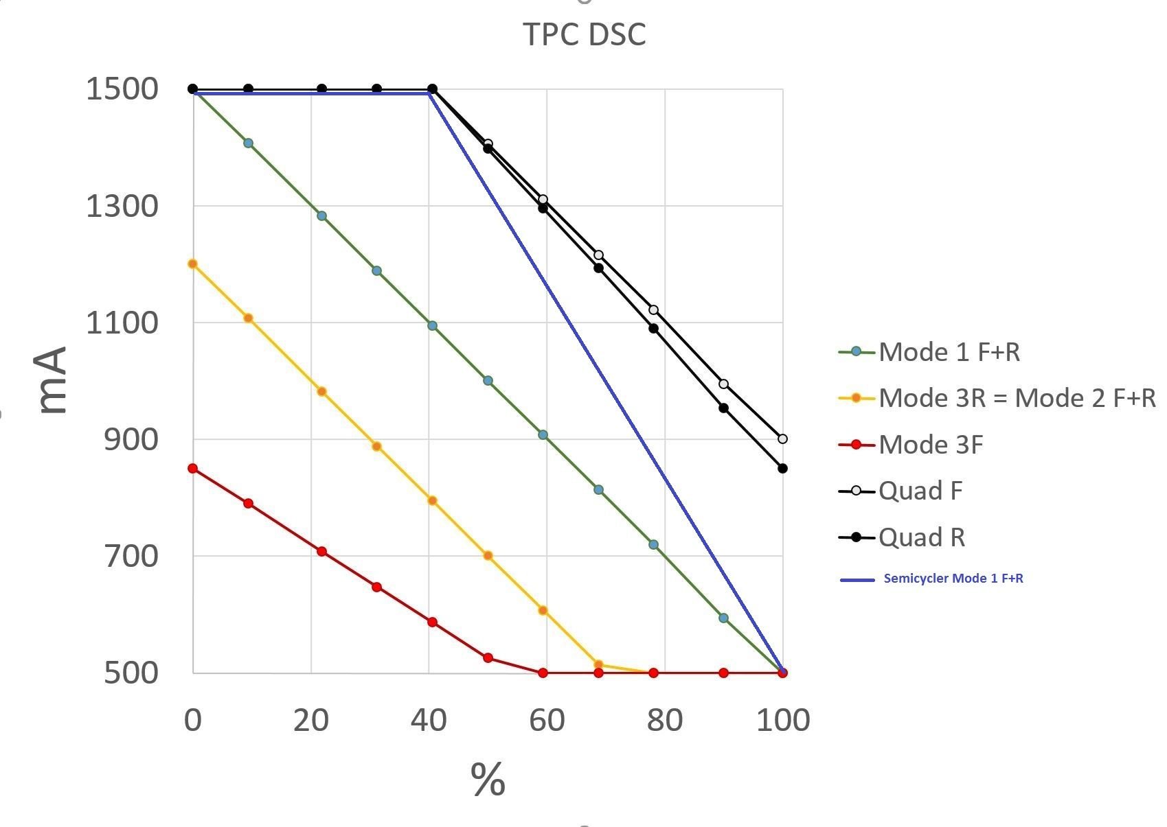
edit to add my Mode 1 settings to the graph, soft like Quadcammer for 0%-40%, then stiffens up faster. I call this "wife mode". Normally I drive alone in mode 2.
Last edited by semicycler; 02-17-2016 at 10:27 AM.
Great information, appreciate your efforts and willingness to share. What is the logic behind the mode 3 setting that has the front stiffer than the rear? Isn't this going to result in increased understeer?
Great information, appreciate your efforts and willingness to share. What is the logic behind the mode 3 setting that has the front stiffer than the rear? Isn't this going to result in increased understeer?
Great information, appreciate your efforts and willingness to share. What is the logic behind the mode 3 setting that has the front stiffer than the rear? Isn't this going to result in increased understeer?
I'll see if I can get some more info from our set up engineer on this, but as far as I know it was to increase grip to put the power down on corner exit. The softer rear reduces oversteer on corner exit.
Aren't "increased undetsteer" and "reduced oversteer" two different ways of saying the same thing since both are relative terms? I think you're all in agreement on the reason.
Aren't "increased undetsteer" and "reduced oversteer" two different ways of saying the same thing since both are relative terms? I think you're all in agreement on the reason.
Just curious, is there a maximum downwards slope of mA vs. %? (in terms of exceeding the ability of the suspension to respond or worse, misbehave). I notice that the default modes all follow the same slope, perhaps it was intentional?
G-force is mapped to percent as you say, but so is speed, brake pressure and steering angles. These are all combined into a single calculated % stiffness number. Only after combining these inputs and ending at a single % stiffness is a lookup done to convert that combined % stiffness to mA to control the shocks.
That's a really helpful explanation, thanks for taking the time (and for adding in your mode 1).
Use the DSC software to log the actual inputs from the g-sensor, speed, brake pressure and steering angle, along with the actual mA value sent to each corner and you can get a better picture of how these inputs are combined in real life. I've found exporting to Excel then using the graphing features built in helps, tedious yes, but helps.
G-force is mapped to percent as you say, but so is speed, brake pressure and steering angles. These are all combined into a single calculated % stiffness number. Only after combining these inputs and ending at a single % stiffness is a lookup done to convert that combined % stiffness to mA to control the shocks.
I just noticed that my steering angle table is blank (all 0%). Same with accel (all 0%). Is it like that on yours too, or did I screw something up?
I just noticed that my steering angle table is blank (all 0%). Same with accel (all 0%). Is it like that on yours too, or did I screw something up?
All good mate! The steering and accel tables are not used at this point. Accel table may be used with the new 991 Turbo S in the future. DSC is using this feature on the Viper and Corvette. Cars that can overwhelm the rear tires with ease. P-Cars in stock trim don't have this requirement.
Hello all,I recently had a great conversation with Mike @ DSC / TPC. We went over the tuning software in detail and I took some good notes. I have a few questions in regards to some the numbers in the 3 mode software GForce parameters still, But aside from that, I feel like this is a great foundation for everyone to build on!
.
DSC tuning software info
G Comfort parameters (GForce Thresholds) � Default rate (Lng Rate) = This is the �Default� soft shock setting when operating inside the �patch� or �box�. This number is the % from the shock calibration table. So if a 1 or 15 is present, 1% or 15% of the shock calibration will be applied. The early 3 mode units have 60 here. Need to confirm if this equates to 60% of the shock calibration or if a different method is used. ?? � Lat rate = This is a calculated value and is always set to 100 on the new units. On the early 3 mode units, this is set at 60. � G Rate MAX = This number defines the �box�, the G Patch. You need to move the decimal to the left 2 places, then you view this number as a G force value. So if we have a 20 present, that would be .2G. Within this .2G box, the Default rate (Lng Rate) applies. The size of the box can be from .3G to .1G, anything outside of this can have some un-desirable effects. � Sensitivity (rate trigger) = This is the rate of change within the box, the Patch. The greater the number, the higher the sensitivity. This means the you will not deviate from the Default rate (Lng rate) as quickly. The smaller the number, the lower the sensitivity. This means you will deviate from the Default rate (Lng rate) more quickly. Therefore this is why we have a lower number in �sport� mode (10) compared to �normal� mode (15).
Brake Table � Decay = This table is applied before the G-table is referenced. It is only active for the specified �decay� value. This is usually set to 1000 = 1.0sec. � Pressure = This table is only active when you reach the set brake pressure setting, this is the �Pressure� box, and is calculated as BAR per millisecond. � Speed = Minimum speed at which the table is active. Should be set to 5mph. � Theory = The brake table is used to soften the blow to the front tires, provide more front grip and help reduce ABS intervention. The rear dampers are stiffened to prevent (slow) the weight transfer to the front tires, this also helps reduce the load on the front tires and un-wanted ABS intervention. Protecting the front tires on initial hard brake application. Remember, this is all occurring inside of 1 sec in time. After this time has elapsed, the GForce table is applied, platform, support etc, corner entry phase.
Speed table � This table is used to provide stability as the vehicle speed increases from 10 to 100mph. Over 100mph, the logic is the aero properties of the chassis will provide the stability. � Speed G-limit threshold = Use this to control when the speed table will be active. Units are usually setup with .30G in all 4 values. This means when the car exceeds .3G in any direction, the speed table will no longer be applied in addition to the GForce table. � Speed table calibration = The calibration can be changed the same way the shock calibration can be changed. Clear all values, input your 10mph values and your 100mph values, then click �fill empty� and the system will interpolate the rest.
Shock Calibration � This is the most important and influential table as all other tables reference it. � Damper operating range = With the OEM dampers, 1500ma is to be considered full soft and 400ma is full stiff. The Tractive shocks have a larger operating range. � Building a new shock calibration = To build a linear shock calibration table proceed as follows. Click the �clear all� button. Input the 0% (full soft) values. To do this you must click on the respective cell and input the desired ma in the �calibrated at� box. Then click the �update� box. Do this for all 4 of the 0% cells. Then set your full stiff cells in the same manner. Once you have done this, click the �fill empty� button and the software will interpolate the remaining cells. � Writing the new shock calibration = Make sure that under the read and write box�s, that �all� is selected. Then double check what mode you will be writing this calibration to. To do this, click on the settings tab, take note what mode your are altering, ie �normal� or �sport� and then confirm what mode you will be writing to, �normal� or �sport�. Go back to the shock calibration tab and click the �write� button. It is then a good idea to reset the board. Click the tools menu, select �reset board�. � Tuning with the shock calibration = This is a great way to make global changes. Start with the shock calibration tables then move into the other tables.
Velocity Table � Not active in current software. Should be released soon. � OEM PASM is not using the 4 Ride Height sensors for Velocity calculations. DSC is using this data to calculate Velocity. � When looking at the table, �0� is static ride height, at the current time you will use 3 cells to left and 3 cell to the right of zero. Each cell is 2� per second. So the table will be from zero to 6� per second for compression and rebound. Compression is the Negative values, left side of the table; Rebound is the Positive values, right side of table.
� Velocity will only be available for 9X1 cars as standard, 9X7 cars would need 4 ride height sensors to be fitted and wired. Cup cars can use this table with shock pots fitted.
Commands, A, X and I � Accessing commands = Under the tools menu, select �test serial port�. Click �start�. In the write out box, this is where you will enter either A, X, or I. � A command = This command is used to set the dampers to full soft, 1500 ma. You can use this function when doing a setup or to test the shocks, wiring, connections etc. Enter A in the write out box and hit enter. It will then prompt you to enter Y or N to confirm your selection. � X command = Use this command to clear fault codes. � I command = Use this command to read out fault codes. Codes are displayed numerically 1-14. Use this command as a diagnostic tool.
Data logging � Under the tools menu, select �switch input� this is where you will select what inputs you wish to record. Click �set� to confirm your selections. � Recording data = Under the tools menu, select �record�. On the display menu, click the �circle� to start recording. The laptop must be in the car and connected to record! Once you are done recording, click the �square� to stop. Save your file in your DSC folder on your desktop. Each unit in the display represents 1 tenth of a second. This is the time domain. � Text view = You can also view the data in a text view. Select the �text� tab next to the �graph� tab to toggle views.


 01-28-2016, 09:31 AM