When you click on links to various merchants on this site and make a purchase, this can result in this site earning a commission. Affiliate programs and affiliations include, but are not limited to, the eBay Partner Network.
Resurrecting this thread. I've acquired a MOST box from Avinusa and a Metra 70-1787 harness connector. Of course also picked up an antenna adapter and fascia to go with the Sony CarPlay head unit. However, I'm having some trouble wrapping my head around the wiring.
Once the stock PCM head unit is removed, the Metra should plug into the harness off the car. Then the pigtails off the Metra should be soldered into the harness that comes with the Sony. The fibre optic cables off the car should then plug into the MOST adaptor. The RCAs from the MOST adaptor plug into the Sony. I get all that.
But I can't seem to find anything definitive showing which wires to solder to which from the Metra to the Sony adaptor. I believe that none of the speaker wires are soldered, ie. the positive and negative front and rear, left and right speaker wires. But then looking here:
which terminals off Plug A correspond to the Metra and then to the Sony? The markings on the wires off the Metra are red (12 volt ignition/switched), orange (dimmer), yellow (12v batter/constant) and black (ground).
The link I posted is from the 996 forum, but my 997.1 should be comparable, except that there are the optical connections and there shouldn't be any speaker related wires. And then what do I do about plug C?
Any help appreciated. I know this is pretty basic stuff, but I'm quite bad with figuring out electrical - once I know what to do though, I can solder with the best of them!!
I vaguely remember that the 70-1787 cannot be used as-is => You will need to switch the power cable location - or remember that the colors are switched .
Check the video I linked a few posts above. That should have a full walk through of how to wire the connections.
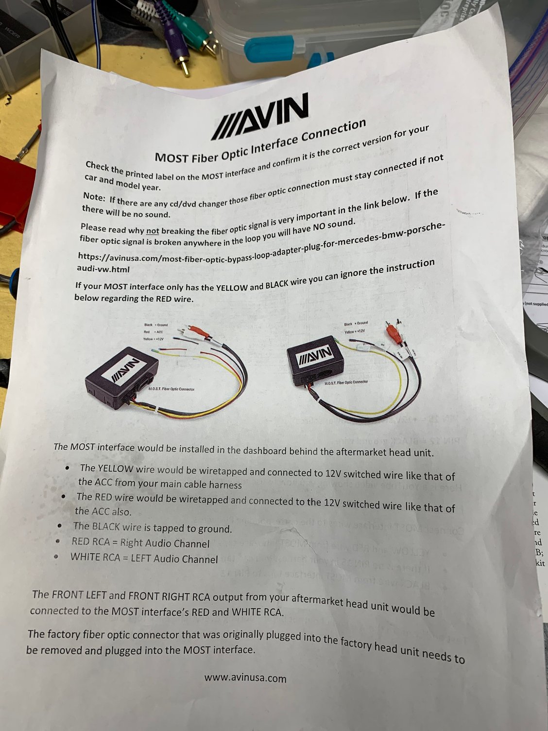
The MOST box connections are very simple. The Head Unit wires should be documented in the manual, or you can just lookup online.
You are correct in that none of the speaker wires will be used, so you can trim them and seal them with some electrical tape.
I vaguely remember that the 70-1787 cannot be used as-is => You will need to switch the power cable location - or remember that the colors are switched .
Check the video I linked a few posts above. That should have a full walk through of how to wire the connections.
The MOST box connections are very simple. The Head Unit wires should be documented in the manual, or you can just lookup online.
You are correct in that none of the speaker wires will be used, so you can trim them and seal them with some electrical tape.
Thank you! I didn't realize the video covered that stuff. I'll check it out.
I was looking at Alpine ILX-W650 from Crutchfield. The package included the unit, all wiring harness and surround unit for about $650. Any comments? This retains the Bose and I do not have steering wheel controls.
Hi there...did you get this done? I have the same unit/harness and can't seem to get it to power on. Did everything as instructed, although the blue/blue white connection (2x) was very confusing. I called customer service and followed their instructions but it still didn't seem right. Any thoughts...?
Getting stuck into this project. Ignore the link I posted above with the wiring diagram, it’s probably good for 9x6s and maybe 9x7s without Bose, but not for 9x7s with Bose.
Anyway, watching the video posted in page 14 or so, they circle back to the amp wire (white off the chassis harness, blue in aftermarket). It seems they pin the blue connector into the aftermarket harness do that once off the chassis, it goes to accessory/switched power. Is that correct? But then the blue amp wire off the aftermarket head unit doesn’t get hooked up to anything at all?
Getting stuck into this project. Ignore the link I posted above with the wiring diagram, it�s probably good for 9x6s and maybe 9x7s without Bose, but not for 9x7s with Bose.
Anyway, watching the video posted in page 14 or so, they circle back to the amp wire (white off the chassis harness, blue in aftermarket). It seems they pin the blue connector into the aftermarket harness do that once off the chassis, it goes to accessory/switched power. Is that correct? But then the blue amp wire off the aftermarket head unit doesn�t get hooked up to anything at all?
Hey Saaboteur, Could you give more details on which Sony HU you are trying to install? That way we will know which harness it is and can help you better.
--shyam
The one I'm talking about is the blue/white striped, wire #4 in the Sony diagram.
I think I answered my question though, or at least the first one.
Off the chassis, the white wire should connect to the Metra harness's blue/white wire; then that blue/white needs to tie into accessory power. I've seen references to that throughout the thread (shame on me for not reading it in complete detail though).
And from the Sony manual, I think they say you can just leave the blue/white striped, wire #4 unconnected (per their comments on page 29 of the manual).
Oh yes - this thread has a lot of info over the pages and over the years
I'm not sure about the factory white wire being a switched accessory signal - if you've come across this, the might as well try it out.
The idea of the blue-white wire from the HU is to signal the amplifier to turn on and off. So this should feed into the red wire for the MOST box.
The HU's Red wire should be connected to a switched accessory power - this is to turn on and off the HU itself.
The reason why you want the HU to direct the amplifier on/off is because only the HU knows when to turn it on and off - otherwise you will hear popping sounds when switching it on and off.
I've used the fuse suggested in this thread before and that has worked well. If you've read that the chassis white wire can be used authoritatively, then try it out (possibly test with a multimeter first).
Oh, I hope I didn’t confuse - I meant the white wire off the chassis needs to be connected to 12v switched / accessory power, not that it is 12v switched / accessory.
Oh, I hope I didn�t confuse - I meant the white wire off the chassis needs to be connected to 12v switched / accessory power, not that it is 12v switched / accessory.
and per the YouTube video on page 14, I�m going to feed 12v switched / accessory power to the white wire.
And then the blue/white from the Sony harness will not lead to anything.
when I�m finished I�ll either do up my own thread with details of exactly how I wired everything, or I�ll post it up here, or both!
Now I understand the white wire better - it is to turn on the radio antenna amplifier/booster. I've ignored that wire and have been fine with the reception.
But then I don't listen a lot to the radio. So if it benefits the reception, then do it by all means.
So if your blue/white from the Sony HU is not going anywhere, what will control the timing of the MOST Box (and the amplifier) switching on and off?
I'm intending to connect the MOST box to 12v switched/accessory power, and also one to 12v battery/constant, and of course ground too. That should be sufficient, no?
There is 12v battery/constant and ground on the 'C' connector off the chassis, but not accessory power. For the accessory (and also parking brake and illumination) I'm following the CAI DIY instructions for connections off the harness behind the HVAC controller and cubbyhole.
I'm intending to connect the MOST box to 12v switched/accessory power, and also one to 12v battery/constant, and of course ground too. That should be sufficient, no?
Yes, the cheaper MOST boxes (other than NavTV MOST-HUR) all have only those 3 wires. But if you connect the MOST box directly to a switched/accessory power, then it means that the HU and the MOST Box would be switched on/off at the same time - and this will most certainly result in popping noises. That is why you let the HU decide when to switch on/off the amplifier (via the MOST Box).
You could try using the switched/accessory power directly.. see how it turns out, and then decide too.
The blue/white amp wire off the Sony also needs to connect to switched power.
But then in the YouTube video with the two guys, it seems they connected the white wire off the chassis to switched power, and not the blue/white wire off the head unit to switched power. That said, they have the red CAN Bus connector (re-pinned though) and I don't have that because I'm not using the NAV TV MOST adaptor.
In my test run, I have the blue/white amp wire off the Sony going through to the white wire off the chassis. But no sound. Some weird noises from the sub but no sound at all otherwise. That seems to me that the amp isn't turning on at all.
a direct connection from the rear speakers to the aftermarket deck is possible? they run off the same amount of resistance?
Originally Posted by Skidly
I have been doing some thinking about how to get the fader to work....and now the answer seems simple.
Most modern head units have 5 outputs Front left and right. Rear left and right and sub woofer.
MOST kit you can connect the front left and right to the MOST25 kit.
Disconnect the rear left and right speakers from the OEM amp on the amp the left rear speaker wires are the White and white brown wires and the right rear speaker wires are the blue and blue/brown wires)
Reconnect these wires directly to the left and right rear outputs respecitvely directly on the head unit.
This will allow you to use the fade function on the amplifier.
The blue/white amp wire off the Sony also needs to connect to switched power.
But then in the YouTube video with the two guys, it seems they connected the white wire off the chassis to switched power, and not the blue/white wire off the head unit to switched power. That said, they have the red CAN Bus connector (re-pinned though) and I don't have that because I'm not using the NAV TV MOST adaptor.
In my test run, I have the blue/white amp wire off the Sony going through to the white wire off the chassis. But no sound. Some weird noises from the sub but no sound at all otherwise. That seems to me that the amp isn't turning on at all.
ok, let's clear this up NAVTv and the other expensive MOST box kits also have a CANBus decoder module that takes more inputs and gives out more output signals. In my current setup I have the Connects2 kit which also has a steering wheel control module so I can keep my multifunction buttons. These kits that take in the CAN Hi and CAN Lo signals also know to emit a switched/accessory power output signal. This is what is sent to the HU in those kits as their switched/accessory input signal. And in this case, we won't need to tap an ignition-controlled accessory source from the fuse box.
Since you don't have a CANBus module, you have to get the switched/accessory signal from the fuse box - no idea where the white wire came into the picture here.
The blue/white coming off the HU is an amp-turn-on output signal. And this will go as the input signal to the MOST Box to turn on the amplifier.
So the blue/white wire from the HU needs to be connected to the Red wire of the MOST Box.
Acc/Ignition wire coming from the fuse box => Switched/Power signal to the HU
Blue/White wire from HU => Red wire in the MOST Box
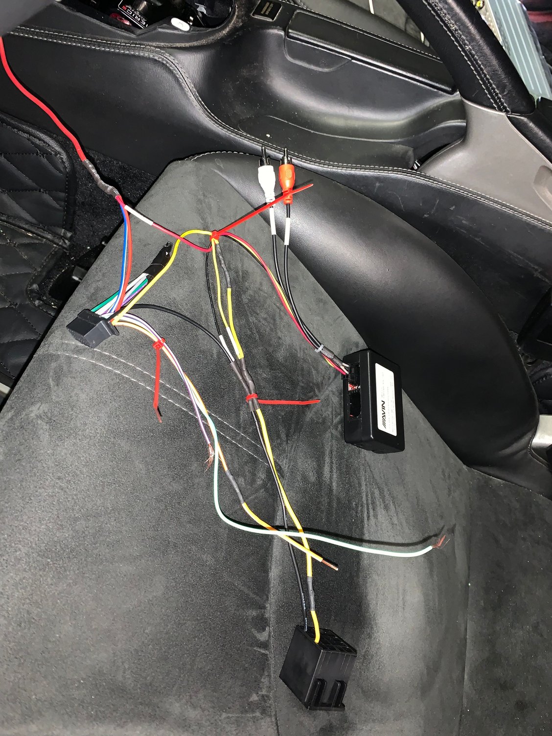
Okay, now doubly confused. I rewired everything per my picture attached (explanation below) and whilst the head unit turns on with the ignition, it won't shut itself off! Also, the sound cuts in and out, I jiggle the MOST adaptor connector, the fibre optic connector to it and the RCA plugs, and it gets sound, so I think something may be just slightly loose. But the head unit not turning itself off is a bit worrying!
Off the head unit harness, I have red 12v switched wire soldered to the blue/white wire, and also the red wire off the MOST adaptor. These are all soldered to a larger, thick wire which I then tapped into the orange accessory/switched wire off the harness behind the HVAC controls (per the CAI DIY pages). You can see the red wire trailing off into the top of the photo, as I didn't want to disconnect it and further aggravate the orange wire.
The yellow 12v battery wire off the head unit harness is soldered to the yellow wire off the MOST adaptor, and then connected to the Metra adaptor, which then connects to the chassis harness red/green (battery power).
The black ground wire from the head unit harness is also soldered to the black wire off the MOST adaptor, and then both soldered to the ground wire connected to the Metra adaptor, which of course connects to the brown wire off the chassis harness.
The remaining wires near the bottom of the picture are the reverse (which will connect to the lead off the yellow RCA leading to the camera); green wire to the parking brake, and another yellow wire (which is actually just an extension of the orange/white dimmer wire) from the head unit harness (which will go the illumination wire, again using the CAI DIY page).
However, I've noticed the Avinusa instructions say to avoid connecting the yellow to battery power (even though it's labelled as such) and just connect it to switched/accessory power. Could it be that the MOST adaptor is keeping the head unit alive because of the connection to battery power?


 05-04-2020, 02:50 PM
 .
.