

A photo journal of my suspension overhaul.
 06-01-2014, 12:23 AM
#1
Nordschleife Master
Thread Starter

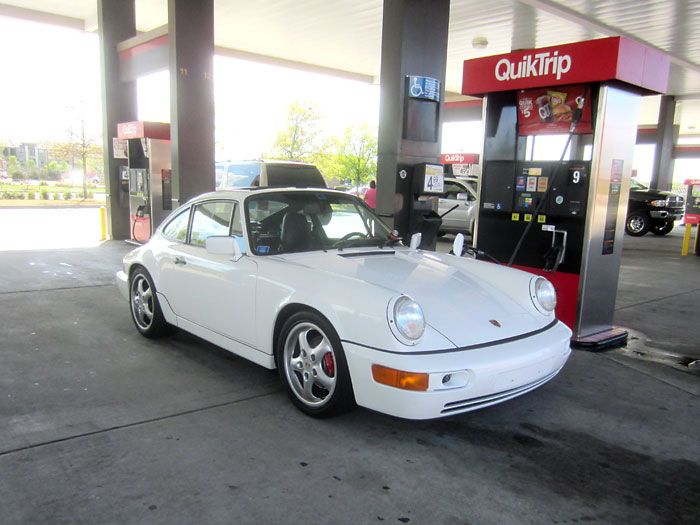
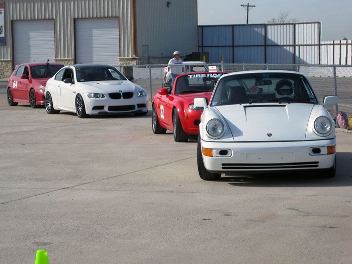
Since I got my car back in 2011, I knew getting it lowered and sitting right was on my to-do list.
After I did a few autocrosses and the car drove like a hot mess, it was definitely a top priority to get suspension sorted.
So I started to accumulate parts here and there, new, used, and unused, as they became available.
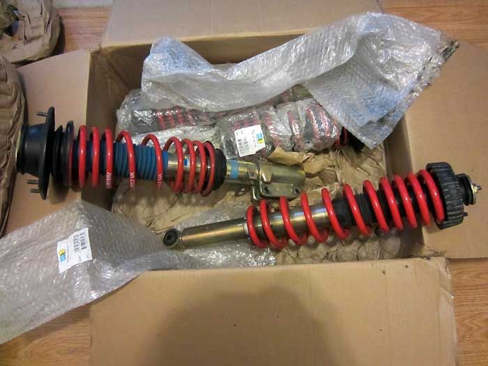
A like-new set of H&R Turbo �Red� springs and Bilstein HDs for less than $1k
Brand new set of ERP spring plates on eBay for $400 (normally $800), a Rennline strut bar for cheap from some guy who never got around to install it, etc.
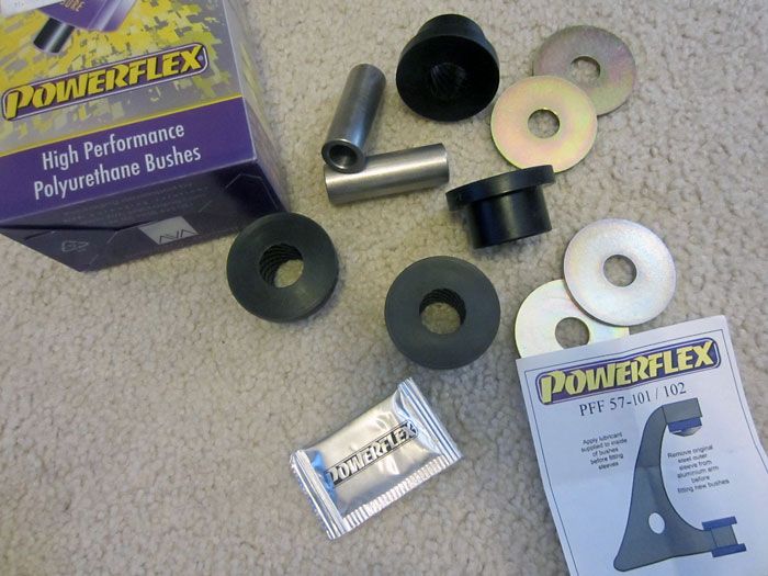
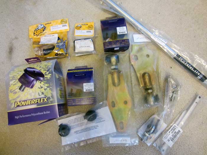
Powerflex bushings for all arms
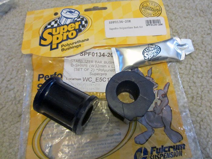
SuperPro bushings for the swaybars
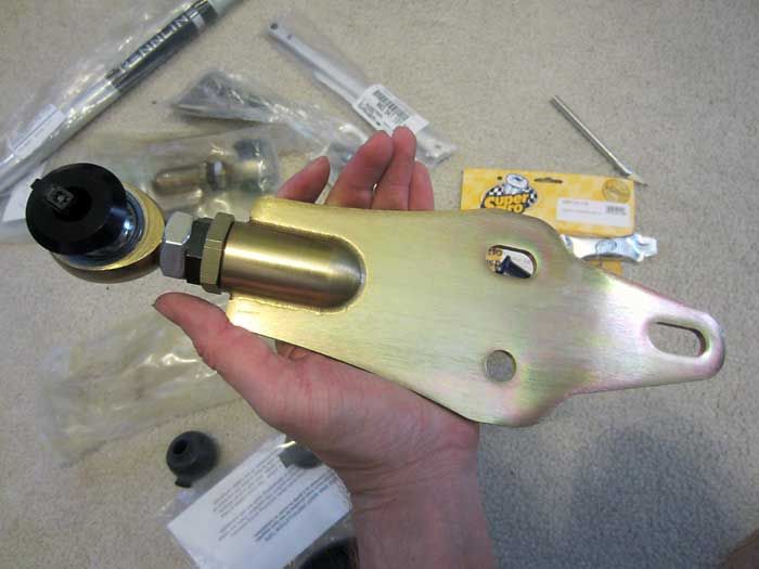
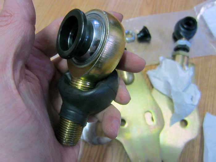
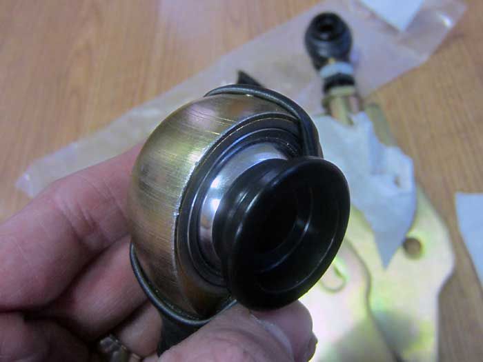
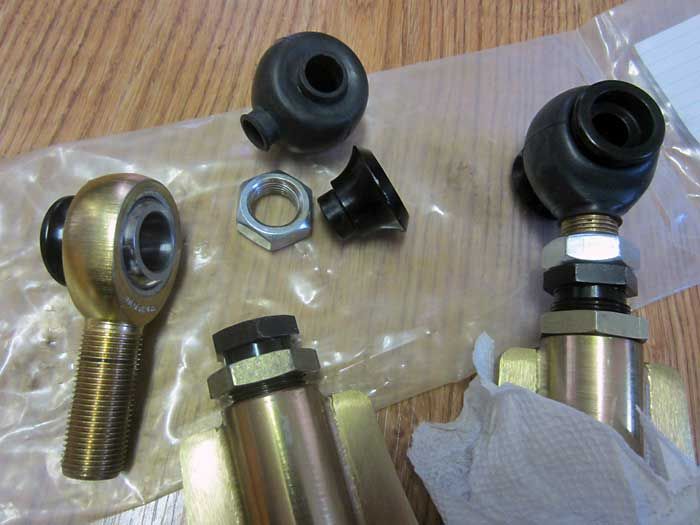
ERP 935-style rear spring plates
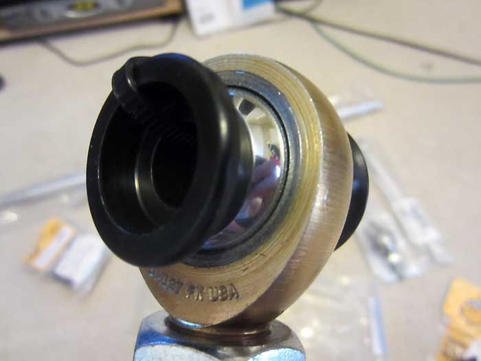
Close-up of the spherical bearing end
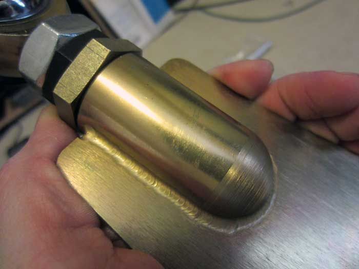
Plate construction
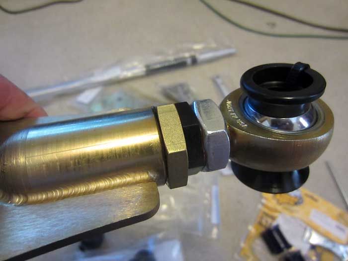
Toe adjustment via tie-rod like assembly
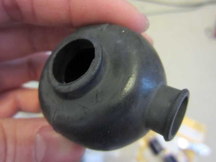
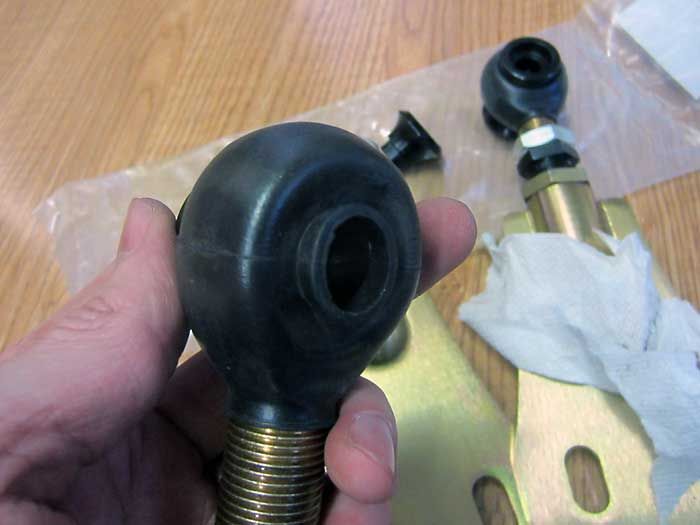
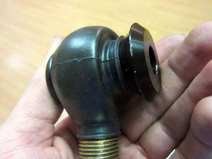
Rod-end boots to help with spherical bearing longevity
Installation, total PITA
Almost there.
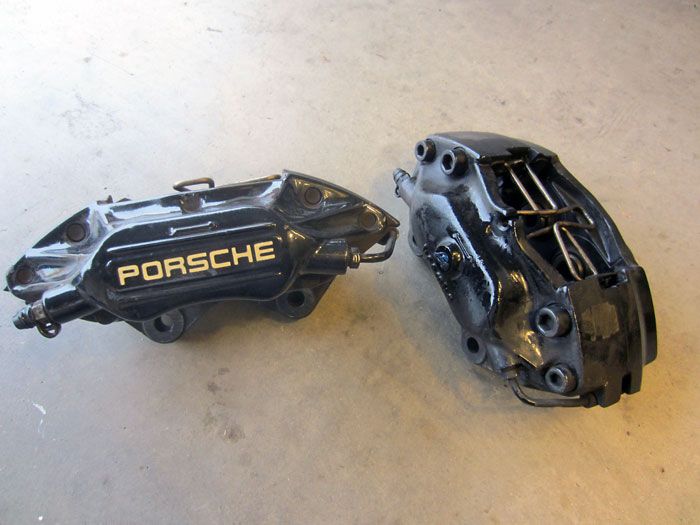
I also sourced some 4-piston rear calipers
Compared to the 2-piston units that were standard on C2s through �91.
Around December 2012, I finally had all my parts together
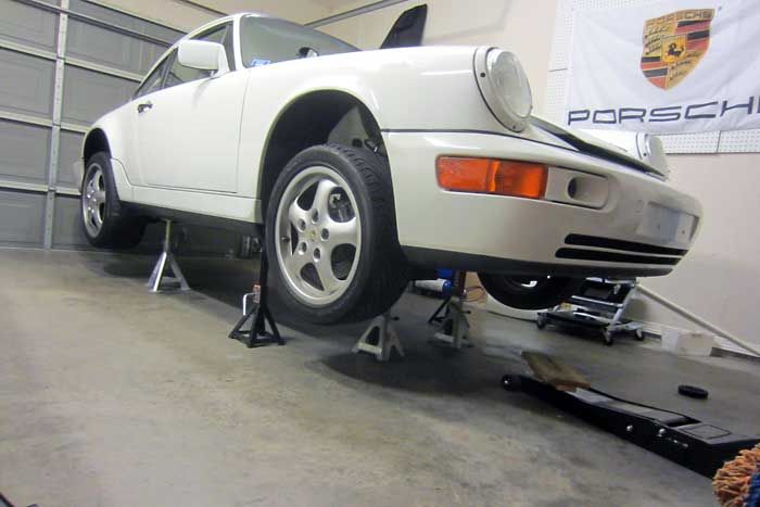
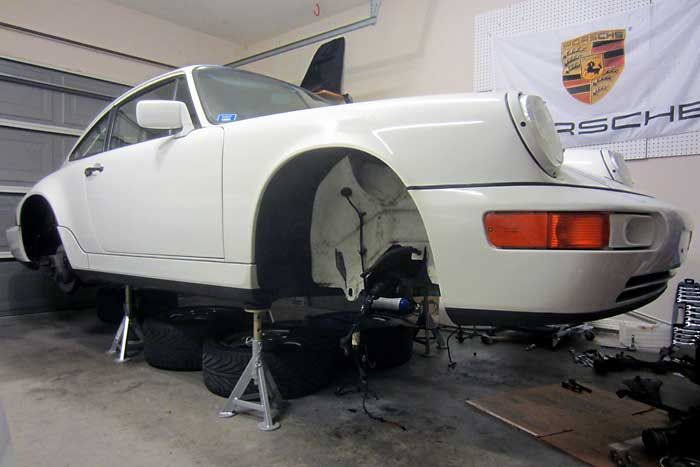
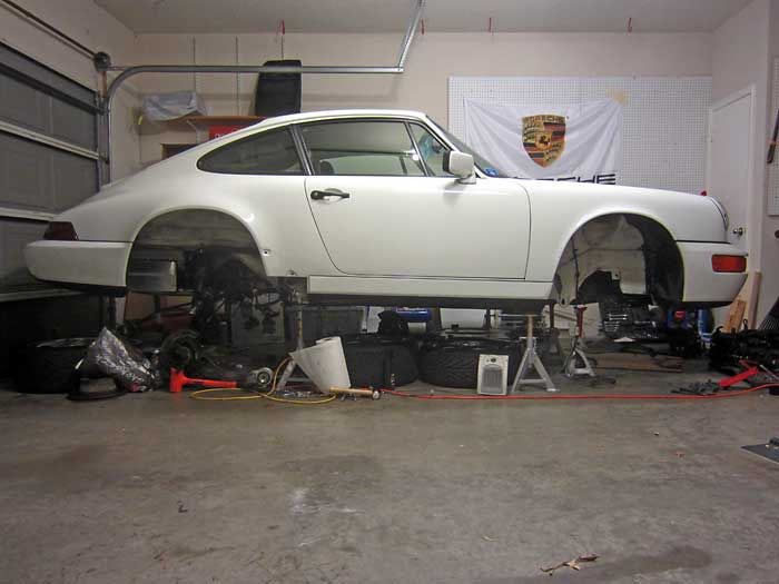
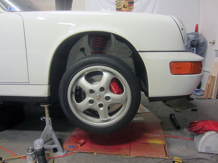
All jacked up.

Front caliper out of the way, drigging brake fluid all over the floor.
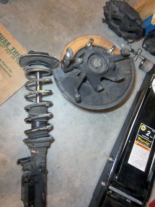
Uprights, struts, off.
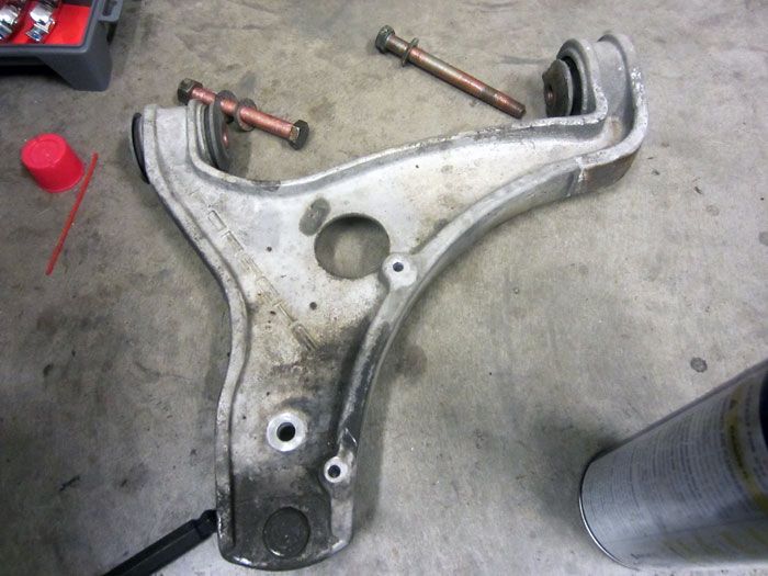
A-arm
Front end all stripped out.
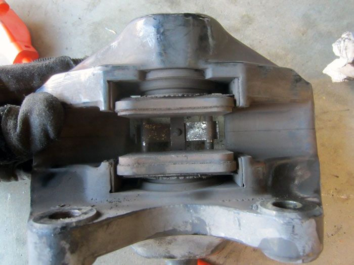
Removed rear calipers, total PITA. Pads were nearly dead.
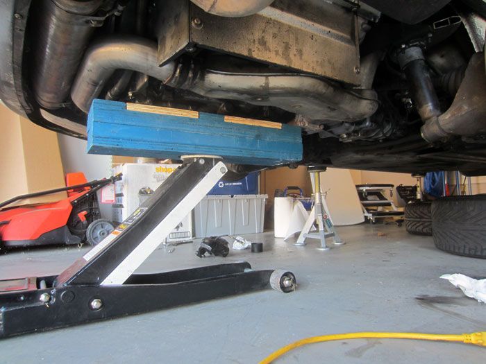
My dad made me these wood blocks for jacking the car from the front tub and also to get extra elevation on the jack stands.
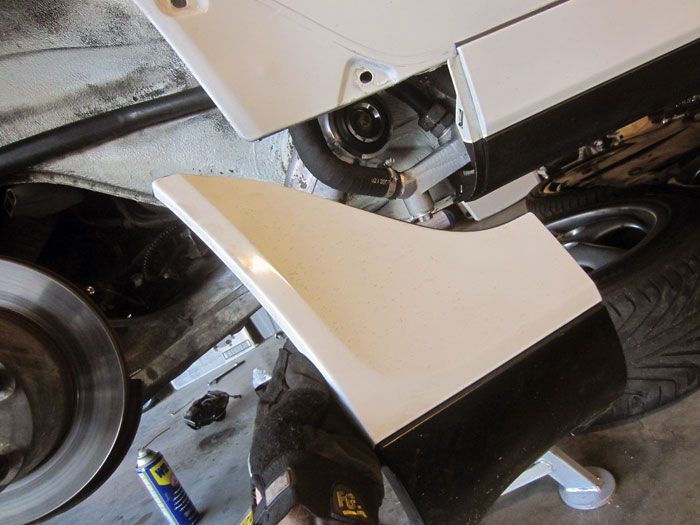
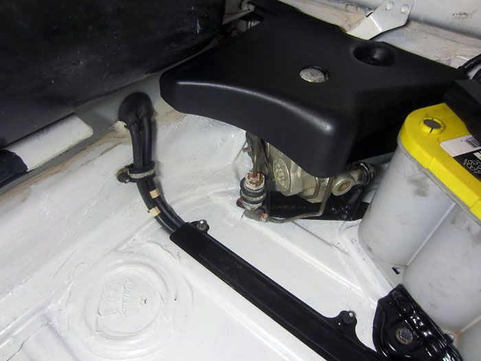
Shark fin needs to come off for access to the trailing arm bolt.
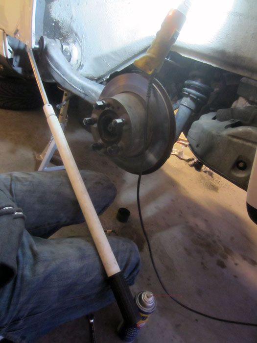
Stupid tight bolts, time to break out the breaker and cheater bars.
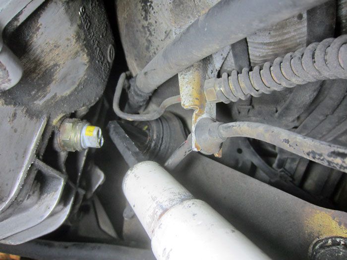
Left (US driver�s side) spring plate bolt, access is not a problem with the breaker bar.
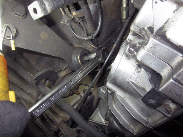
Right (US pass. side) however, transaxle is in the way�
Got pair up a hex key + cheater bar and or spanner to get it off.
Gets it done.
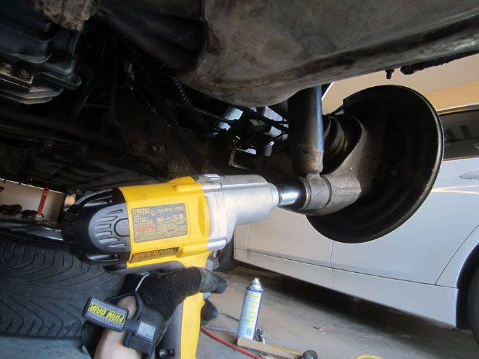
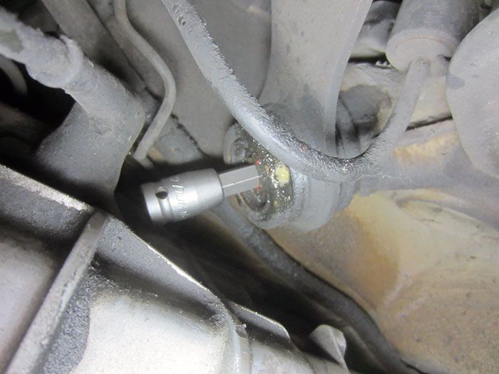
Lower shock bolts are unphased by my 350ft/lb rated electric impact.
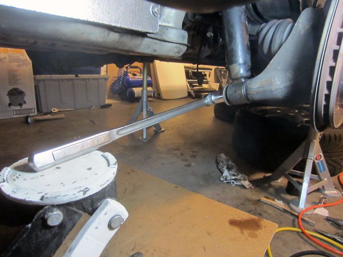
Garage hacks, using the weight of the car plus the floor jack and the breaker bar gets it loose.
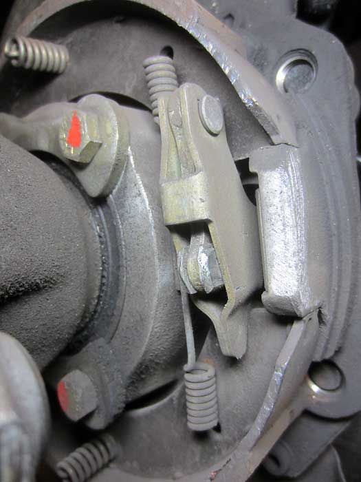
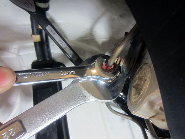
Figuring out how to undo the e-brake w/o disconnecting it from the interior.
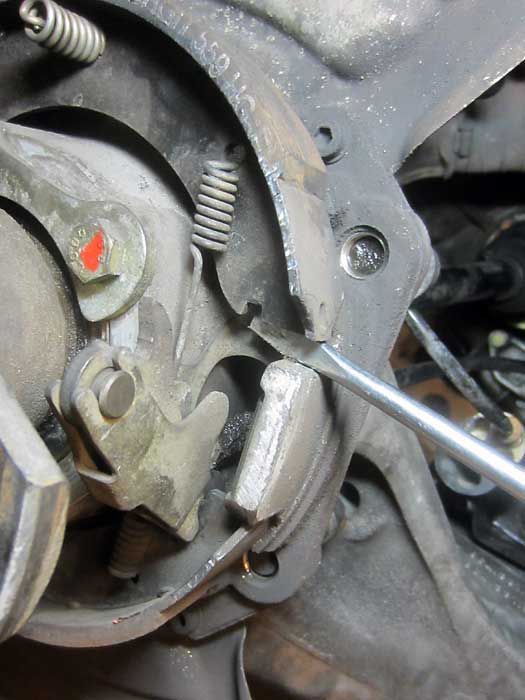
Stick a screwdriver in it, spread it a bit, and the spreader mechanism falls out.
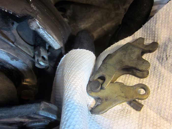
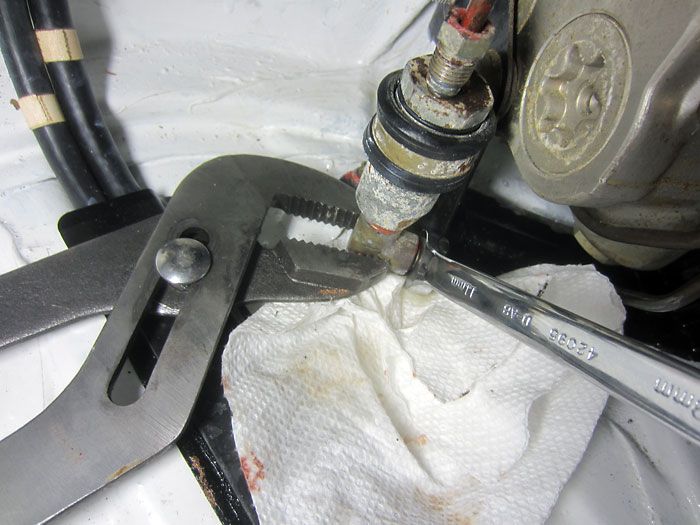
Remember all this for reassembly.
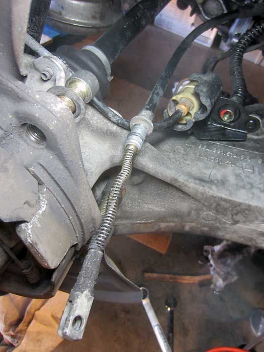
Pull the cable out of the back of the hub, held in by an o-ring.
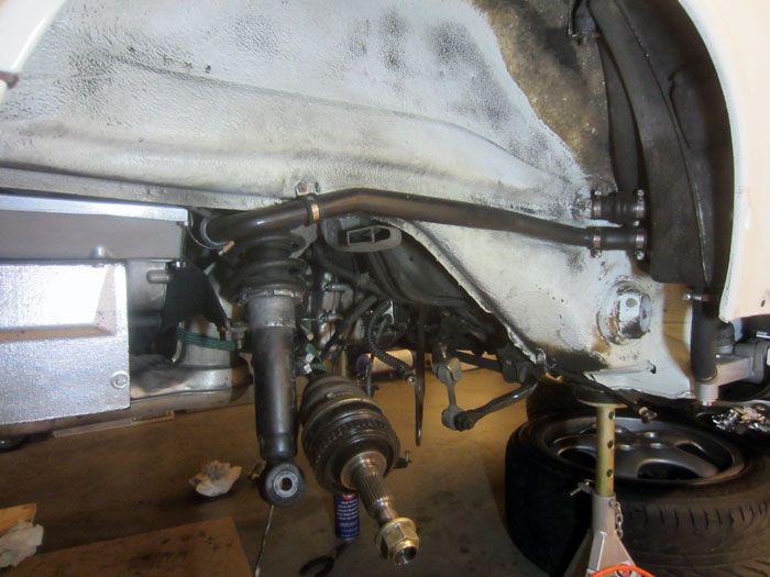
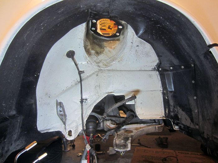
Everything disconnected and you I can drop the whole arm out of the car. I left the axle in place, just used a bungee cord to attach it to the heat exchanger so it didn�t fall down.
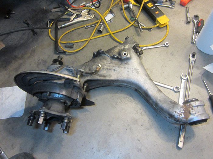
Big lump of aluminum.
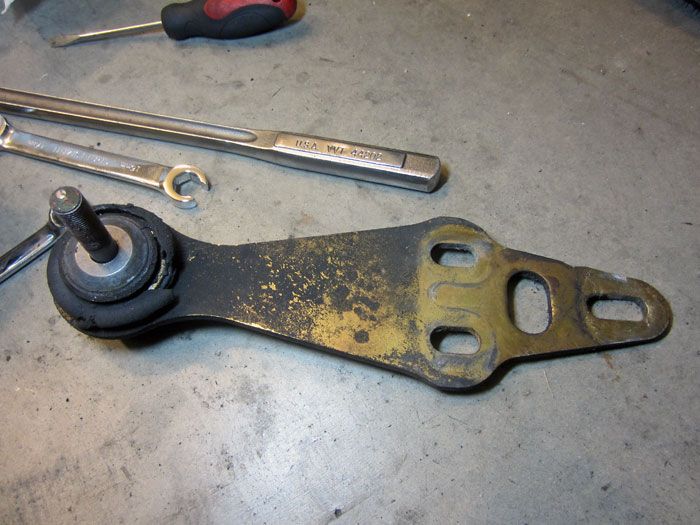
OEM spring plates
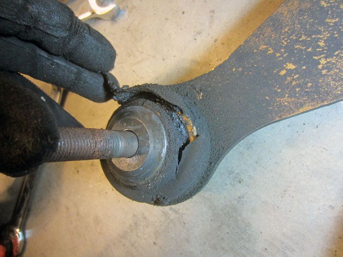
Weissach-effect bushing all busted to ****.
All suspension stripped from the tub.
Shifting attention to the front arms�
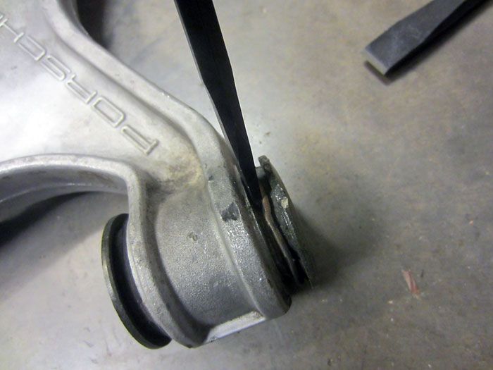
Rearward bushings come out pretty easy, just chisel them out from the flange.
Two per arm.
All out.
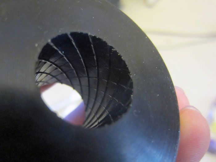
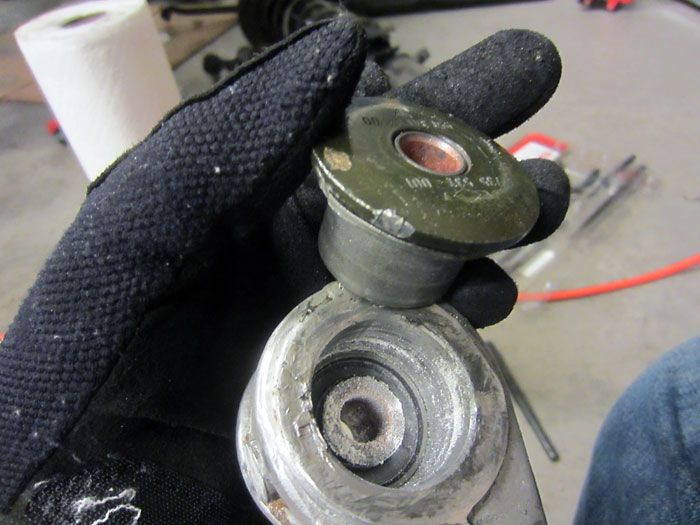
Forward bushing, total PITA. Mine weren�t totally falling apart, but showed some cracks in the rubber when flexed. The bushings yield quite a bit. I suspect they contribute to significant geometry movement for the sake of comfort and compliance.
After I did a few autocrosses and the car drove like a hot mess, it was definitely a top priority to get suspension sorted.
So I started to accumulate parts here and there, new, used, and unused, as they became available.
A like-new set of H&R Turbo �Red� springs and Bilstein HDs for less than $1k
Brand new set of ERP spring plates on eBay for $400 (normally $800), a Rennline strut bar for cheap from some guy who never got around to install it, etc.
Powerflex bushings for all arms
SuperPro bushings for the swaybars
ERP 935-style rear spring plates
Close-up of the spherical bearing end
Plate construction
Toe adjustment via tie-rod like assembly
Rod-end boots to help with spherical bearing longevity
Installation, total PITA
Almost there.
I also sourced some 4-piston rear calipers
Compared to the 2-piston units that were standard on C2s through �91.
Around December 2012, I finally had all my parts together
All jacked up.
Front caliper out of the way, drigging brake fluid all over the floor.
Uprights, struts, off.
A-arm
Front end all stripped out.
Removed rear calipers, total PITA. Pads were nearly dead.
My dad made me these wood blocks for jacking the car from the front tub and also to get extra elevation on the jack stands.
Shark fin needs to come off for access to the trailing arm bolt.
Stupid tight bolts, time to break out the breaker and cheater bars.
Left (US driver�s side) spring plate bolt, access is not a problem with the breaker bar.
Right (US pass. side) however, transaxle is in the way�
Got pair up a hex key + cheater bar and or spanner to get it off.
Gets it done.
Lower shock bolts are unphased by my 350ft/lb rated electric impact.
Garage hacks, using the weight of the car plus the floor jack and the breaker bar gets it loose.
Figuring out how to undo the e-brake w/o disconnecting it from the interior.
Stick a screwdriver in it, spread it a bit, and the spreader mechanism falls out.
Remember all this for reassembly.
Pull the cable out of the back of the hub, held in by an o-ring.
Everything disconnected and you I can drop the whole arm out of the car. I left the axle in place, just used a bungee cord to attach it to the heat exchanger so it didn�t fall down.
Big lump of aluminum.
OEM spring plates
Weissach-effect bushing all busted to ****.
All suspension stripped from the tub.
Shifting attention to the front arms�
Rearward bushings come out pretty easy, just chisel them out from the flange.
Two per arm.
All out.
Forward bushing, total PITA. Mine weren�t totally falling apart, but showed some cracks in the rubber when flexed. The bushings yield quite a bit. I suspect they contribute to significant geometry movement for the sake of comfort and compliance.
 06-01-2014, 12:24 AM
#2
Nordschleife Master
Thread Starter
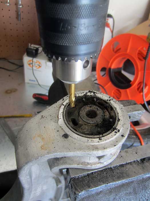
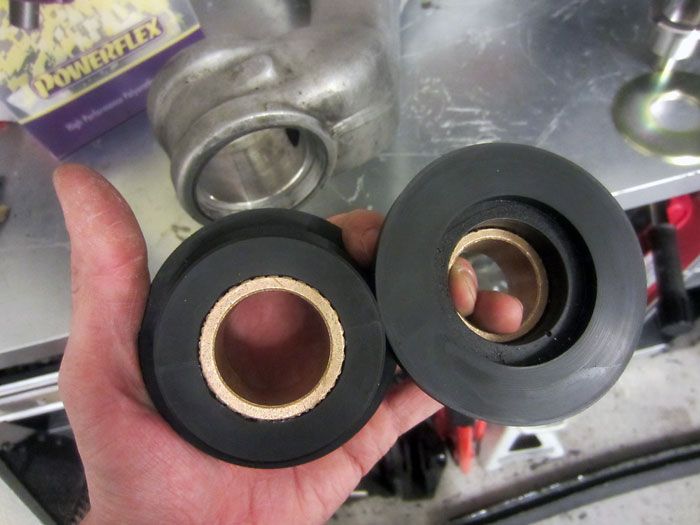
Try to drill around the perimeter so that the bit goes between the rubber and metal sleeve. The idea here should be that you want to separate the rubber from the metal sleeve.
Notice how the rubber part stayed mostly intact and attached to the center piece. That’s what you want.
If the separating the rubber from the metal sleeve went well above, then you should have some nice area to saw at. This makes your life so much easier.
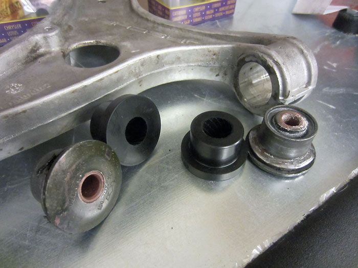
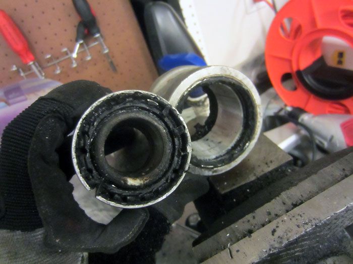
Bushing on the left was my first one, and you can see how the rubber broke apart and made cutting into the sleeve a vague PITA. I was there messing w/ it for hours. The center bushing went much better and literally took me 30 mins. The right is the Powerflex bushing. Notice how the Powerflex comes with its own hardware, no need to clean the old rubber off of the old center or reuse that piece.

Arms all cleaned up.
Powerflex piece on lead bushing position
Unlike other front A-arm bushing options, the Powerflex come with new hardware. Notice how the right (original) piece has a key on it.
That key locks into the front subframe in order to keep the piece from spinning and allowing you to properly torque the fastener.
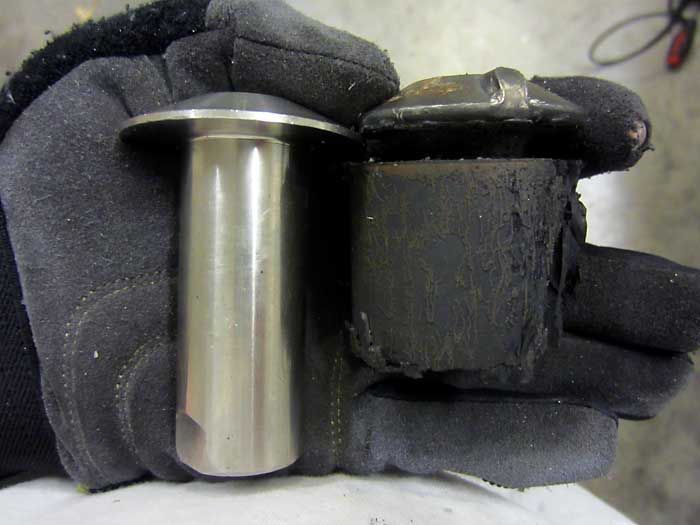
Unlike the OEM piece, the Powerflex piece has a longer nose and some flat spots on it.
This lets you put a wrench on the piece and hold it stationary while you torque the lead fastener.
Sleeve and bushing all greased up.
Rearward bushing hardware, just a metal sleeve and a pair of washers.
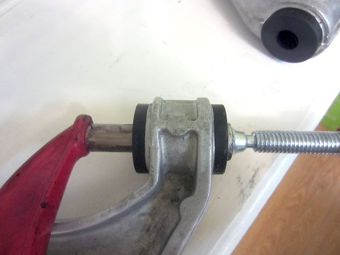
Using a big C-clamp to push the greased metal sleeve through the two-piece rear bushing
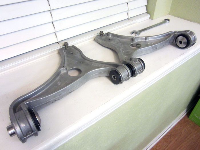
Front arms all done, ready to go back on the car.
More info on the front Powerflex bushings and installation here.
https://rennlist.com/forums/964-foru...-bushes-2.html
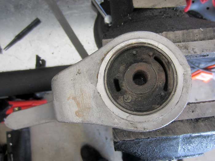
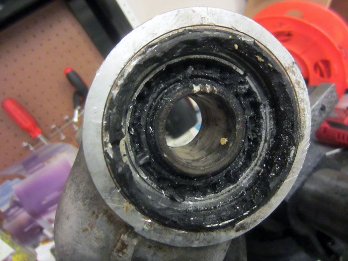
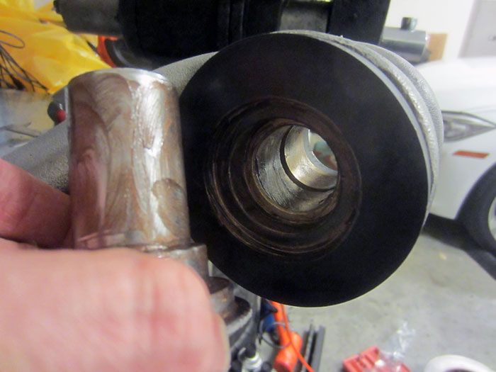
Moving on to the rear trailing arms
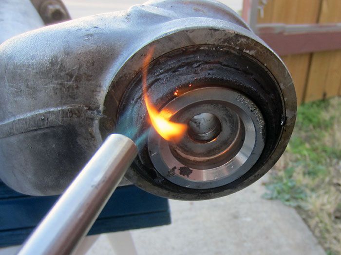
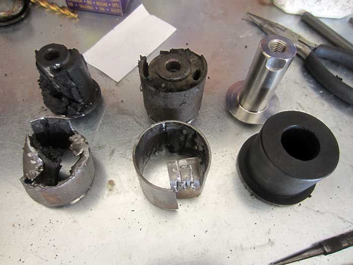
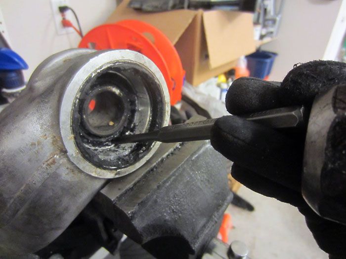
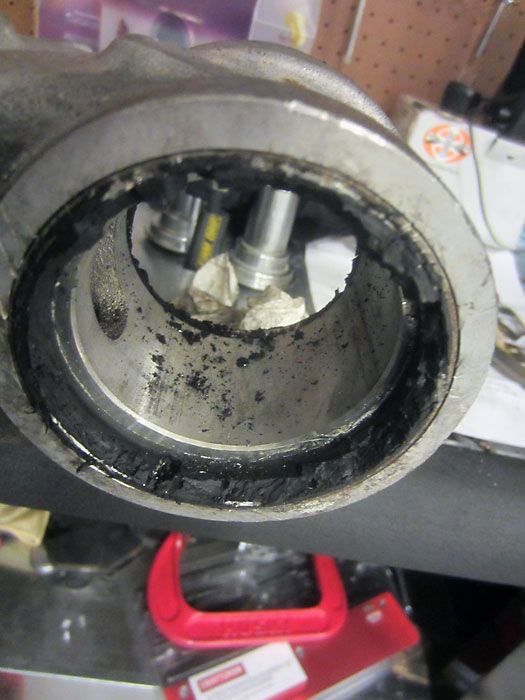
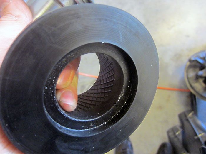
Start by taking a box cutter to the circumference of the rubber bushing and then hitting it w/ a torch.
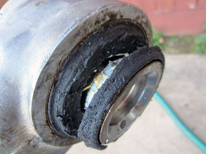
After some heat, use a large flat screwdriver to start prying out the center.
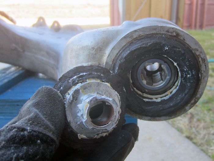
It comes out eventually. You will not reuse this piece.

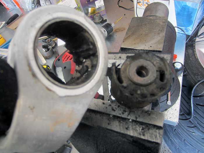
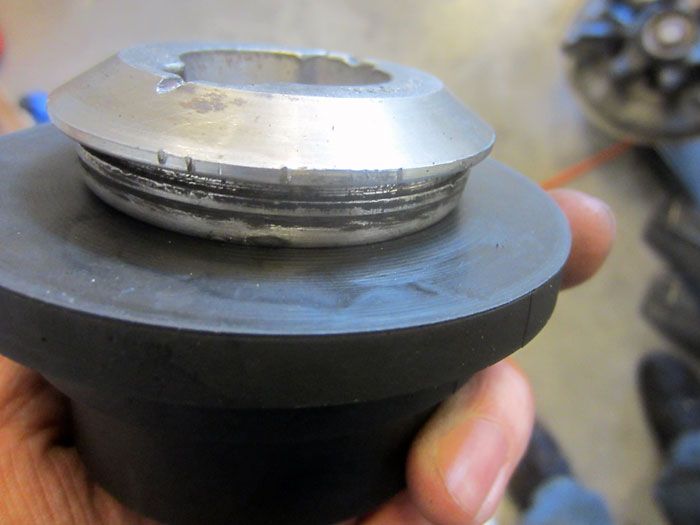
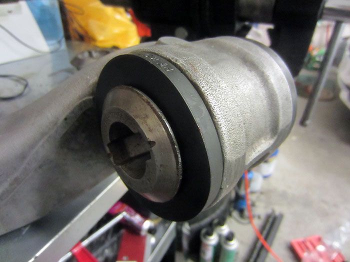
Proceed with the backside of the bushing. Once again, cut the rubber w/ a blade and apply heat.
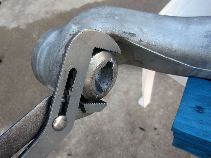
Using some Channel-lock pliers, work it back and forth and pry w/ a flat screwdriver.
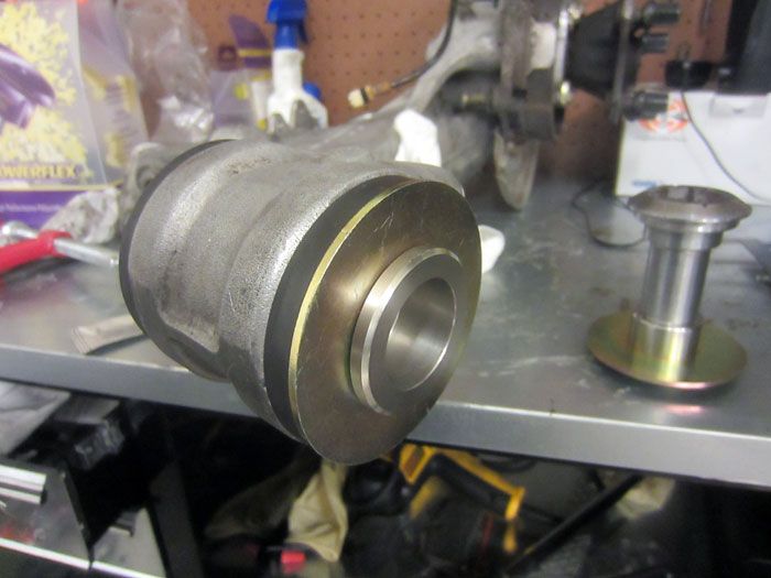
It’ll come out eventually. Remember, you’re going to have to reuse this piece (backside metal center of the OEM bushing).
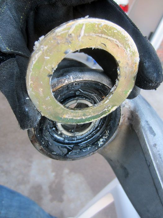
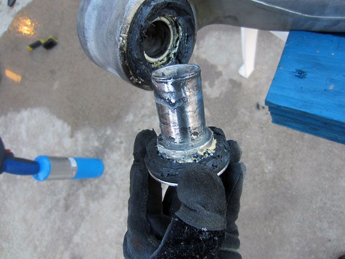
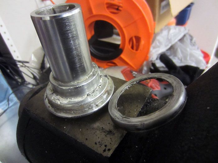
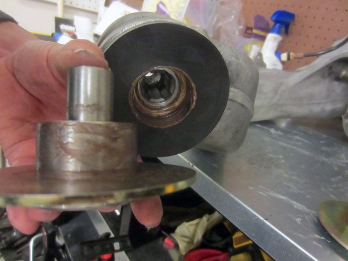
Behind the main pieces there are large embedded washers in the rubber assembly.
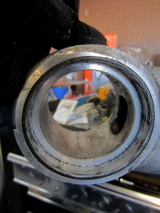
So now you’re left with just the inner structure.
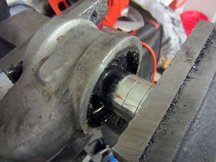
Using a large socket and a vise, it’s pretty easy to push out that center.
A little punch action gets it all the way out.
All out.
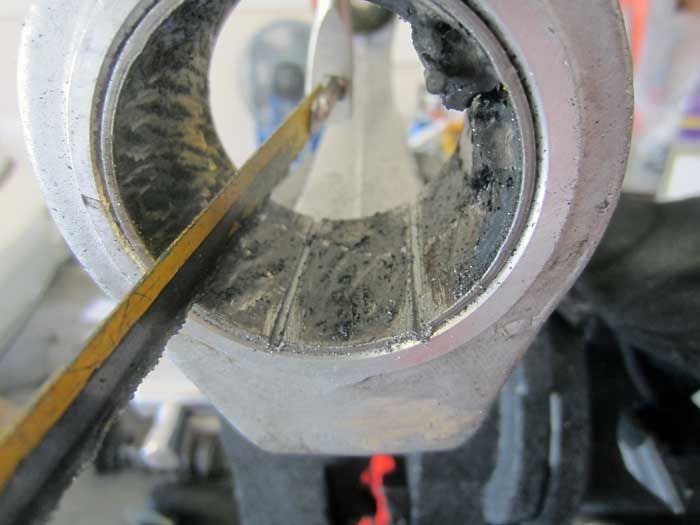
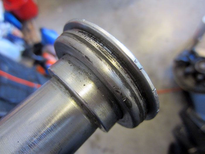
You’re left with this, a bunch of rubber stuck to the outside edges.
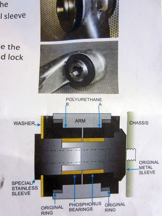
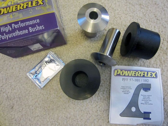
Now you gotta pay attention to the Powerflex diagram. Unlike a monoball installation, the Powerflex kit requires you to keep the OEM outside ring intact.
After much rubber cutting and scrapping with a sharp blade, you’re left with a clean arm and the OEM ring intact. Ready for the Powerflex pieces.
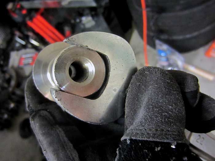
Remember that center piece you’re going to reuse from the OEM assembly?
It goes here.
But not quite.
Gotta pop off this extra ring piece, now you’re set.
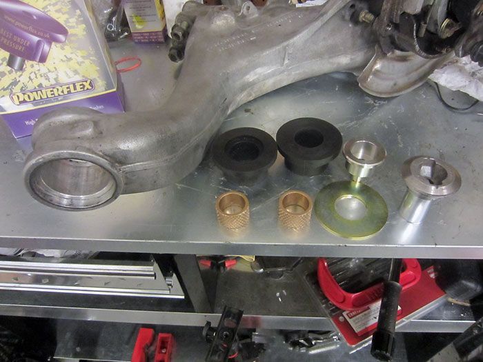
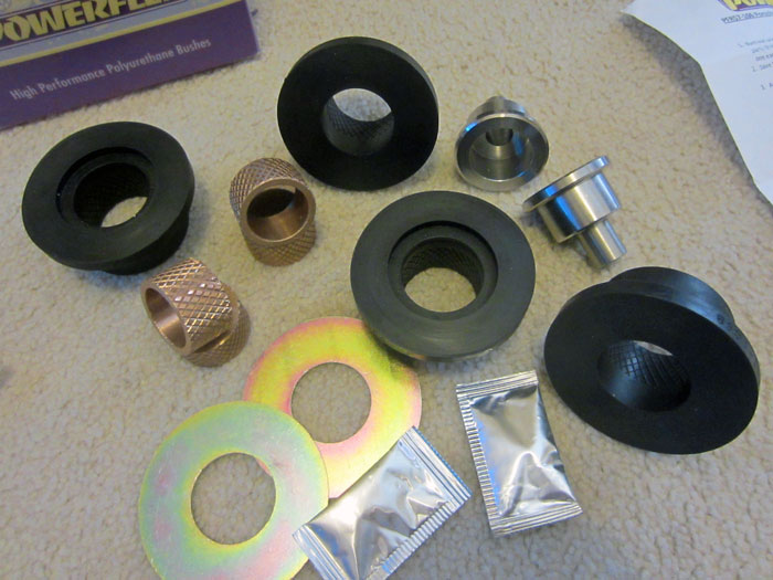
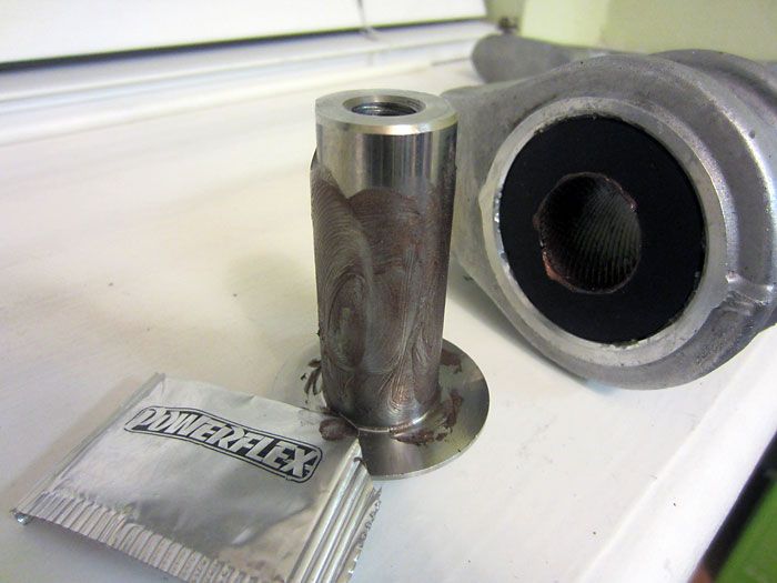
All the parts on the table.
Powerflex phosphorous bearings inserted into the poly bushing assembly.
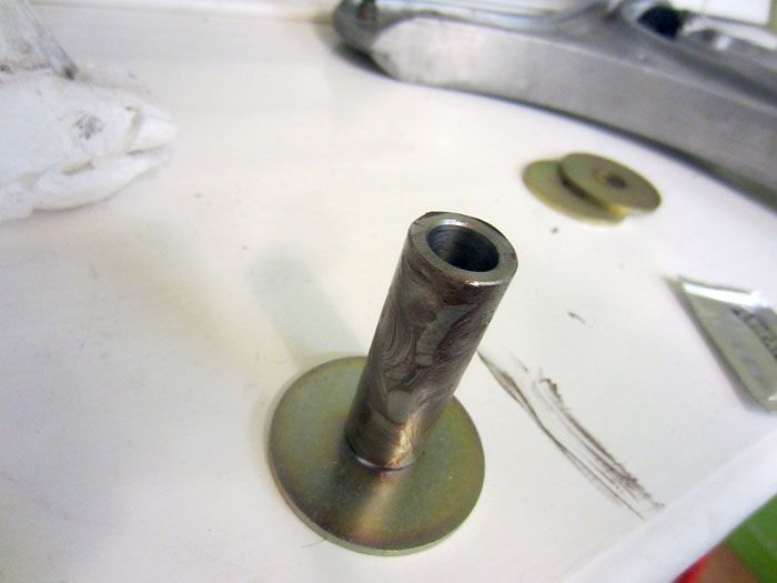
Bushings inserted into the arm and the reused OEM center piece all greased up.
Backside of the bushing all set.
Front side of the bushing pieces, metal center piece and large washer are all part of the Powerflex kit.
All set, repeat on other arm.
These rear trailing arm Powerflex bushings were developed by Powerflex and NineMeister. You can read more about that here.
https://rennlist.com/forums/964-foru...rm-bushes.html
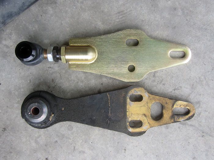
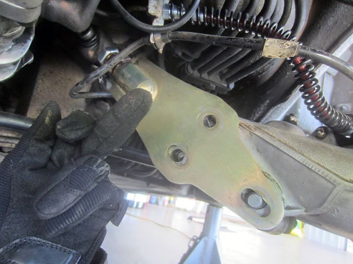
Old and busted spring plate versus the ERP monoball 935-style unit. The OEM pieces adjust toe and camber via two eccentrics. The aftermarket piece adjusts toe via the tie-rod type assembly and camber via the eccentric. Orientation of the slotted hole is key, more on that in a moment.
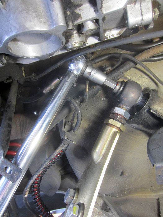
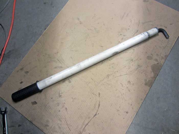
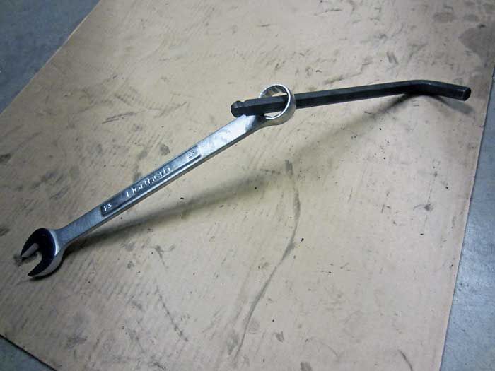
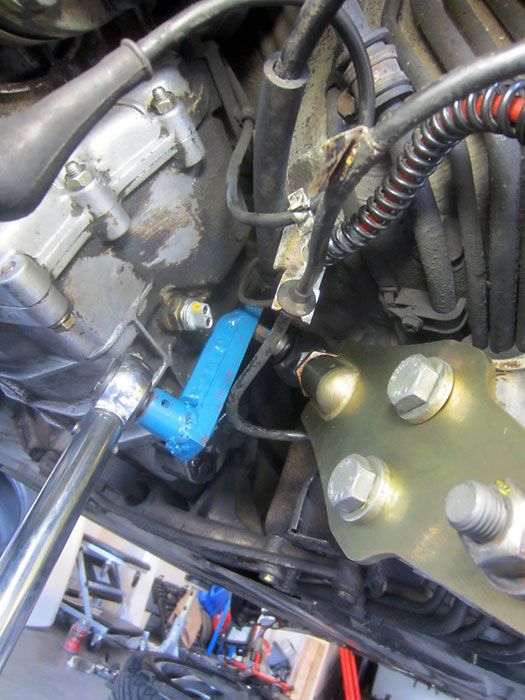
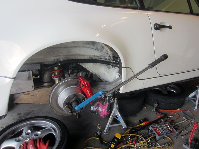
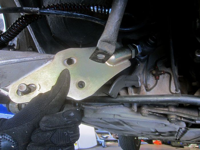
As you remember from the disassembly portion of this thread, the left side spring plate is pretty straight forward access w/ a hex bit and breaker bar.
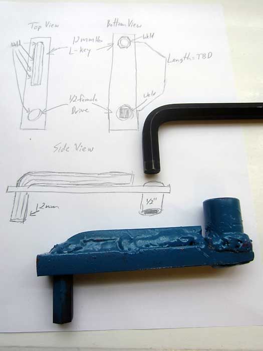
So I made a quick sketch and sent it to my dad and asked him if he could weld together a 12MM hex key and a 1/2" drive custom tool.
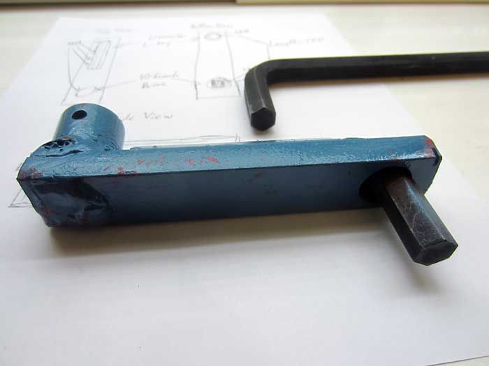
12MM
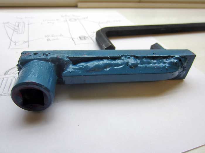
1/2" Drive
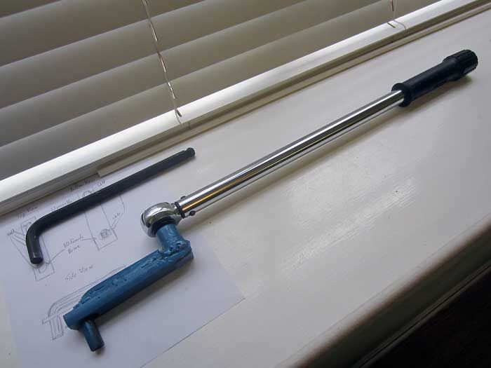
Paired w/ my 250ft/lbs Craftman torque wrench.
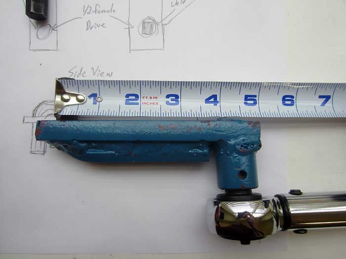
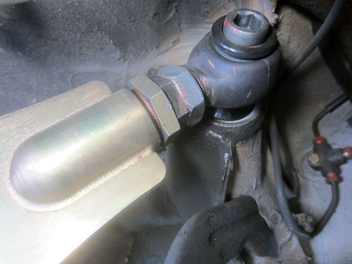
Gotta measure the length of the extension. This is critical since the extension acts as a torque multiplier and that means that I need to back off the torque on my wrench in order to achieve the desired effective torque of 147ft/lbs that this fastener requires.
Plugging in the data points into this online calculator allowed me to get my settings right in order to get the desired torque output.
http://www.freeinfostuff.com/TorqueE...eExtension.htm
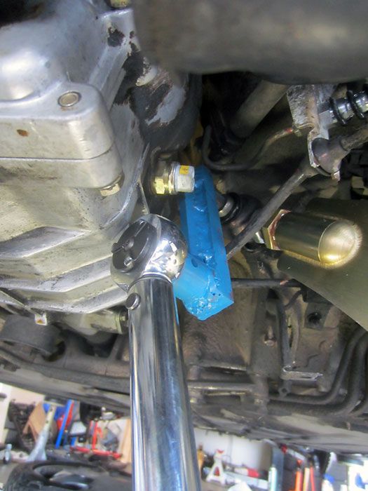
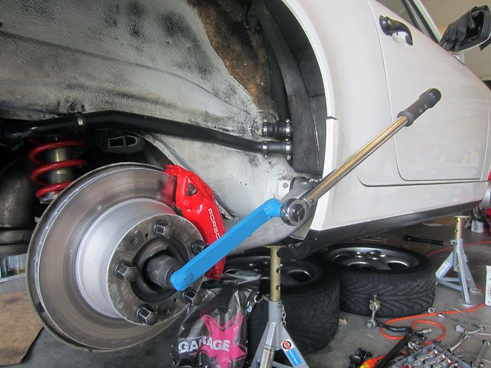
Putting the extension to use.
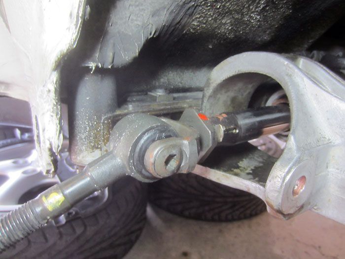
Turning my attention to this, steering stop spacers.
Here’s a good DIY to follow.
https://rennlist.com/forums/964-1989...p-install.html
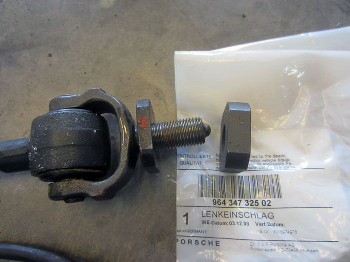
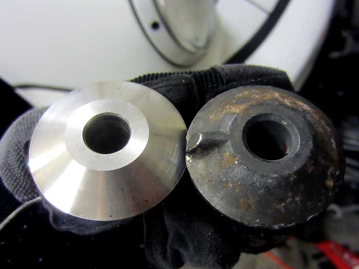
Old steering stop vs the updated thicker (and overpriced, sold individually) stop
All installed, just reinstall the boot.
Last edited by Vandit; 06-01-2014 at 09:58 AM.
06-01-2014, 12:24 AM
#3
Nordschleife Master
Thread Starter
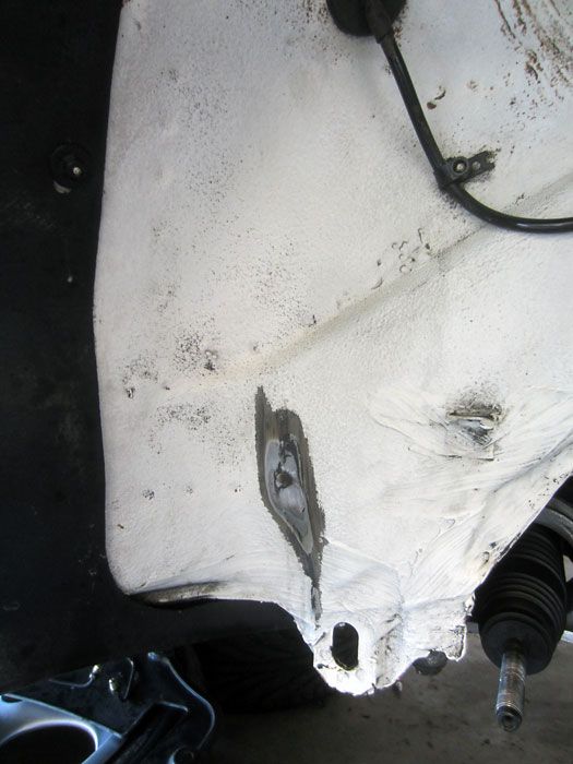
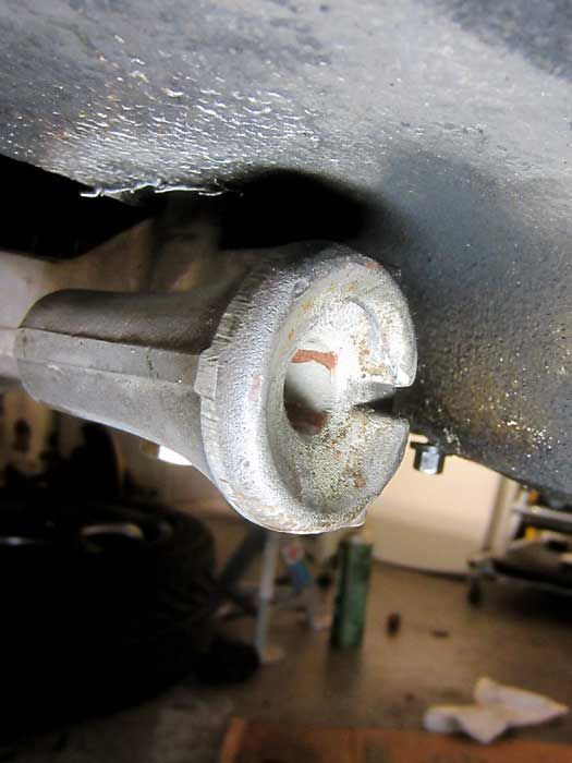
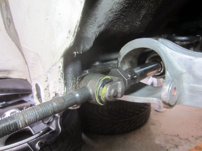
Here’s the situation I was trying to improve with the thicker steering stops.
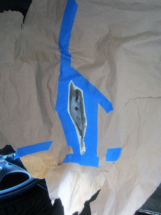
Taped up and prepped
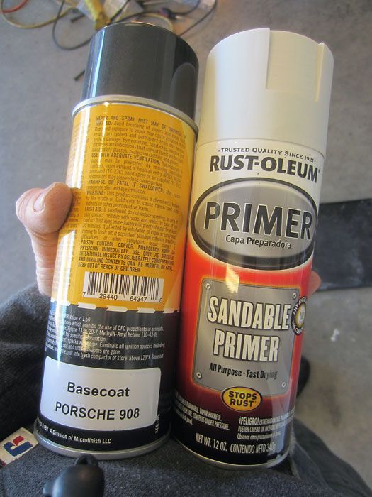
GP White basecoat from Automotvetouchup.com and some primer
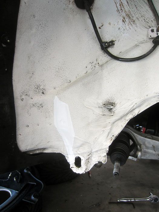
Good enough result, but will become a moot point later.
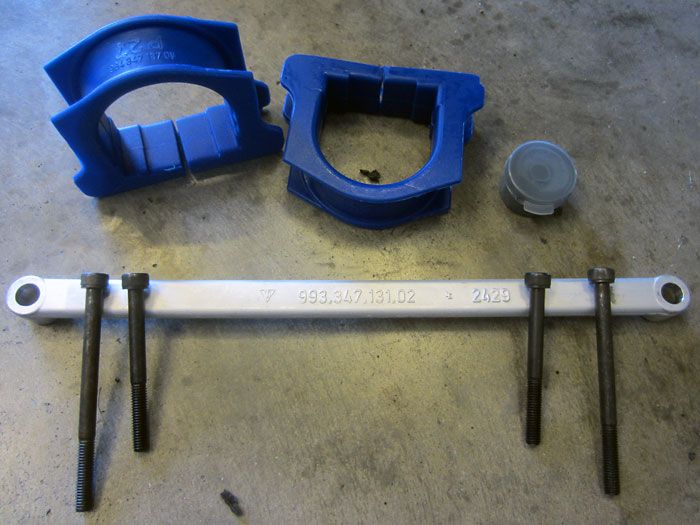
Moving along to the rack area. Poly bushings I got off of ebay and the 993 rack brace.
I know plenty folks say this brace doesn’t fit on a 964, but Marc Shaw’s post convinced me to give it a shot.
https://rennlist.com/forums/9040606-post45.html
In order to install the 993 brace, you need a couple of longer fasteners, and it is recommended to not reuse these fasteners. The 4 bolts you need are two M8, 1.25 thread, 60mm length and two M8, 1.25 thread, 80mm length. The OEM bolts are grade 10.9 so don't go any lower. The ones Fastenal sells are 12.9.
The jury is still out on the poly rack bushings… I know a few others on the board (including 993 subforum) run them too.
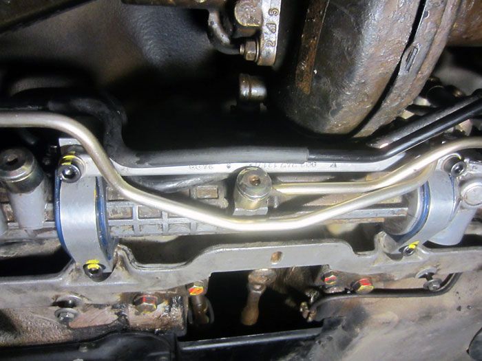
All buttoned up and installed.
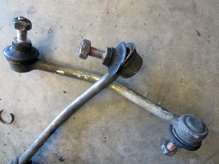
My front drop link boots were all torn up.
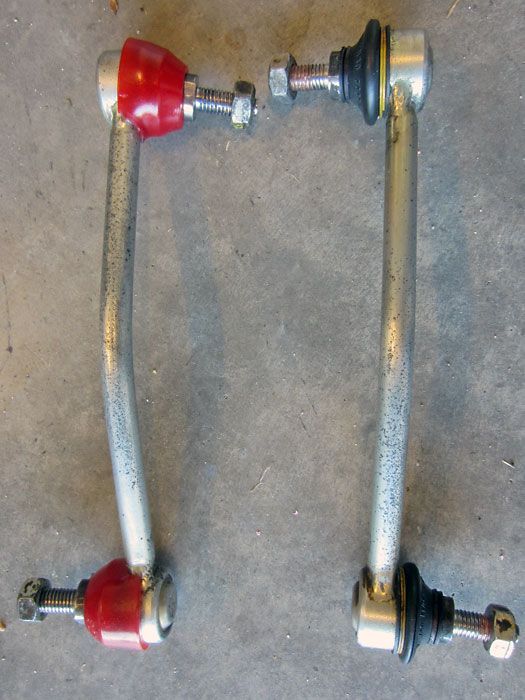
I refurb’d them using some boots from Energy Suspension.
Read more on the topic of replacing droplink boots here.
https://rennlist.com/forums/964-foru...bar-links.html
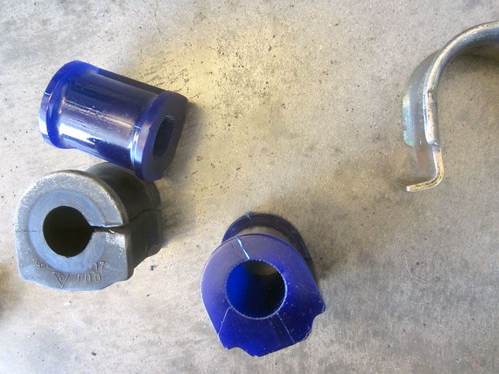
I went with SuperPro poly swaybar bushings throughout, they were cheaper than Powerflex units.
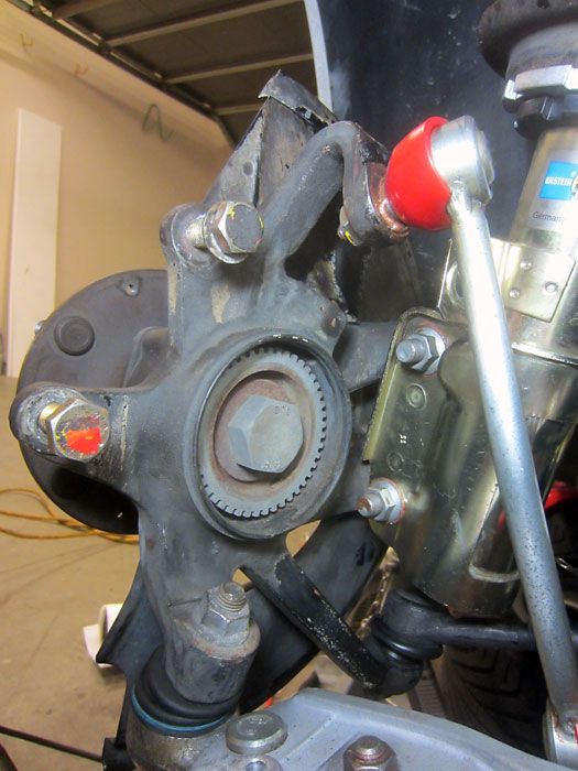
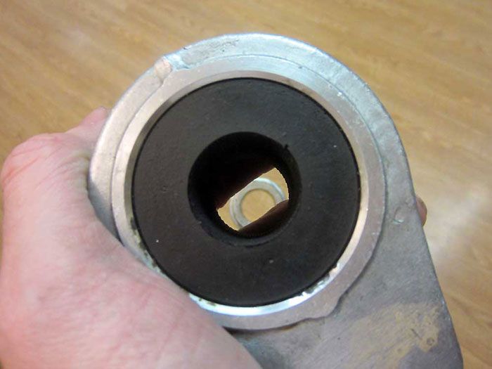
I’m not sure why earlier model 964s don’t have a cap on the rear of the wheel carriers.
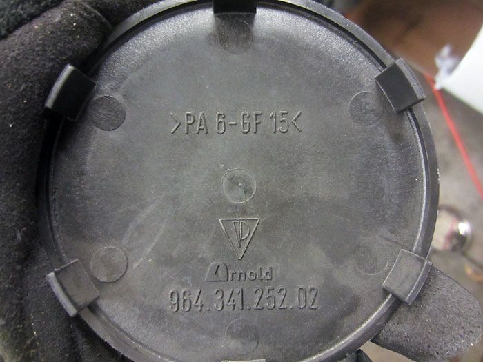
Ordered the caps, 964.341.252.02
They fit just fine.
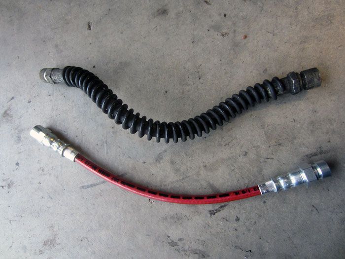
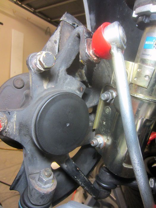
ECS Tuning Exact-Fit brake lines throughout.
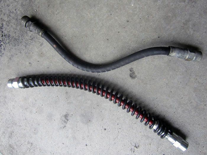
Transferred the coil-like protectors from the 22yo lines to the new lines.
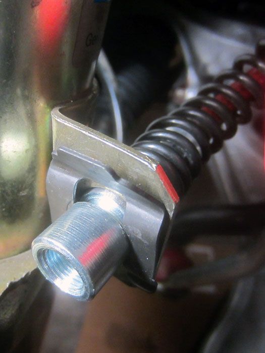
Fresh retaining clips and what not.
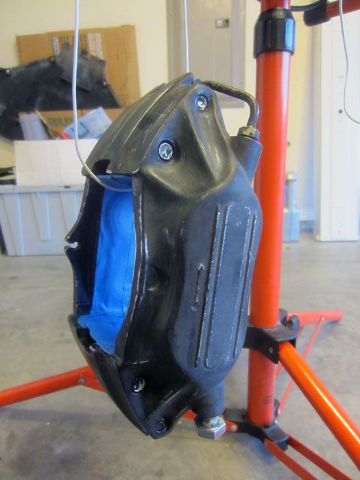
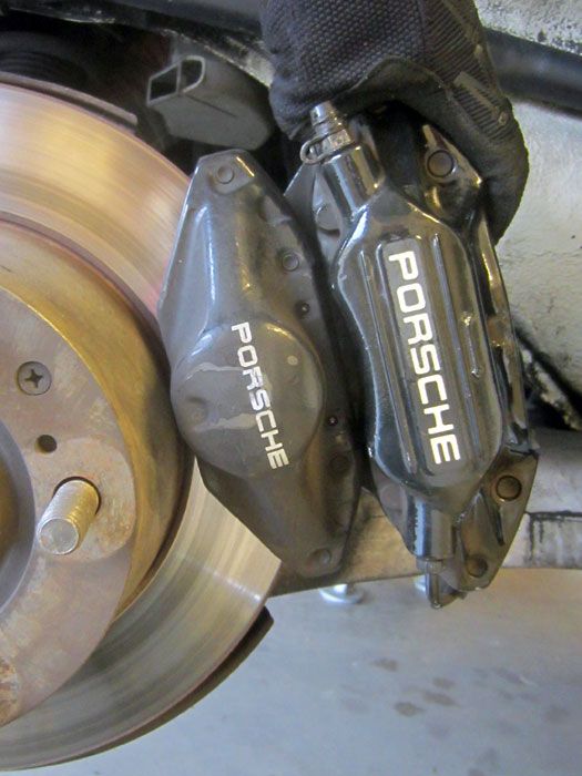
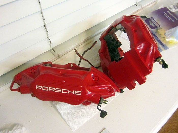
Decided to spruce up my old calipers. This was after brake cleaner, degreaser, wire brush, sanding, chemical paint stripper, etc.
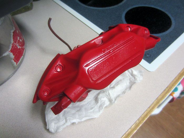
I decided to use VHT red caliper paint.
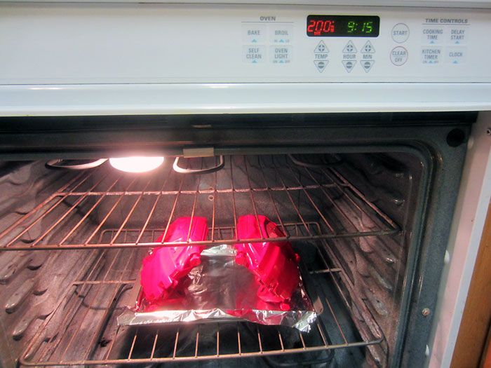
After a decent set of base color coats, it goes in the oven for 1 hour at 200 fahrenheit to set the paint.
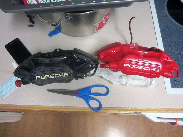
Applied decals I got off of ebay.
After the decal, several coats of VHT clear coat and back in the over to set the paint.
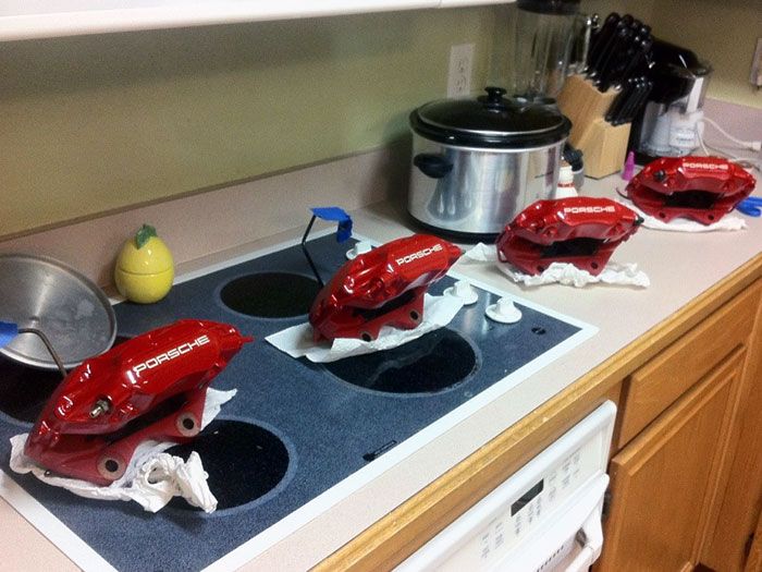
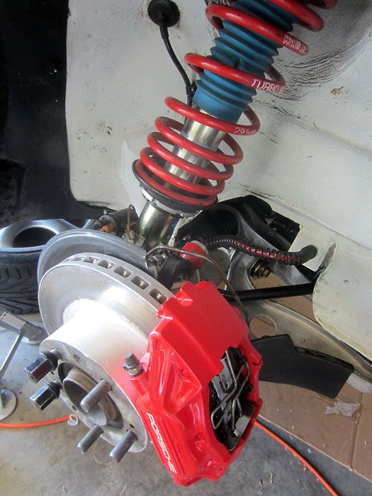
Calipers all pretty.
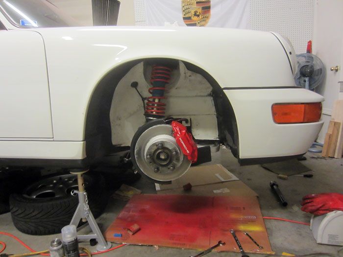
Coming back together.
Shining through my Cup 2 wheels.
Since my car was originally equipped with the smaller rear calipers, leaving the proportioning valve unchanged would mean I’d be under-driving the rear calipers.
On with removing the valve.
A bit of a pain. I don’t want to be bending lines around the ABS pump.
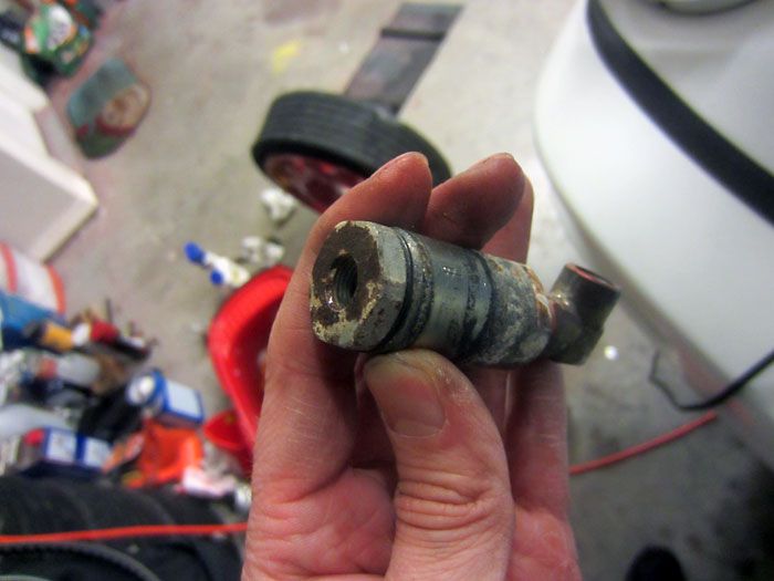
And it’s out.
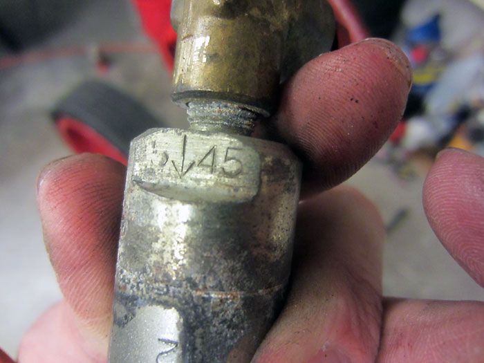
45 BAR. Cars w/ 4-piston calipers from the factory will be equipped with a 55 BAR valve to put more pressure on the rear calipers.
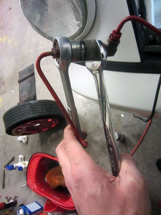
Now the valve is coming apart.
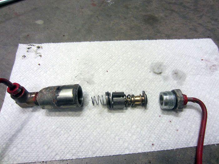
All apart, and all those pieces you see between the halves will be removed. This will put more pressure on the rear than even a 55 BAR valve, but that’s okay for me.
Lots more info on the proportioning valve can be found here.
https://rennlist.com/forums/964-foru...look-like.html
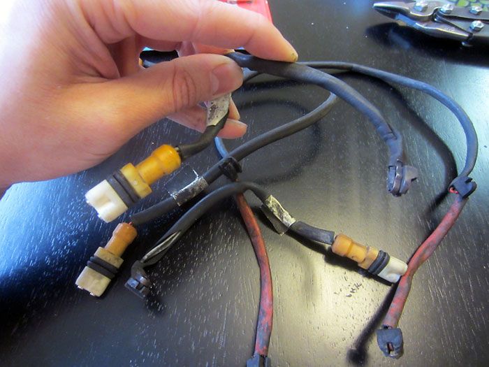
Now on to the brake pad wear sensors. These are one-time use and the idea is, when the brake linings wear past a certain point, the circuit will break and you get a dummy light on the dash letting you know your brake pads are near the end of their life.
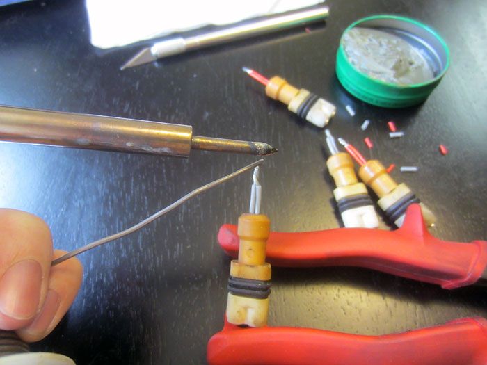
As an enthusiast, I’d like to think I stay abreast of my brakes and don’t need a dummy light, so I cut the sensor wires and permanently close the circuit.
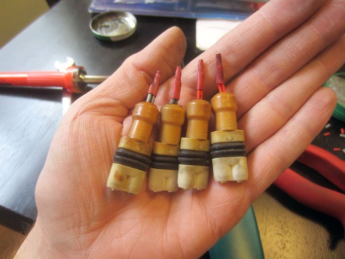
Nice and clean.
Front suspension coming back together.
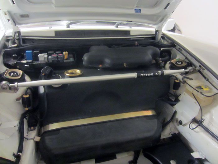
I also picked up a Rennline strut bar. I realize that the positive benefits of the bar are essentially moot since I am still running the rubber OEM top mounts, but still put it on there.
Rear coming back together.
My dad also welded me together a 8” torque extension with a male 1/2" drive on one side and a female 1/2" drive on the other side allowing me to torque the rear axle nut to 339ft/lbs with my 250ft/lbs torque wrench after calculating the applied torque using an online calculator.
http://www.freeinfostuff.com/TorqueE...eExtension.htm
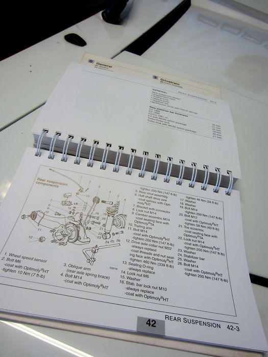
Using the 964 Technical Detail book for torque figures is really helpful for a project like this.
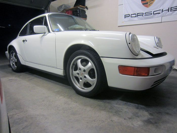
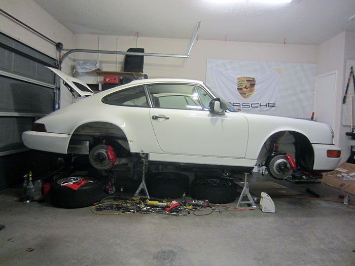
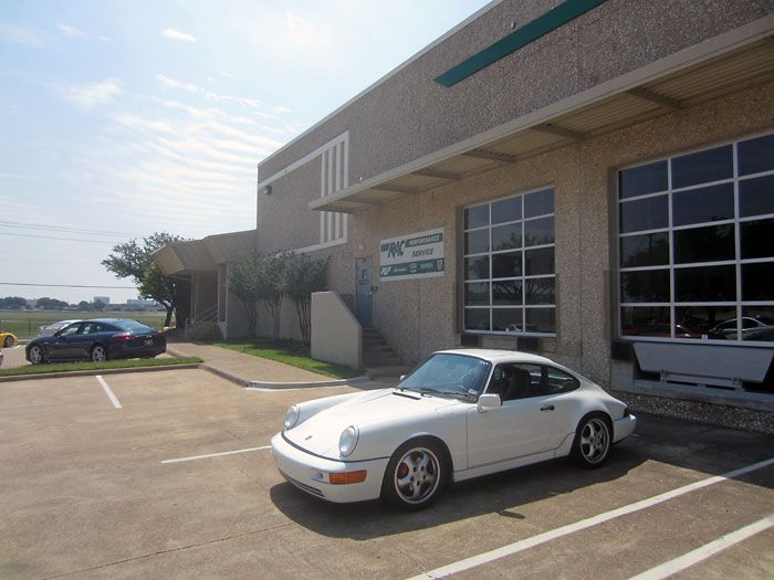
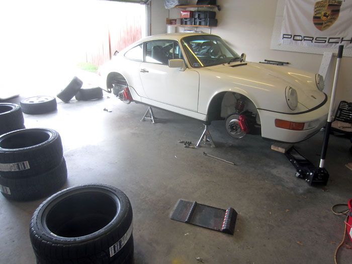
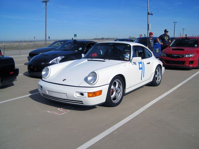
First time out the garage after a long winter hiatus, now with a new ride height.
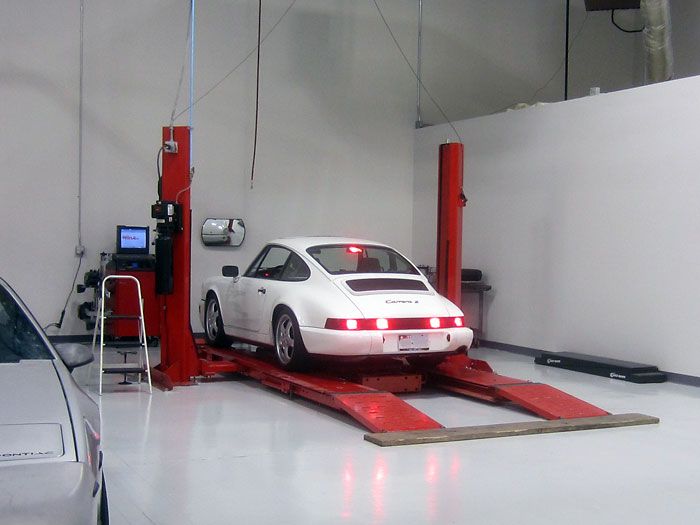
At RAC Performance getting my initial alignment. Check out my 5 brake light mod!
After initial alignment, all done, but disappointed with the result because the rear camber maxed out at -1.2 degrees. Definitely not what I was looking for!
Jam nuts, how do they work??? (Not like this!)
So I went back to scratching me head on why my $800 MSRP 935-style spring plates were giving me a lackluster camber adjustability. I followed the instructions I sourced from Tarett Engineering who sells these plates. It said “Larger camber range, slotted hole to the bottom.”
So after lots of research, and me saying “F it” I figured out that the slotted hole needs to be toward the top in order to achieve more camber adjustment.
Slotted hole to the bottom = small camber range (I maxed at -1.2, very weaksauce).
Slotted hole to the top = large camber range (I maxed at -3.0).
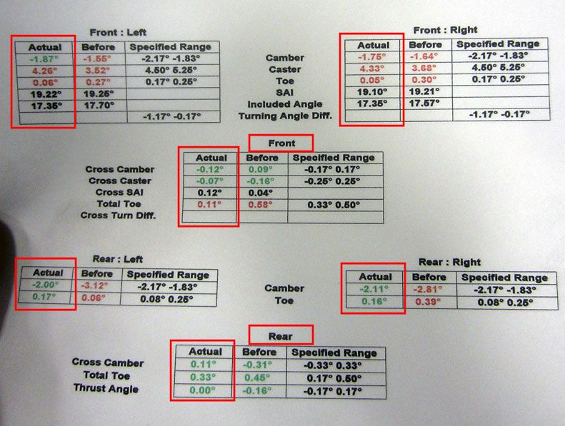
After I flipped the plates, I went back and paid for another alignment, and this time I got a much nicer result.
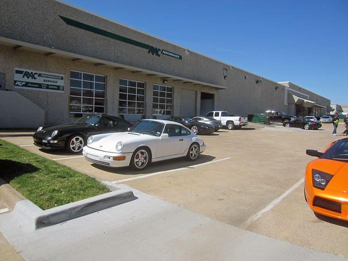
After a much better alignment result. If you’re getting an alignment at RAC Performance, make sure you ask that Seth be the tech doing the alignment. The guy is top notch.
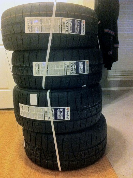
Now that all my tires are pointing and leaning in the right direction, it was time to ditch my dry rotted Pilot Sport PS2s for some real grippy rubber. These new BF Goodrich g-Force Rivals are 200TW and have big tread blocks and big time grip.
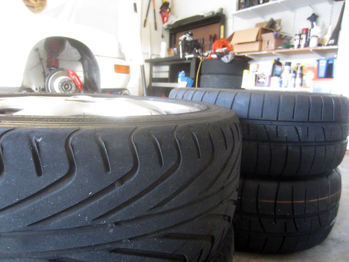
225/45 BFGs vs the 225/45 PS2s. These tires run wide! Meaning now they rub again, even though I installed the updated steering rack stops, lol.
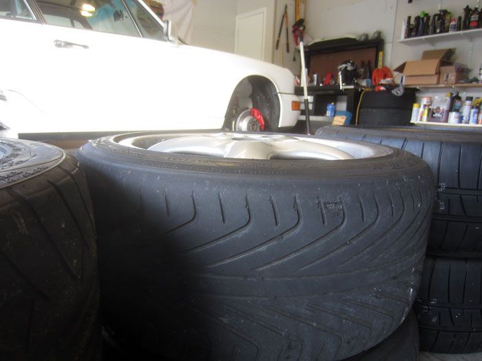
245/40 PS2s in the center vs the 255/40 BFGs on the right, not that big of a difference for these sizes.
Last edited by Vandit; 06-01-2014 at 09:58 AM.
The following users liked this post:
Rephlex (05-03-2022)
06-01-2014, 12:25 AM
#4
Nordschleife Master
Thread Starter
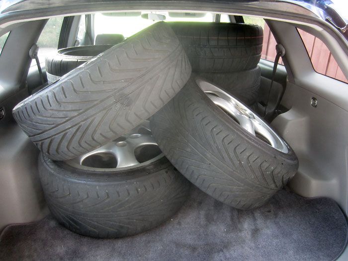
8 tires in the back of my hatch, not bad.
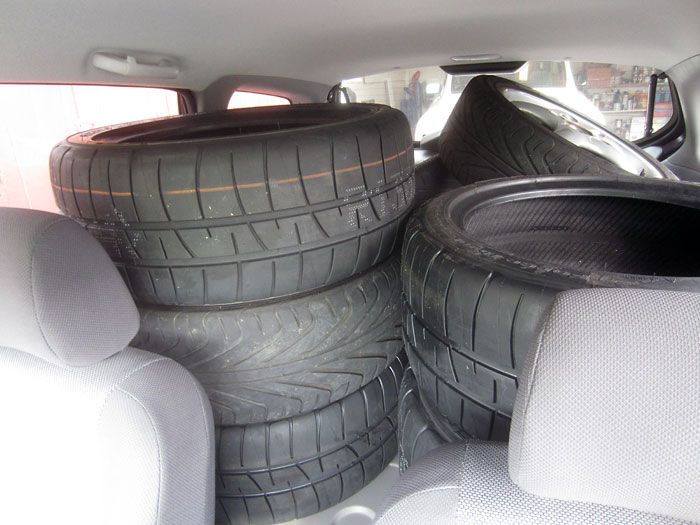
Off to get mounted and balanced.
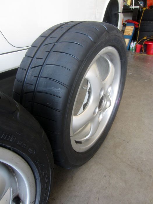
Big ole 225/45 BFGs on 7” Cup 2 wheel.
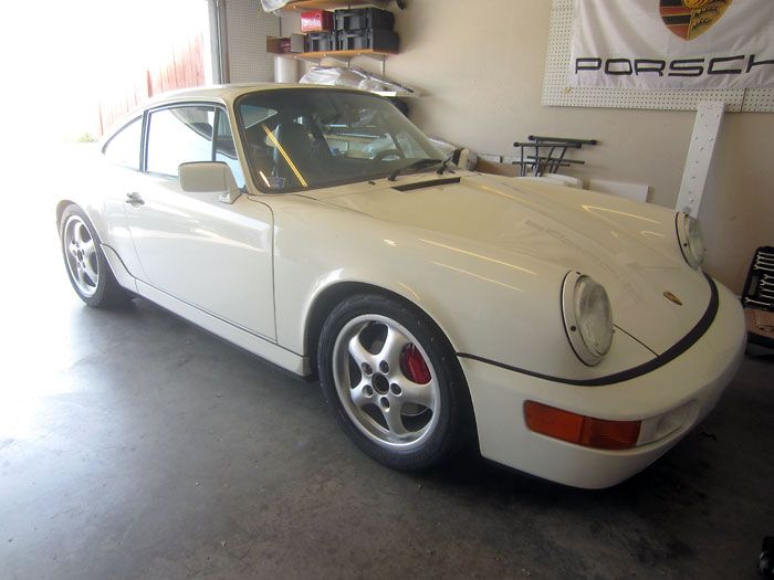
Back on the ground, now w/ lots more grip.
Out at an autocross.
Looking purposeful on the grid.
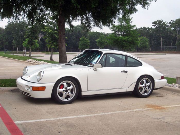
Overall, I’m very happy with the outcome of all these new parts and all the sweat equity that I contributed on nights and weekends in my garage.
The actual installation of all this stuff actually took place between December 2012 and March 2013, it’s just taken me forever to sit down and go through all the content and arrange it in the form of a thread, lol.
I would have liked to go with a higher-end coilover setup, but the displeasure of pushing the car on the old suspension was just too great to wait around for my budget to afford some KW V3 or Clubsports. Eventually, I’ll get there, but for now, I think it turned out very well and my course times and ability to confidentially push the car to the limit at autocross had been improved tremendously.
 06-01-2014, 03:08 AM
#6
Instructor
This was a really good post with alot of pictures and links to others to complete the these upgrades.
I need to get better to start collecting things I need for mine ;-)
I need to get better to start collecting things I need for mine ;-)
Trending Topics

 06-01-2014, 04:51 AM
#10
Intermediate

Join Date: Mar 2014
Location: hertfordshire
Posts: 31
Likes: 0
Received 0 Likes
on
0 Posts
Thanks for a brilliant write up,not only for those with the capabilities to undertake the job, but also for those who might *think* they can undertake it to realise that maybe it is one to leave for someone better equipped!
It is this sort of detail that makes this forum such a great resource...thanks again for taking the time and enjoy the fruits of your labour in a car in the best colour!
It is this sort of detail that makes this forum such a great resource...thanks again for taking the time and enjoy the fruits of your labour in a car in the best colour!
 06-01-2014, 09:26 AM
#12
Great documentation. I did the same project in my garage this past winter. Your photos and tips really helped me. My car is on the road again and the new suspension is amazing.
06-01-2014, 12:11 PM
#14
Instructor
I literally watched my indie do this on another 964 yesterday and thought to myself afterwards, bugger, I should have made a photo record for future use.
So thanks for posting Vandit, a great DIY record!
TJ
So thanks for posting Vandit, a great DIY record!
TJ
06-01-2014, 03:08 PM
#15
Rennlist Member
Great post. Helps quite a bit in thinking of my own suspension work in the future. Thx for posting with the detail photos.