When you click on links to various merchants on this site and make a purchase, this can result in this site earning a commission. Affiliate programs and affiliations include, but are not limited to, the eBay Partner Network.
Interesting. I thought the new turbo was larger than the one used in the old system. It may just be the camera angle, but the new turbo housing looks slightly smaller.
Compressor is effectively the same as in the previous version. The previous version was an upgrade over the earlier version, in which we hit the mass flow limit. With these compressors, the bottleneck was the flow paths into the compressor and out of the compressor thru the intercooler etc. With lower compression, we could've squeezed more out of that system, but the efficiency would've suffered. So this new system was designed to relieve all known bottlenecks and constraints on efficiency.
I though but the goal of this project was not to cut the car body.
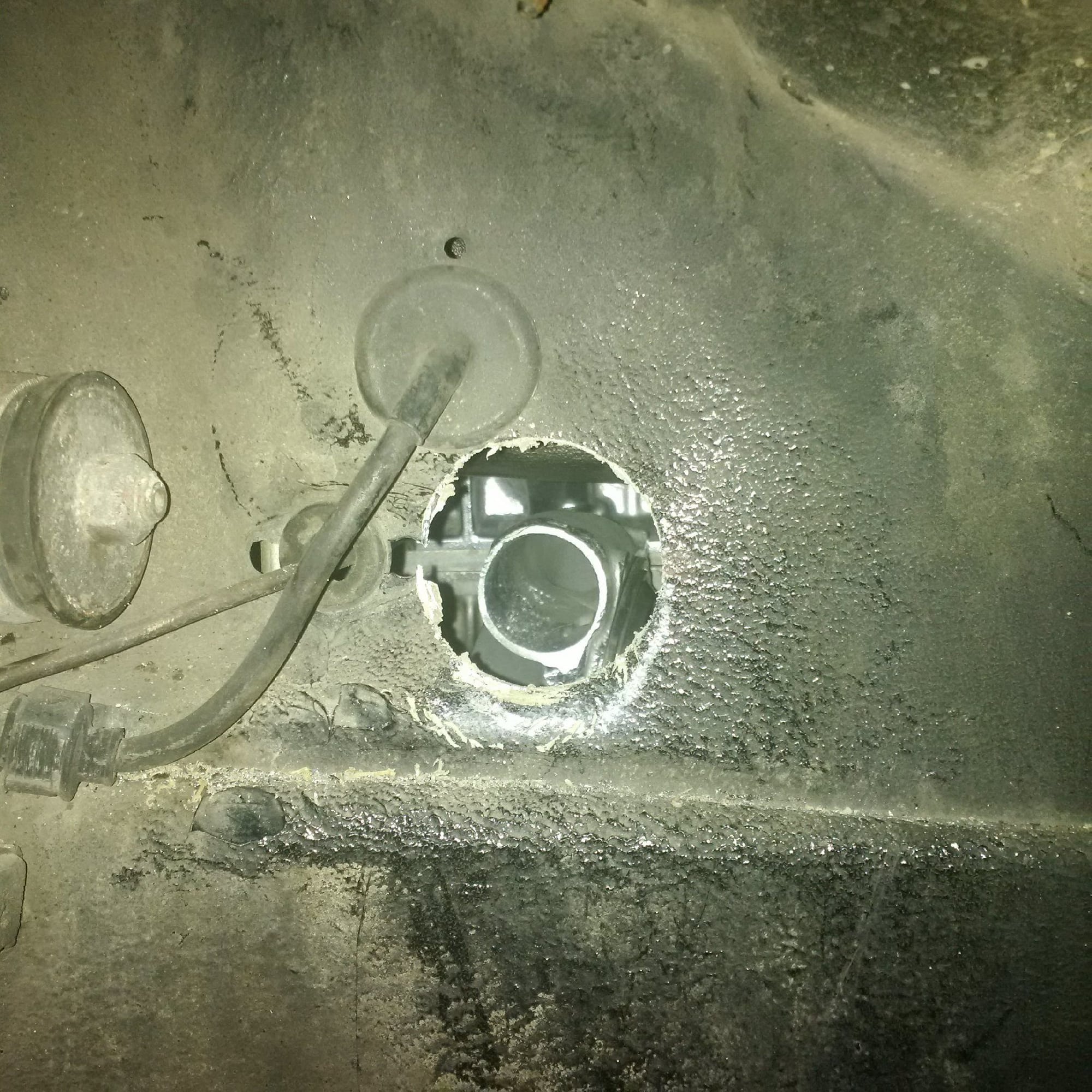
There's already holes in the front bumper cover and other minor modifications such as making holes to panels for pipes. What we don't want to do is modify the chassis in places that are important to the structural integrity of the chassis. That's both a safety and cost consideration, to do that kind of modifications of the chassis right is expensive. Cutting a hole thru a single sheet panel is not.
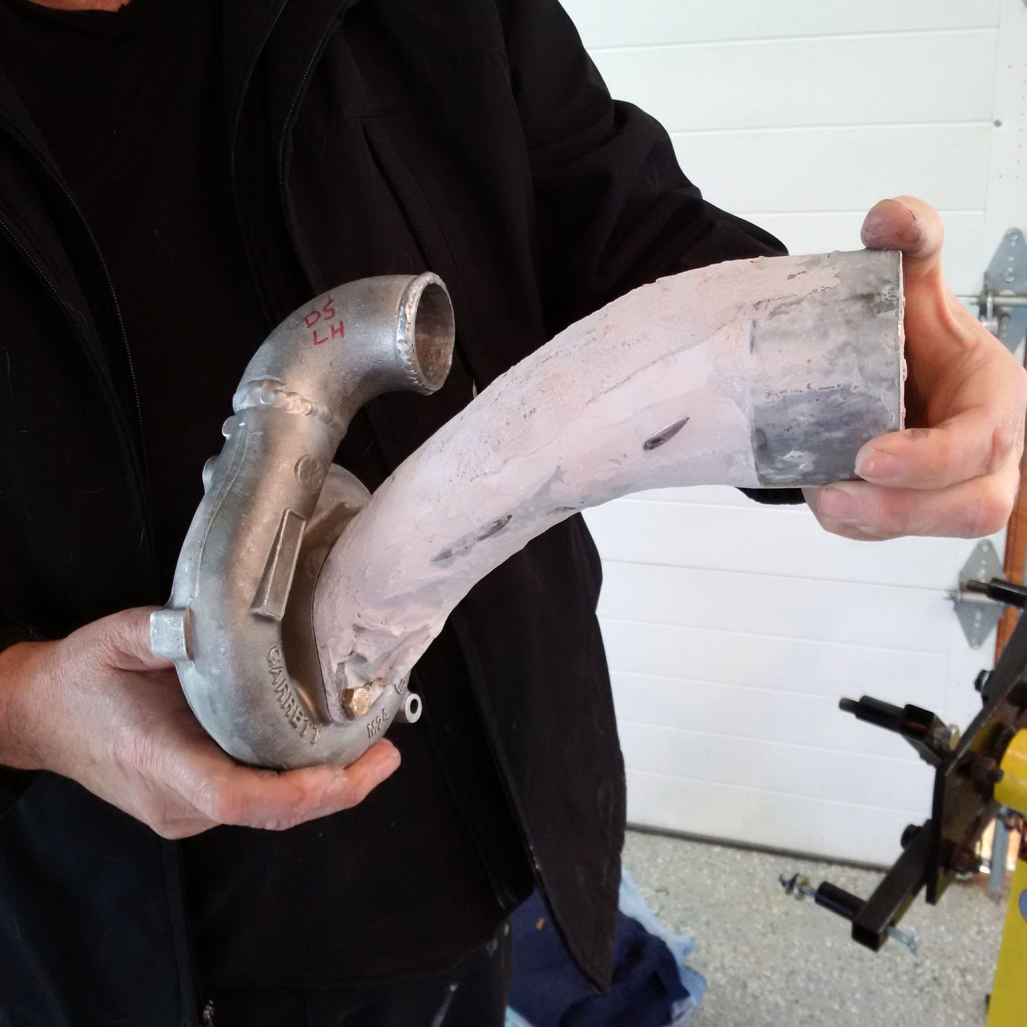
This new version of the system will shift a lot of the labor cost to hard parts cost. Almost all steps will be well enough defined that they could be subcontracted out. The prime example is the exhaust manifolds, which aren't hand fitted and welded from tens of hand-fabricated pieces anymore, instead they are simply cast. But it's the same philosophy throughout this redesign.
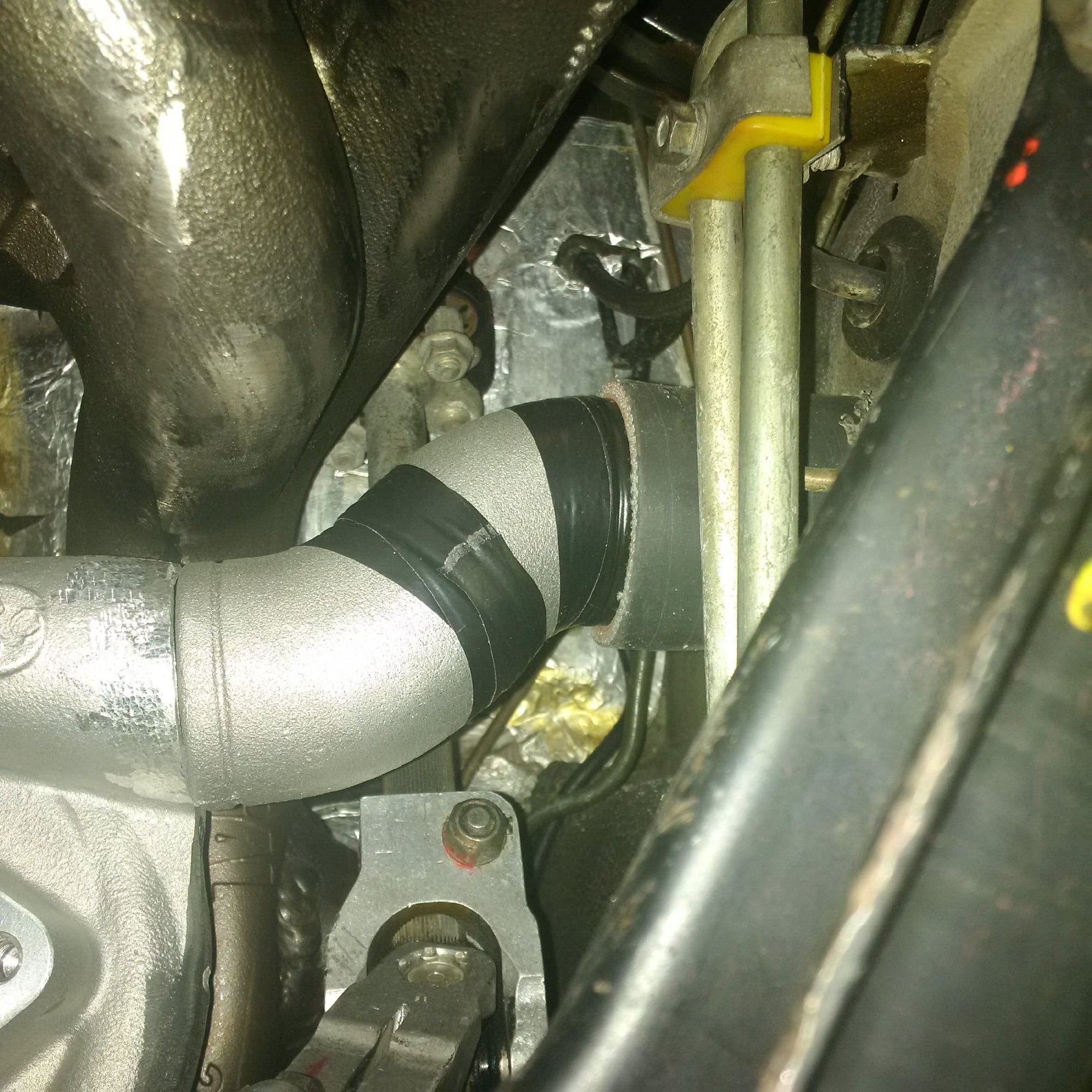
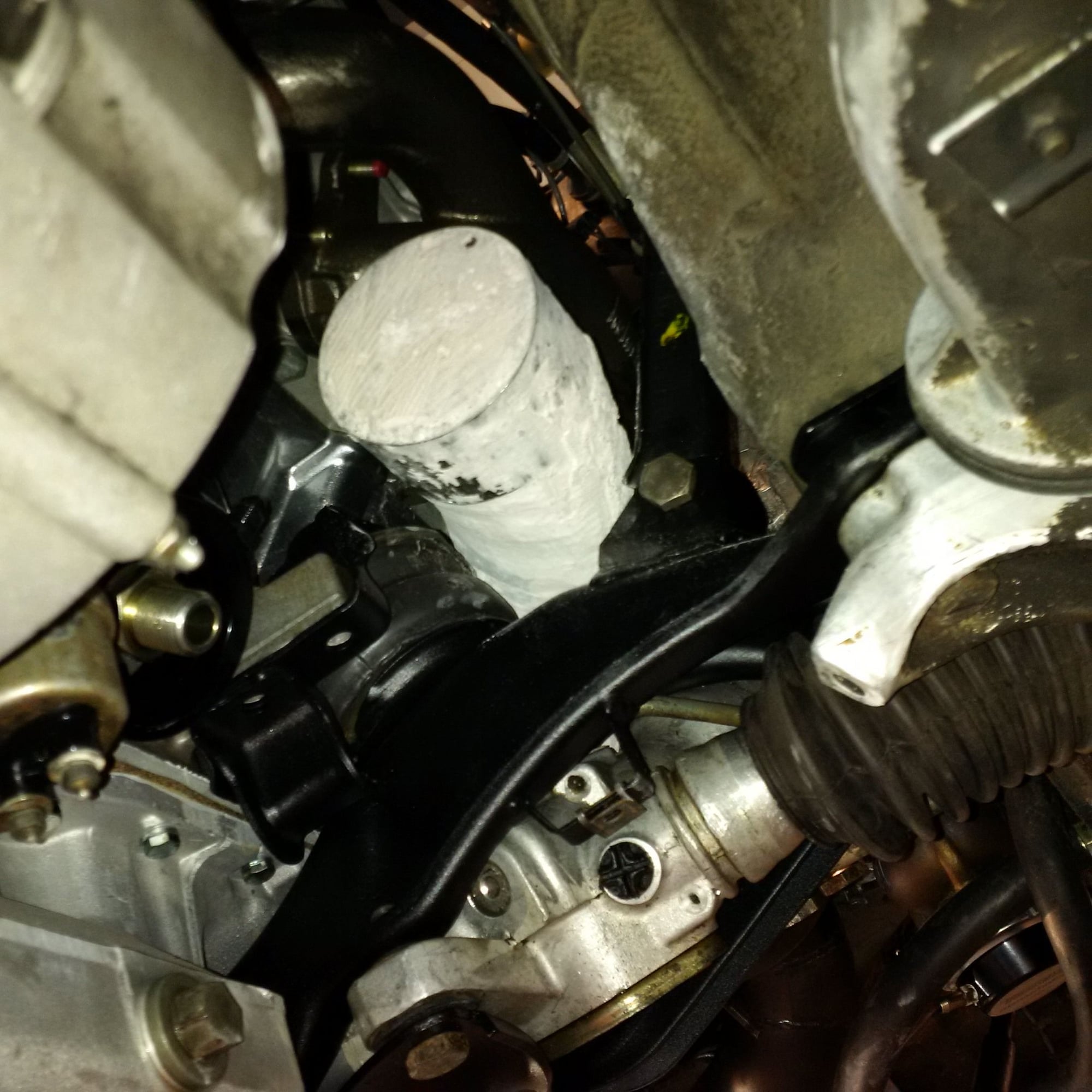
Hopefully, these photos illustrate one of the motivations for going thru the fenderwell wall. This leaves more room for a big-a$$ compressor inlet pipe. Where there used to be two pipes, now there's only one really big pipe.
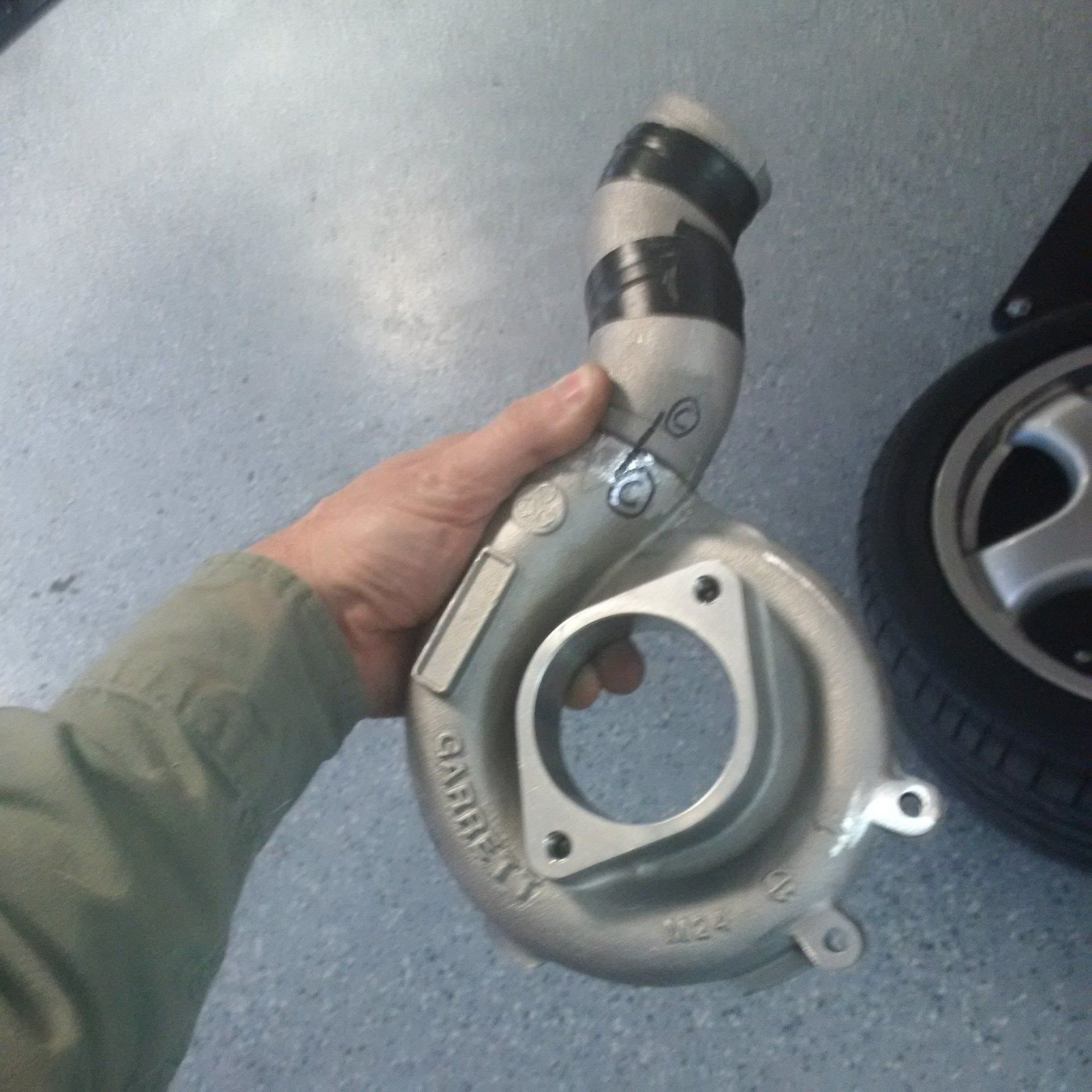
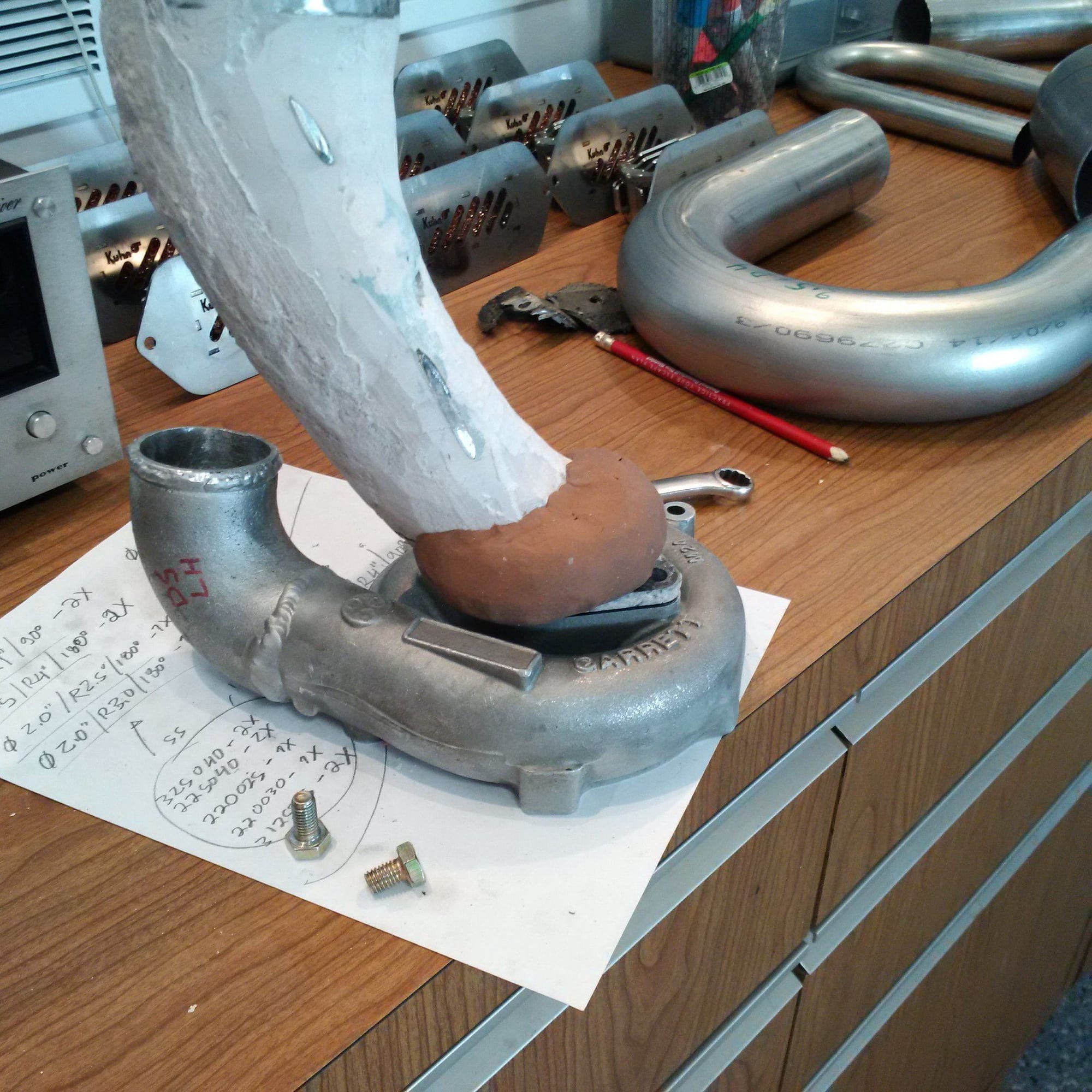
It's not all cad work, there's some good old fashioned hand forming there as well. These are models, the actual piece will be steel reinforced silicone.
Note the banjo feature that's added to the compressor inlet. We'll have to enter the compressor inlet at an angle because of the bottom subframe / cross member / whatnot. This means that we need to create an efficient way for the air to turn into the inlet from all sides, just a cheater-cut joint there would be... Uncivilized.
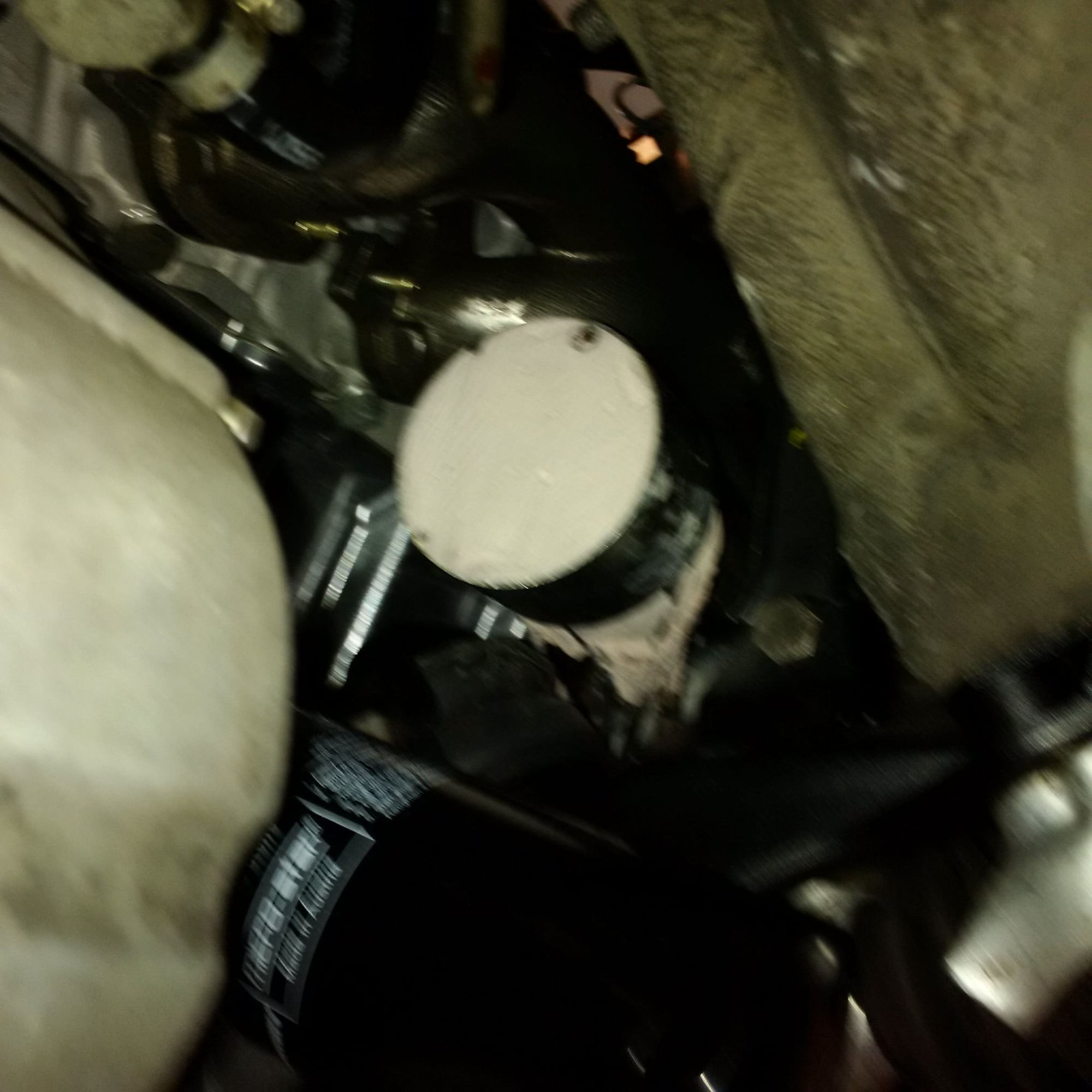
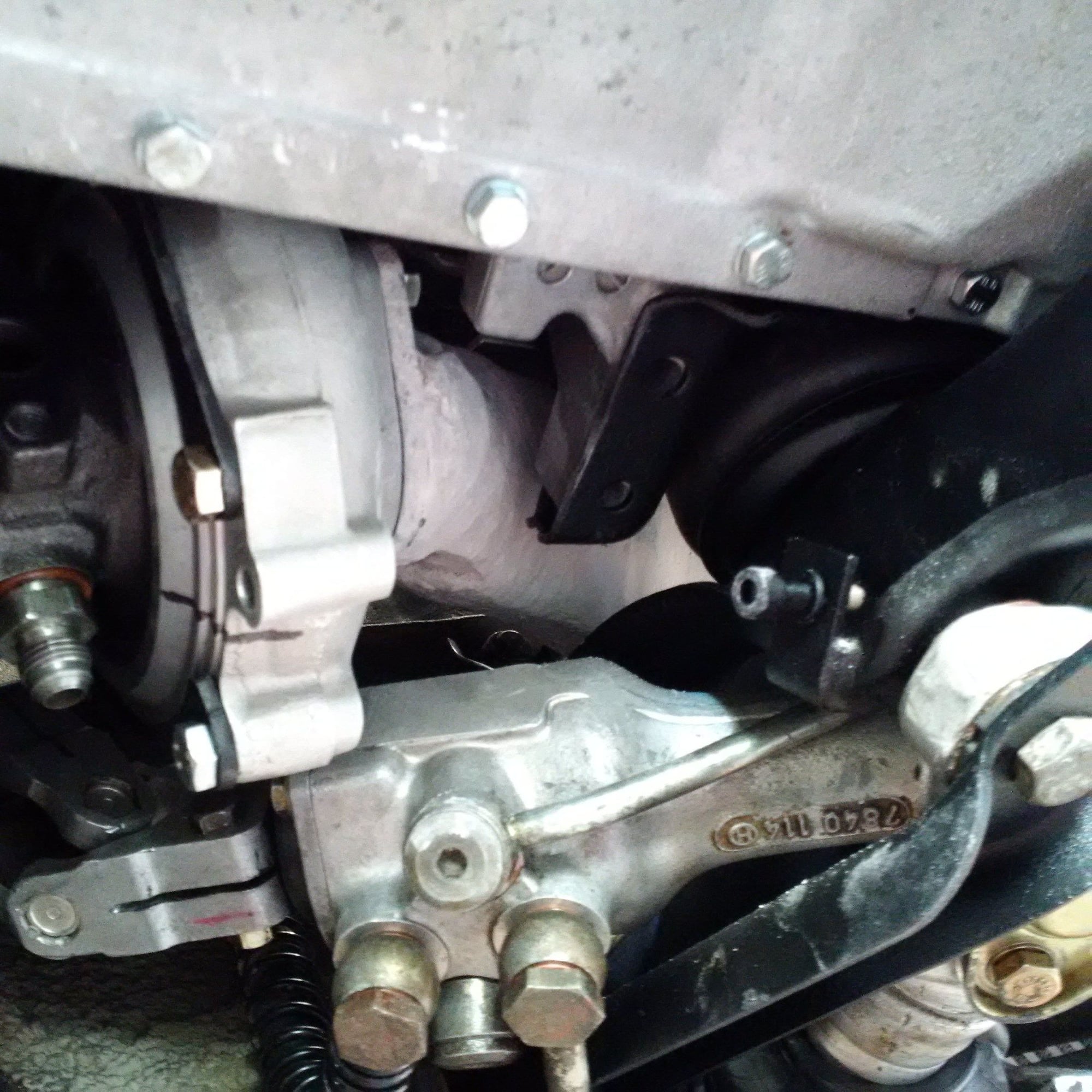
Wow, that's a tight fit! Is there any room for the various components to move as the car is in motion?
Yes, it's all properly provisioned for. The good news is that a lot of this stuff is reasonably close to the pivot point. Still, both clearance and compliance needs to be there, the requirements are just somewhat smaller than far away from the pivot point.
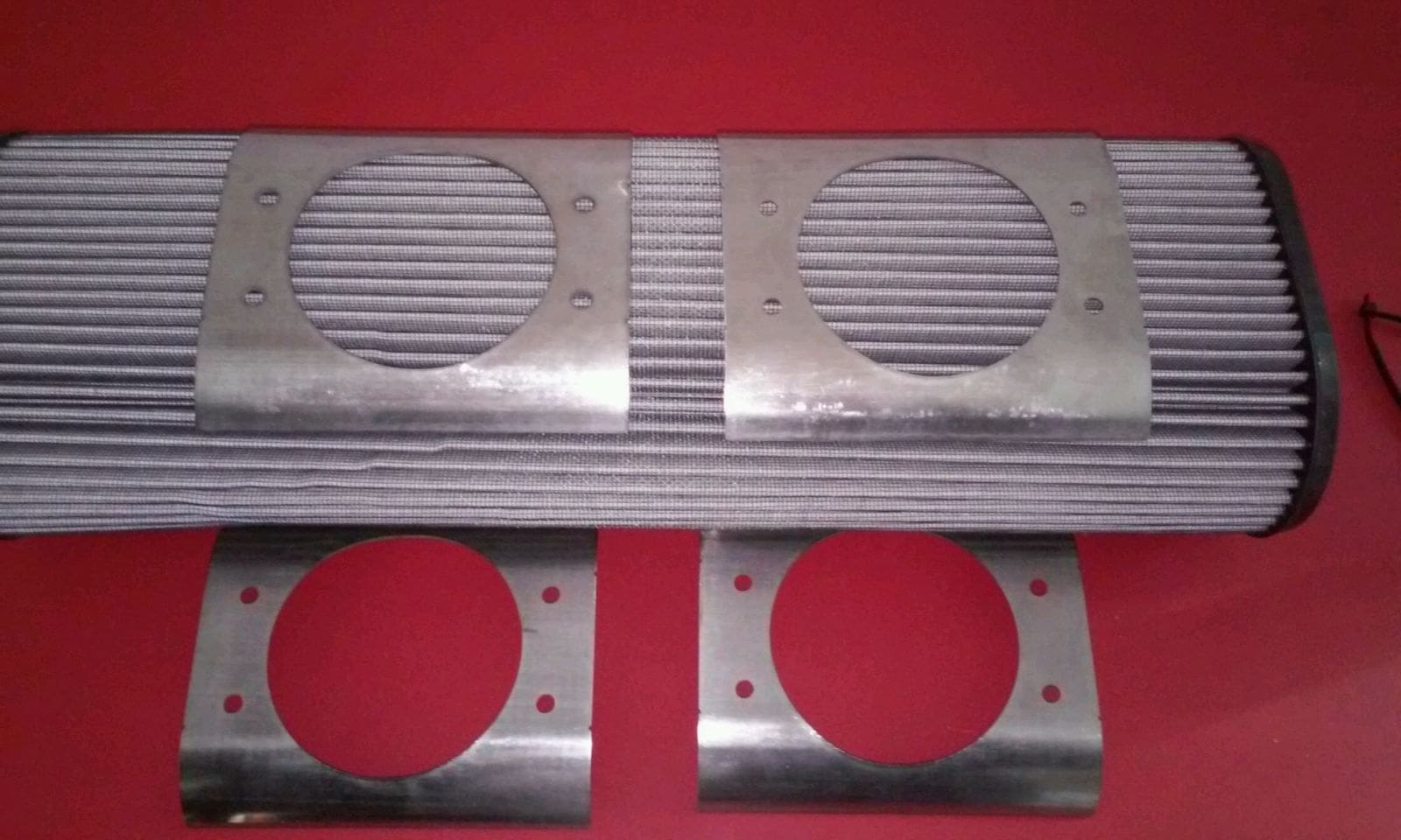
This filter and piping will not cause a restriction
These are the components used to put the filter element together. Those are 3.5" holes, they will flow required air at a minimal pressure loss.
I'm feeling great about these ducts breathing up to the compressor inlet piece. That's the challenge, upstream of it any breathing issues are now solved.
If you're referring to the air oil separator in the chimney, those come either with our without the scrubber media. Which one is appropriate depends entirely on how the rest of the breather system is configured.


 01-03-2016, 11:53 AM