When you click on links to various merchants on this site and make a purchase, this can result in this site earning a commission. Affiliate programs and affiliations include, but are not limited to, the eBay Partner Network.
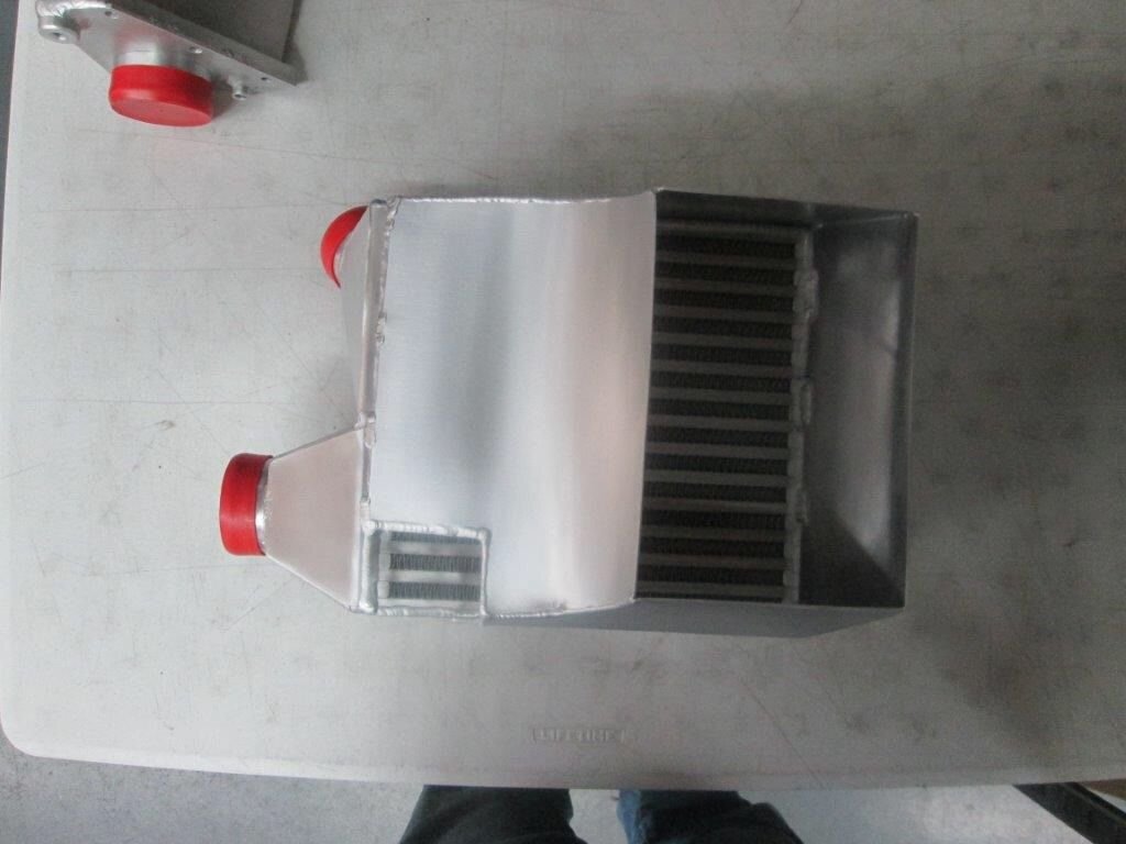
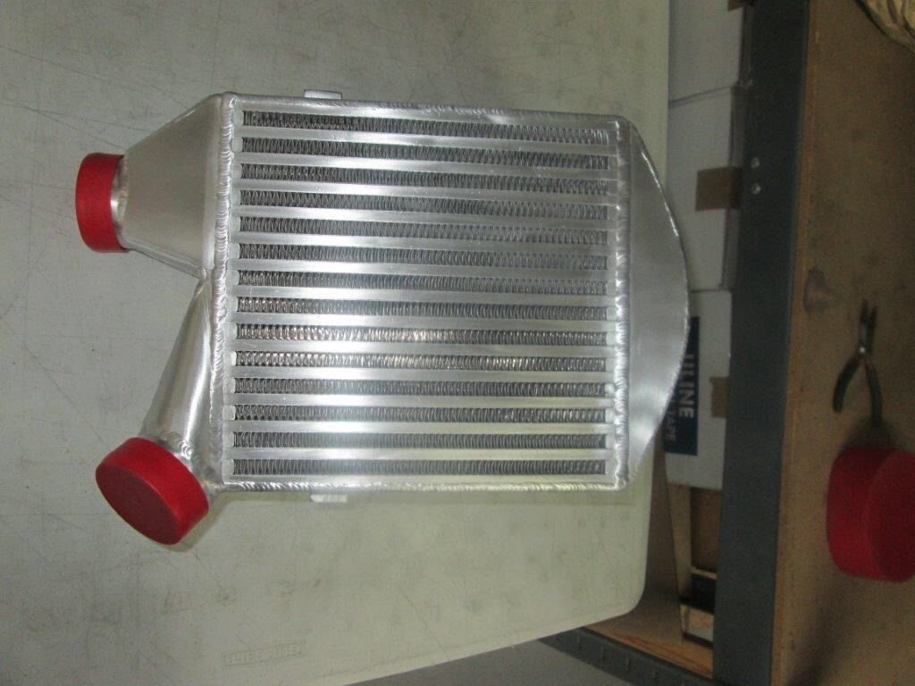
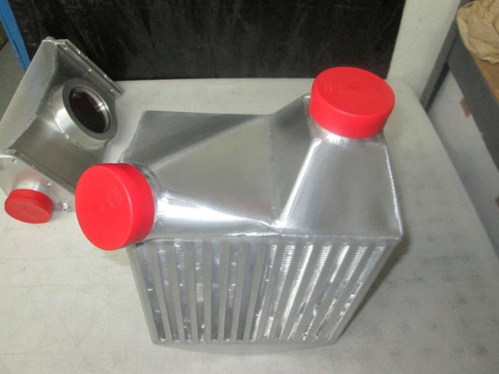
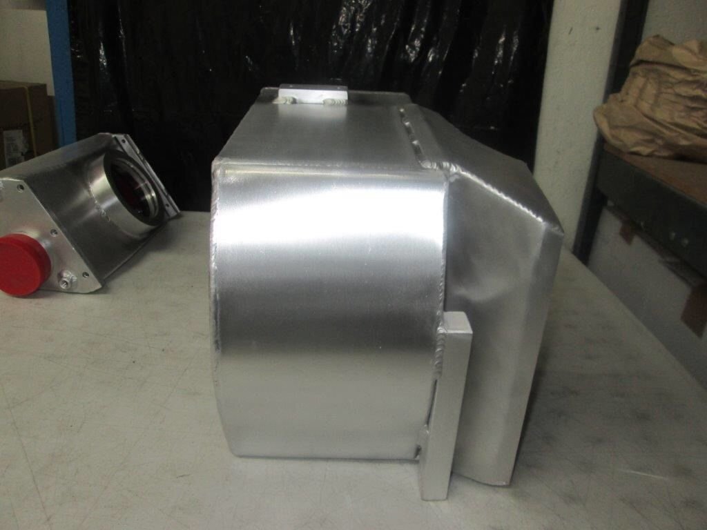
Biggest intercoolers that anyone will ever fit inside the stock S4 frnders
These have cooling capacity slightly greater than the 944 turbo and 968 turbo s intercoolers, and there's two of them.
The cross sectional area and flow path length are close to optimal match for the internal turbulators in the core. Coincidentally or not, the csa and length ended up pretty close to the 951 intercoolers dimensions.
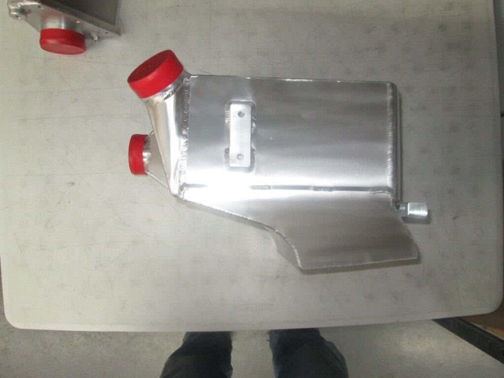
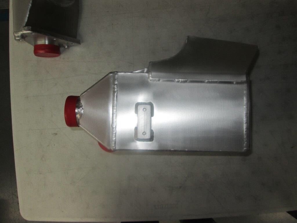
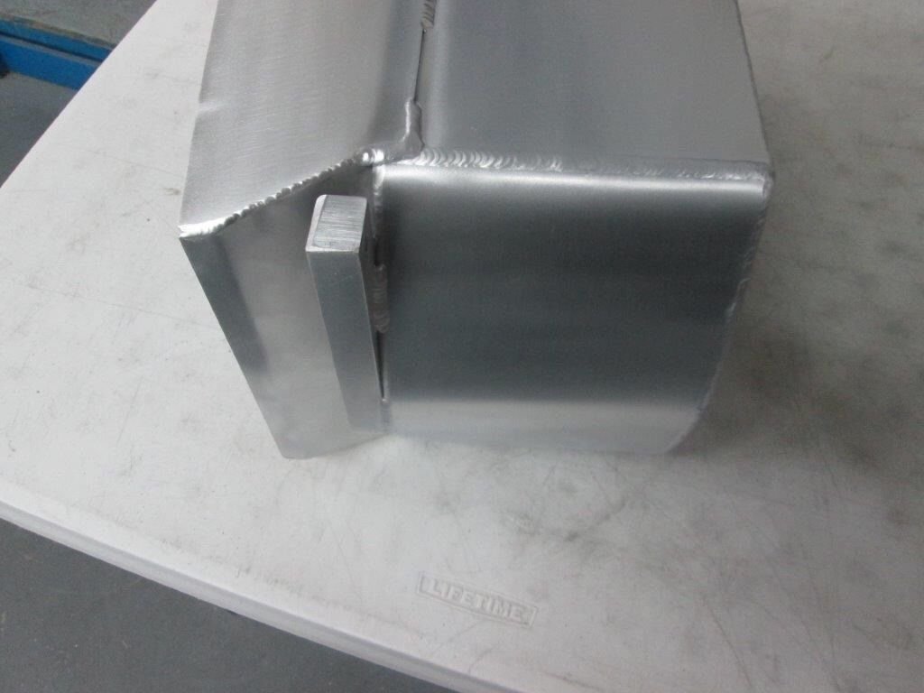
The entry end tank is pretty carefully designed and fabricated to minimize the pressure head loss due to turbulence.
Shroud is integrated which will allow attaching the ducting to it relatively easily.
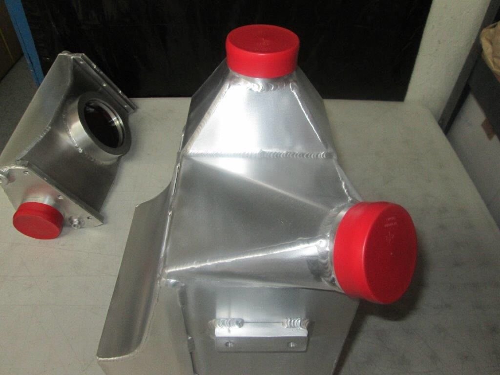
These have cooling capacity slightly greater than the 944 turbo and 968 turbo s intercoolers, and there's two of them.
The cross sectional area and flow path length are close to optimal match for the internal turbulators in the core. Coincidentally or not, the csa and length ended up pretty close to the 951 intercoolers dimensions.
The entry end tank is pretty carefully designed and fabricated to minimize the pressure head loss due to turbulence.
Shroud is integrated which will allow attaching the ducting to it relatively easily.
Looking good sir...
On another note, I might have to buy another 928 and John's hot side parts and use my AWIC setup to see if I can dispense with the bundle of snakes under the hood of a TT setup...
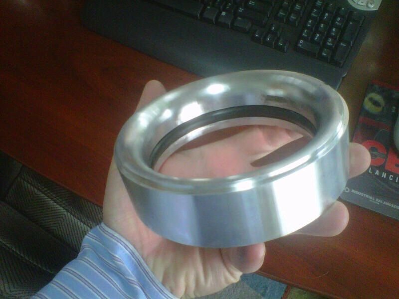
The forces on that air box are simply incredibly high. Suppose that one runs 30 psi boost. The force pulling the air box out away from the engine is 30 psi times the cross sectional area of the maf housing. That is in the hundreds of pounds. This requires two sturdy brackets and a different kind of o-ringed and collared coupling between the air box and maf housing. In addition, the flow path has to be efficient and relatively smooth to produce a well enough developed flow to the maf sensor itself. Here's the magic piece that is now part of the air box:
On another note, I might have to buy another 928 and John's hot side parts and use my AWIC setup to see if I can dispense with the bundle of snakes under the hood of a TT setup...
That's going to be really difficult. First you need to size the turbos in a way that makes sense for the power levels we're looking for, and they are big. Then, there's almost no room to run anything including the boost pipe up by the valve covers. Turbines and exhaust piping will block the route behind the engine. So the only routes are either forward or into the wheelwell. Forward route is blocked by auxiliaries if those are retained and by the fresh air inlet to the compressor if that is sized appropriately for the power level. If you go into the wheelwell, there's no practical way to punch the pipe back into the engine compartment in the rear to the natural location of the AWIC. You have to run it forward instead. In the end, the AAIC is functionally superior and has no plumbing penalty relative to AWIC in a twin turbo 928.
Twin Turbo 928 fixed and back out there terrorizing the streets!
Originally Posted by ptuomov
That's going to be really difficult. First you need to size the turbos in a way that makes sense for the power levels we're looking for, and they are big. Then, there's almost no room to run anything including the boost pipe up by the valve covers. Turbines and exhaust piping will block the route behind the engine. So the only routes are either forward or into the wheelwell. Forward route is blocked by auxiliaries if those are retained and by the fresh air inlet to the compressor if that is sized appropriately for the power level. If you go into the wheelwell, there's no practical way to punch the pipe back into the engine compartment in the rear to the natural location of the AWIC. You have to run it forward instead. In the end, the AAIC is functionally superior and has no plumbing penalty relative to AWIC in a twin turbo 928.
Hmmmm, interesting packaging info....
I'm curious about the outlet pipe diameters of the GT35's you are going to run.. Are they more than 2.5" or 63mm? I had spoken to John before he built your car, and if my memory is good (probably not) I thought the compressor outlet piping was about 52 mm on the GT28's...
On another note, the 6 core coolers I have now can support 900+ hp of airflow at >90% efficiency. Getting to 1200 or 1500 hp at the same efficiency only requires additional cores.. Maybe you guys are going for 2000+hp.....
Have you measured the pressure drop from the compressor exit to the intake port? (Not just across the IC, but across the entire system past the TB to see what the system drop is?)
By a total coincidence, I might actually fly over my new daily driver that is crossing the Atlantic in the opposite direction. My 2016 AMG S65 Coupe is on board of Aniara on the way to Baltimore:
In terms of the compressor cover outlet, the actual outlet diameter is not very important. What is important is how far one can extend a diffuser without bends from that outlet. For packaging reasons, the usual answer is "not much", but in this new build the goal is to create an outlet a bit closer to the ideal. Don't take me wrong, even very cramped compressor outlet plumbing can make a lot of power. It's just that when one is trying to create a favorable intake to exhaust pressure ratios, avoiding any turbulence is the key. Consequently, all pipes will be as large as possible given the space available and all changes in cross sectional area will be very gradual.
Yes, we've mapped the static pressure at every relevant point in the previous version of the system and then computed the velocity pressures and from there the total pressure losses for each section. The new intercooler will cool a lot better but with some additional pressure loss compared to the old intercoolers. We expect to pick up as much or more from in savings from the closer to ideal piping to offset that pressure loss.
Originally Posted by blau928
I'm curious about the outlet pipe diameters of the GT35's you are going to run.. Are they more than 2.5" or 63mm? I had spoken to John before he built your car, and if my memory is good (probably not) I thought the compressor outlet piping was about 52 mm on the GT28's...
On another note, the 6 core coolers I have now can support 900+ hp of airflow at >90% efficiency. Getting to 1200 or 1500 hp at the same efficiency only requires additional cores.. Maybe you guys are going for 2000+hp.....
Have you measured the pressure drop from the compressor exit to the intake port? (Not just across the IC, but across the entire system past the TB to see what the system drop is?)
In terms of the compressor cover outlet, the actual outlet diameter is not very important. What is important is how far one can extend a diffuser without bends from that outlet. For packaging reasons, the usual answer is "not much", but in this new build the goal is to create an outlet a bit closer to the ideal. Don't take me wrong, even very cramped compressor outlet plumbing can make a lot of power. It's just that when one is trying to create a favorable intake to exhaust pressure ratios, avoiding any turbulence is the key. Consequently, all pipes will be as large as possible given the space available and all changes in cross sectional area will be very gradual.
Yes, we've mapped the static pressure at every relevant point in the previous version of the system and then computed the velocity pressures and from there the total pressure losses for each section. The new intercooler will cool a lot better but with some additional pressure loss compared to the old intercoolers. We expect to pick up as much or more from in savings from the closer to ideal piping to offset that pressure loss.
I fully agree with you on the number of bends/turns and turbulence. This is exactly why I am curious about the pressure drop the engine sees at the valve, as there are so many bends in the stock intake, that I think the compressor has a bit to do to overcome all the bends etc. in the TT AAIC system.
Do you mind sharing what the system drop was from compressor to valve? (If you don't, I can understand that you want to keep it proprietary for your own reasons.)
Not trying to hog your thread...
On this specific subject, when I designed my setup, I tried to take into account the least amount of bends, and the shortest path possible to the valve from the compressor.
The system has 5 turns after the compressor in total.
1. Exit compressor and turn Right/Left in upper plenum
2. Turn in upper plenum to enter AWIC
3. Turn through AWIC to enter Lower IC outlet plenum
4. Turn in plenum to get into runner port
5. Turn in runner to enter valve/chamber
The key part is that the AWIC cores introduce a high degree of laminar flow based on the design, as well as less than 1psi pressure drop at max flow across the core as documented by Laminova in turn #3.
In the outlet plenum, I incorporated trumpets to encourage good runner filling with a reduction in laminar loss and flow disturbance into the ports and to compensate for turn #4.
The runners themselves have a decreasing radius to increase velocity as confirmed by my CFD analysis, and should help with cylinder filling based on my research.
Here is a cutaway/section showing the short path and number of turns in my AWIC . There are pressure ports for measuring pre and post IC as well, so I hope to document the system pressure drop once it's running. There are also lots of other aerodynamic principles applied in the CAD model that are probably not able to be seen by many.
We did measure all the pressure static losses and estimated total pressure losses and loss coefficients between the air cleaner and the plenum feeding the intake manifold. I don't have those data in front of me, but it was perfectly acceptable for 700 rwhp. Holding the loss coefficients constant, the system would have been clearly inadequate for 1000 rwhp.
The losses grow at the square of the velocity (assuming constant loss coefficients). As long as the cross-sectional area is large and thus velocity low, you can have as many turns as you want without any meaningful pressure loss. It's only when the kinetic energy in the flow grows that turns start causing meaningful pressure losses.
The new system will have the pressure pipes from 2.5-2.75" OD thin wall SS. All the mandrel bends have quite long radii. There are some pictures of the pipes earlier in the thread. When possible, the cross-sectional area is gently increased to reduce the velocity before turns. The plenum box, for example, is narrower to allow for a larger entry pipe with large turn radius. There's a conical diffuser stepping up the pipe size before that 90-degree turn.
The intercooler entry tank is critical to the overall loss coefficient, by the way. the 180-degree turn at the bottom doesn't cause much loss because the flow is slow enough there. And the exit is contracting cross-sectional area which is always easier to do without total pressure losses. But the expansion into the entry end tank is where a good design makes a big difference compared to a bad design.
We so far haven't tried to measure any pressures near the intake valve. The old equipment was inadequate for measuring the pulsing flow. The new equipment, which is turning out to be a b!itch to install, should allow measuring the pulsing flow.
Your system looks very good in terms of efficiency. There are two places where I'd make sure everything works out as efficiently as possible. First, the intake runner will have an S-shaped turn, which can cause curve ***** to flow in some cases. There's the turn around the injectors and then there's another, opposing turn into the valves. Second, the air intake into the supercharger is only "boosted" by atmospheric pressure, so the filters and the ducts feeding the supercharger will have to be generously sized.
Originally Posted by blau928
I fully agree with you on the number of bends/turns and turbulence. This is exactly why I am curious about the pressure drop the engine sees at the valve, as there are so many bends in the stock intake, that I think the compressor has a bit to do to overcome all the bends etc. in the TT AAIC system.
Do you mind sharing what the system drop was from compressor to valve? (If you don't, I can understand that you want to keep it proprietary for your own reasons.)
Not trying to hog your thread...
On this specific subject, when I designed my setup, I tried to take into account the least amount of bends, and the shortest path possible to the valve from the compressor.
The system has 5 turns after the compressor in total.
1. Exit compressor and turn Right/Left in upper plenum
2. Turn in upper plenum to enter AWIC
3. Turn through AWIC to enter Lower IC outlet plenum
4. Turn in plenum to get into runner port
5. Turn in runner to enter valve/chamber
The key part is that the AWIC cores introduce a high degree of laminar flow based on the design, as well as less than 1psi pressure drop at max flow across the core as documented by Laminova in turn #3.
In the outlet plenum, I incorporated trumpets to encourage good runner filling with a reduction in laminar loss and flow disturbance into the ports and to compensate for turn #4.
The runners themselves have a decreasing radius to increase velocity as confirmed by my CFD analysis, and should help with cylinder filling based on my research.
Here is a cutaway/section showing the short path and number of turns in my AWIC . There are pressure ports for measuring pre and post IC as well, so I hope to document the system pressure drop once it's running. There are also lots of other aerodynamic principles applied in the CAD model that are probably not able to be seen by many.
We did measure all the pressure static losses and estimated total pressure losses and loss coefficients between the air cleaner and the plenum feeding the intake manifold. I don't have those data in front of me, but it was perfectly acceptable for 700 rwhp. Holding the loss coefficients constant, the system would have been clearly inadequate for 1000 rwhp.
The losses grow at the square of the velocity (assuming constant loss coefficients). As long as the cross-sectional area is large and thus velocity low, you can have as many turns as you want without any meaningful pressure loss. It's only when the kinetic energy in the flow grows that turns start causing meaningful pressure losses.
The new system will have the pressure pipes from 2.5-2.75" OD thin wall SS. All the mandrel bends have quite long radii. There are some pictures of the pipes earlier in the thread. When possible, the cross-sectional area is gently increased to reduce the velocity before turns. The plenum box, for example, is narrower to allow for a larger entry pipe with large turn radius. There's a conical diffuser stepping up the pipe size before that 90-degree turn.
The intercooler entry tank is critical to the overall loss coefficient, by the way. the 180-degree turn at the bottom doesn't cause much loss because the flow is slow enough there. And the exit is contracting cross-sectional area which is always easier to do without total pressure losses. But the expansion into the entry end tank is where a good design makes a big difference compared to a bad design.
We so far haven't tried to measure any pressures near the intake valve. The old equipment was inadequate for measuring the pulsing flow. The new equipment, which is turning out to be a b!itch to install, should allow measuring the pulsing flow.
Your system looks very good in terms of efficiency. There are two places where I'd make sure everything works out as efficiently as possible. First, the intake runner will have an S-shaped turn, which can cause curve ***** to flow in some cases. There's the turn around the injectors and then there's another, opposing turn into the valves. Second, the air intake into the supercharger is only "boosted" by atmospheric pressure, so the filters and the ducts feeding the supercharger will have to be generously sized.
Thanks for the kind words.
Gotcha on the measuring.. I'm really curious to see what your findings are on the new measuring equipment. I toyed with the idea of putting sensor ports in the runners just before the injectors, but am still digging into sensor corruption and faults caused by the fuel in the mixture, so still open on the checklist.. However, I plan to use EGT's and plumb the datalogger so maybe it won't matter if I just get the IC outlet manifold readings.
I fully agree on the intake restriction, and the plan is for dual 75mm tubes to the TB, similar to Dave roberts' "Blackbird" filters.
The hard part is the air filters, as many companies do not publish the flow data, so I may have to do a work around and fab a special airbox, but that should be relatively easy, or I can use 2 928 filters laid longitudinally between the valve covers and the fender as one was enough for a 959, so 2 should be fine.
There is only one turn in the runner, and it will be port matched to the head so the turn will become a more open "C". It probably looks like more, but it is a decreasing radius inverted loft to increase velocity based on the aero principles of flow. The CFD showed the stream lines, and pressure zones, and so far so good. The low pressure zone is in the short turn area opposite where the injectors are located so they don't have to fight too much against the manifold pressure. (Aerodynamic trickery of CFD etc. etc.)
The turn at the valve where it swirls and tumbles into the chamber is what it is, so I didn't count that. (Yet) I wasn't planning on reshaping the intake throat, floor, and valve area as yet. First the stock as cast head, then later I can play headsmith on the ports in the head....
From the research I have seen from Kenne Bell, a single inlet tube 4" diameter with one of their large K&N mammoth air filters (forgot the #, but it's on their website) on this MX422 supercharger has a 0psi drop between the filter and the compressor inlet. I have one of these filters, and will cut it open to measure the area of the filter media to see how much area is needed on the two sides of the intake.
With dual 3" inlets, I'm thinking it will be fine once I can size the filters properly. (Mandatory radiused bends etc.. In any case, I can put in sensors and measure with the datalogger and see how best it can be. Using the rule of thumb that the engine needs 1.5 CFM per HP, and the compressor is capable of 825 HP before maxing out, in round numbers 1300 CFM with 675 CFM per side. Of course, I want as much as possible, as I can upgrade the compressor to a 2.8L liquid cooled bearing case unit, and that's good for 1000+ HP so min 1500 CFM.. So, if I get to 750 CFM per bank, I'll be happy.. For now.....


 07-17-2015 | 04:49 PM