When you click on links to various merchants on this site and make a purchase, this can result in this site earning a commission. Affiliate programs and affiliations include, but are not limited to, the eBay Partner Network.
One point I forgot to mention, is that in a crankcase with a vacuum, the shaped counterweights won't matter as there is little/no resistance in a vacuum/dry sump race motor. In a non vacuum motor, different story...
It may be that there's a benefit in a wet sump engine without a vacuum pump. It's just that I've never seen it demonstrated in any published tests. The published tests all have the problem that the don't hold the main bearing loads constant between the two cranks. If you know of a correctly implemented test on the topic I'd love to see it.
One point I forgot to mention, is that in a crankcase with a vacuum, the shaped counterweights won't matter as there is little/no resistance in a vacuum/dry sump race motor.
...
I'd always assumed the knife edge and shaped counterweights were an attempt to reduce/control splashing of the motor oil.
Got a new and more accurate combustion model. Got a better turbine model as well.
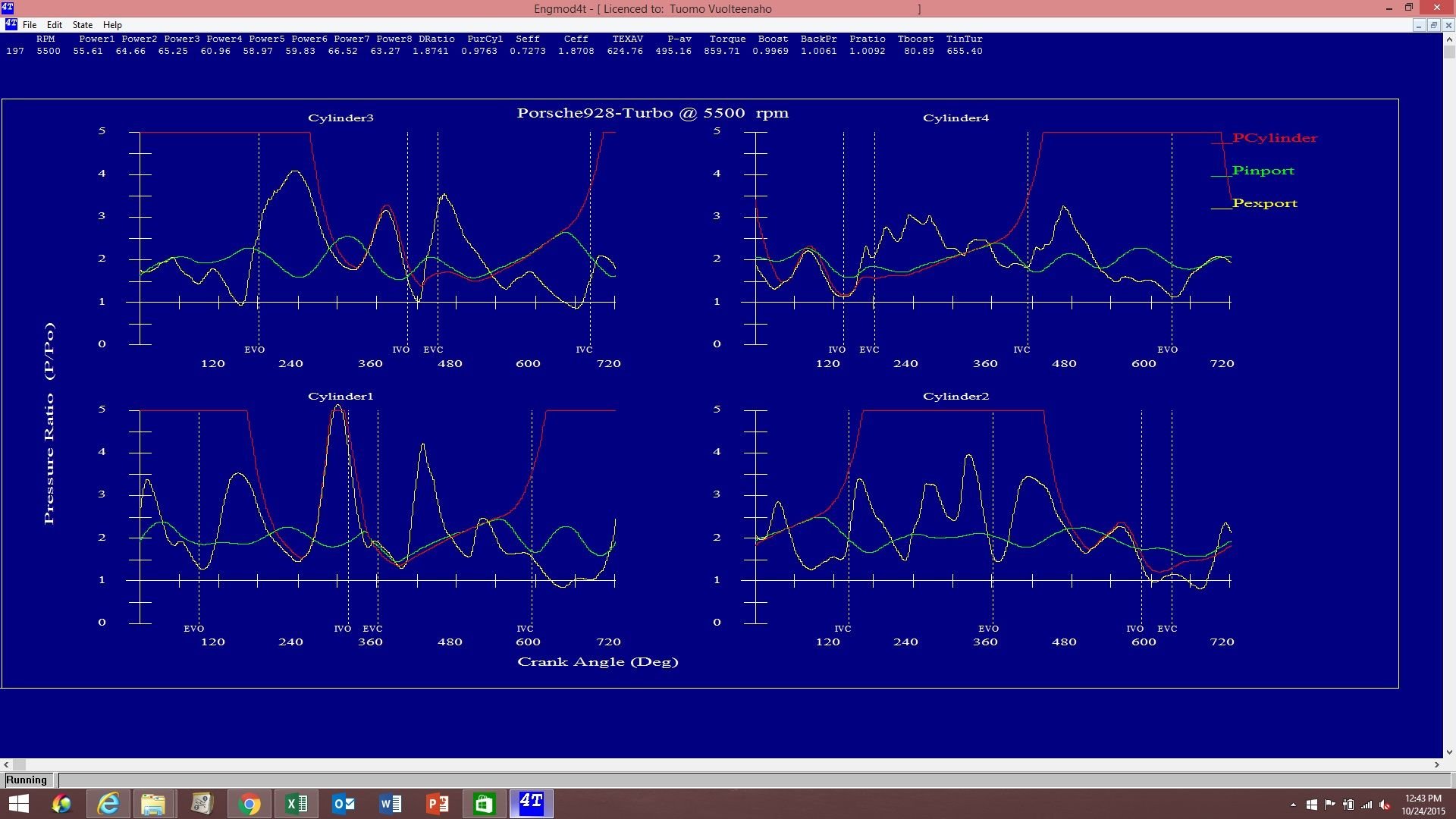
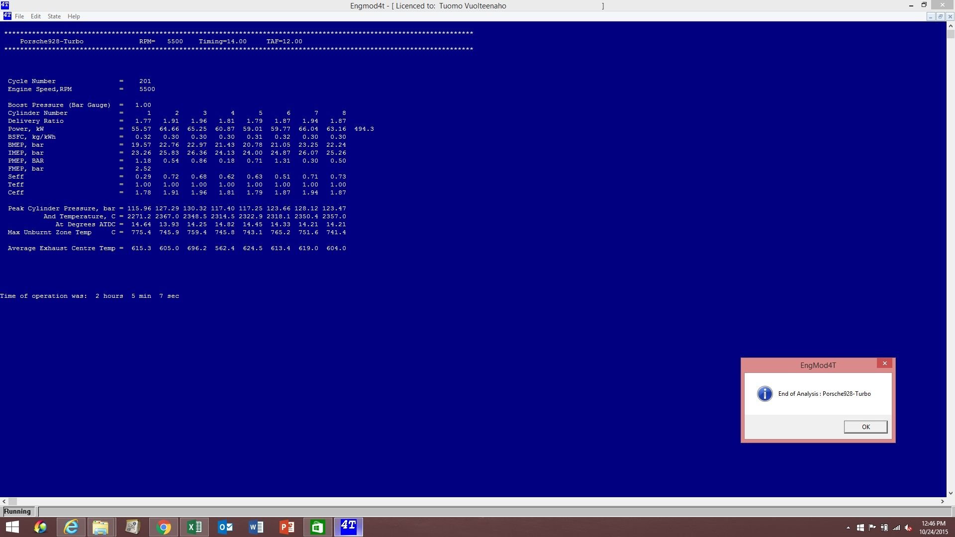
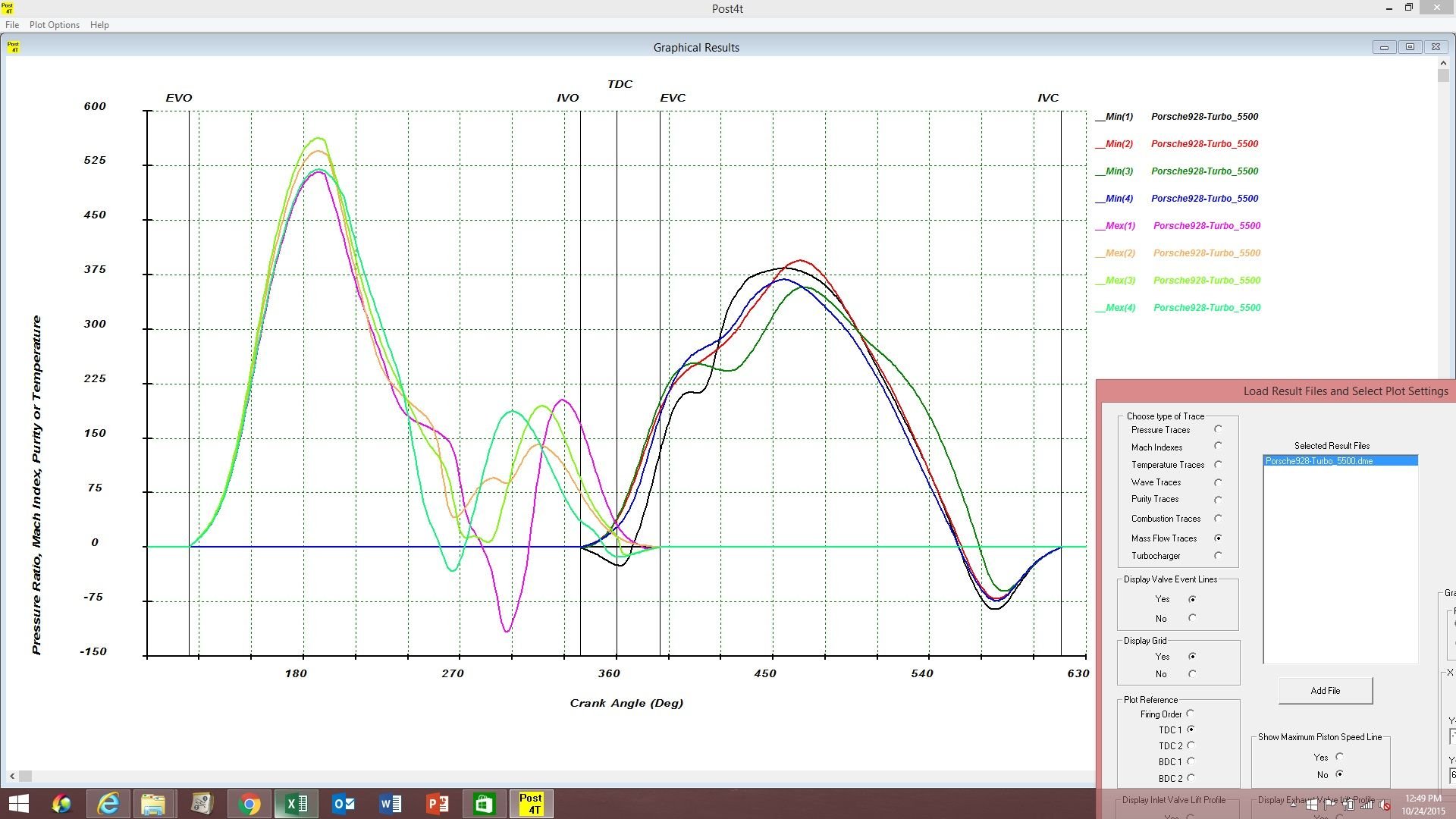
Based on these (now very slow) simulations, the combination of these cast exhaust manifolds, stock S4 intake manifold, gt35r turbine with 84 trim and 0.82 a/r housing, and Elgin 65-6 cams installed 117/111 runs like a champ at 5500 rpm. For better spool early on, we may run it straight up 114/114, though. At one bar, the average boost to average exhaust back pressure ratio is predicted to be almost exactly one, it's withing 1.00-1.05x range. The 90-degree exhaust overlap doesn't quit get delayed long enough at that rpm for the #3 to be able to screw up #1's overlap. Vol-F is low for #1 because the intake starts flowing in the right direction pretty late in the game, but heat is still under control because the exhaust flows out well enough. It'll run very well at that rpm, the model is predicting 660 crank hp at 1 bar boost, which is very nice for such low boost.
Probably the best strategy with these components is to run the torque curve flat at a very high level to 5500 rpm. Then, let the torque drift down after 5500 rpm keeping the power at about constant level up to 7000 rpm. It won't make a huge peak number, but it would make a monster average number. This is how the motor wants to run, so I am thinking why not let the motor run the way it wants to run?
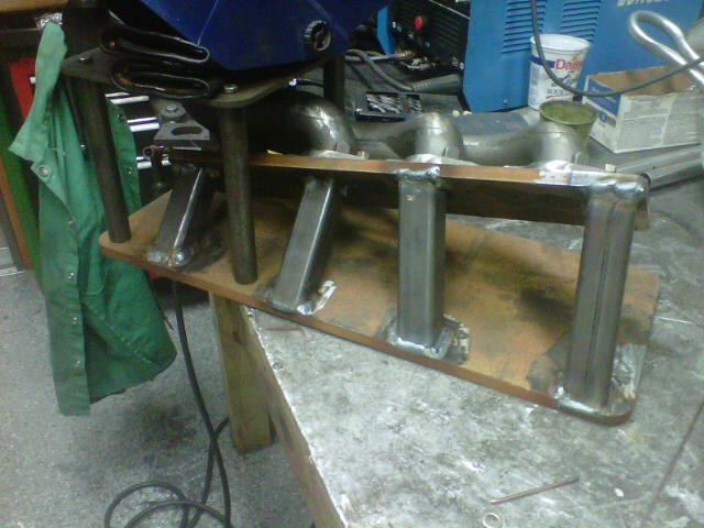
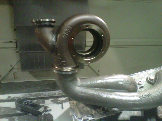
Now, John's got the second fixture and the tools to cut the v-band clamp flange. After that, the manifolds are heading to thermal barrier coating. I've simulated these manifolds a lot, and they will be money at the 5250rpm point where we should hit our peak torque.
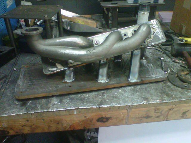
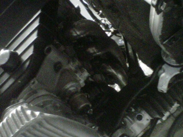
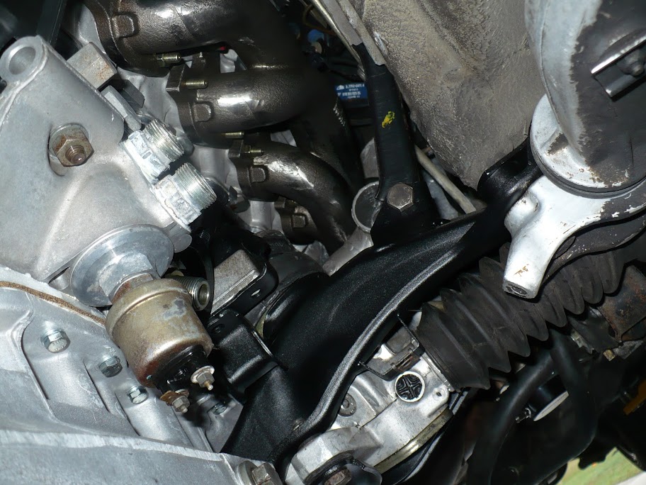
Intense test fitting for the last time before the v-band clamp flanges are machined on the exhaust manifolds. Let's just say that clearances are such that John will only approve of Genuine Porsche motor mounts with his kit. Every effin inch has been spoken for!
Hans has mounts you may be able to raise the engine a few mm with. That could help.
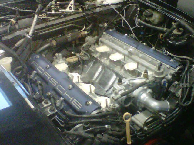
We don't need it too high, we don't need it too low, we need it just right the way the engine sits on genuine Porsche motor mounts. The parts are designed for those mounts. Goldilocks baby Goldilocks...
We don't need it too high, we don't need it too low, we need it just right the way the engine sits on genuine Porsche motor mounts. The parts are designed for those mounts. Goldilocks baby Goldilocks...
That seems the logical thing to design to
Have you designed to allow minimal clearance for worst case scenario of collapsed standard Porsche mounts ... or a proportion of the diminished height?
That seems the logical thing to design to Have you designed to allow minimal clearance for worst case scenario of collapsed standard Porsche mounts ... or a proportion of the diminished height?
John's the designer, not me. I just help along with some (sometimes unsolicited) advice based on the stuff that I can run on the computers.
In any case, yes, the hardware clears the expected range of the motor mounts over their life cycle. There will be some tight spots elsewhere for other components, to be discussed on a later date...
In any case, yes, the hardware clears the expected range of the motor mounts over their life cycle...
I really hope that is true and that there are no expensive bits, bespoke or otherwise, that will be crunched when the mounts drop. At a minimum a canary of some-sort would be useful.
I really hope that is true and that there are no expensive bits, bespoke or otherwise, that will be crunched when the mounts drop. At a minimum a canary of some-sort would be useful.
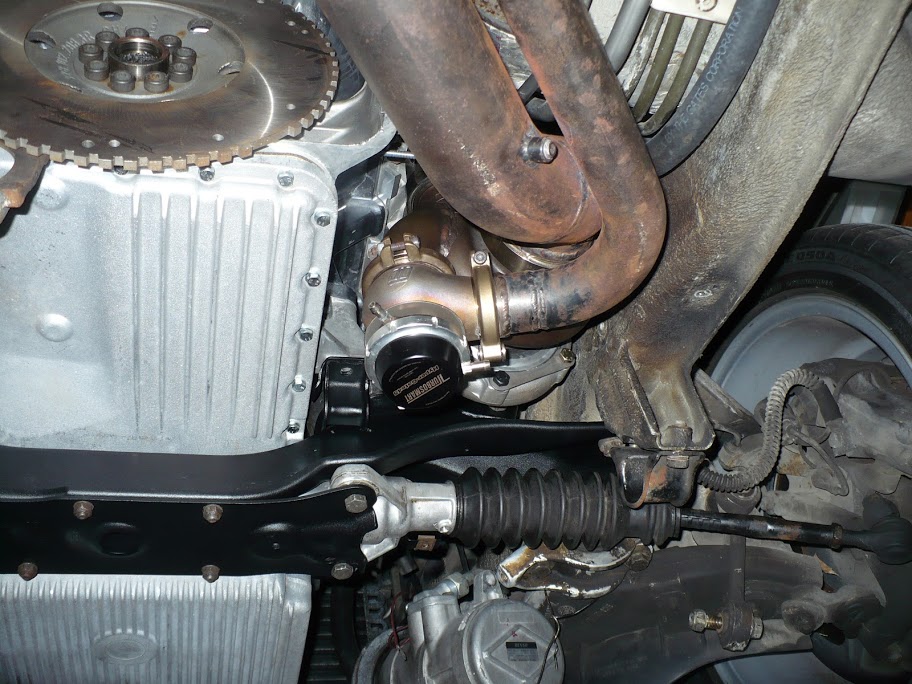
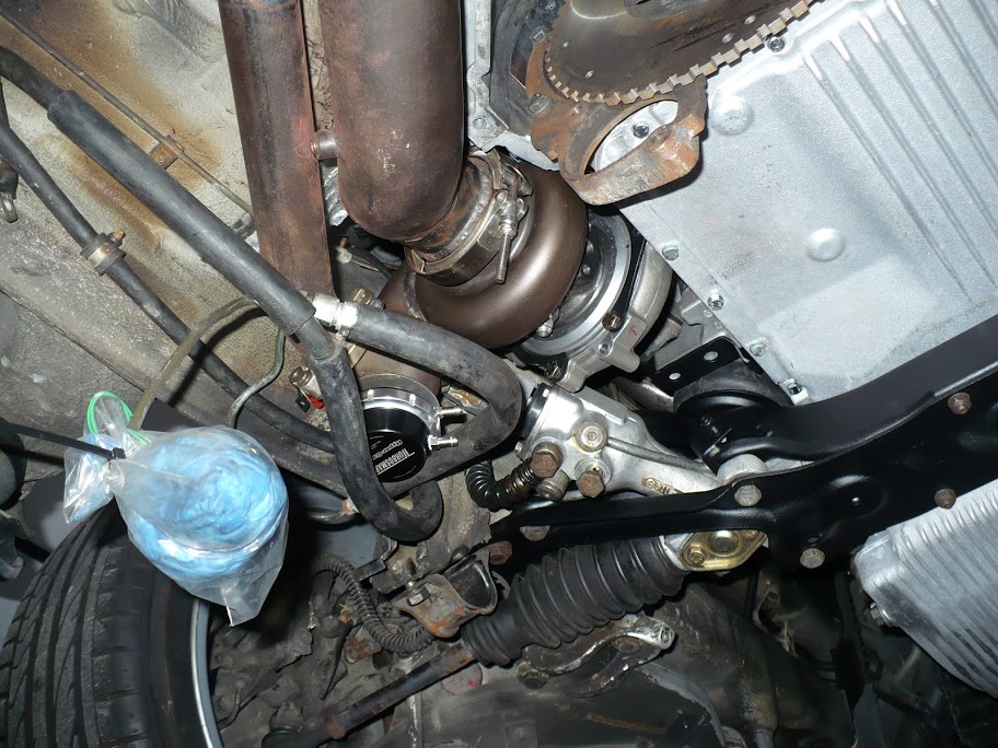
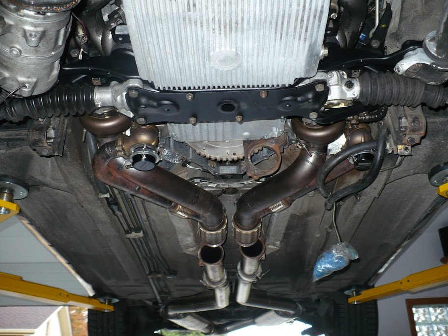
Luckily, the main interference risk is in the case that the engine is installed too high, not if it sags too low. The turbine downpipes would get too close to the frame with motor mounts that install the engine significantly too high.
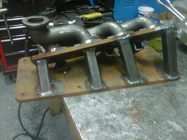
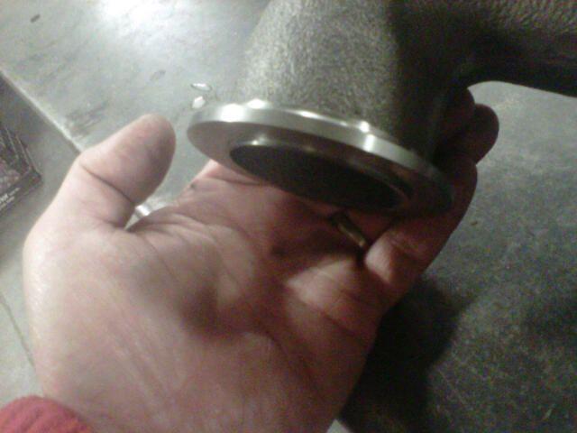
The lip will go into the turbine housing without interference but being snug. It'll guide the flow and work as a sort of a dowel pin. The flat part of the flange is what does the sealing. The 20 degree back cut for the v-band clamp still needs to be cut with the second tool.
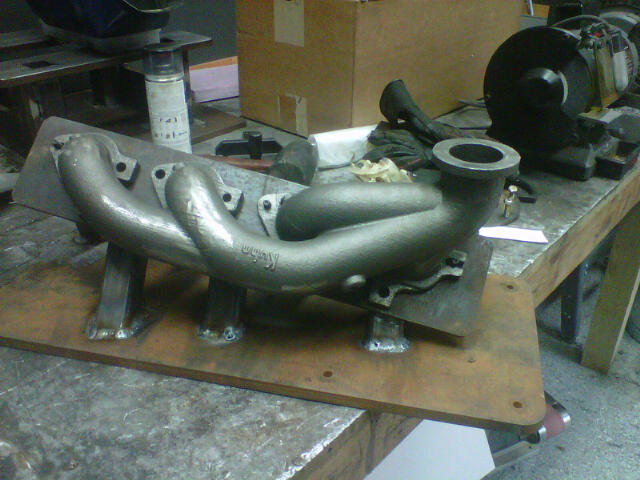
So these manifolds are cast from iron. More specifically, high silicon-molybdenum ductile cast iron, or just "High SiMo" among the friends. It's about 1% molybdenum and 5% silicon, or slightly less. I don't have the exact sheet in front of me.. Addition of moly and silicon to ductile iron increases its "high temperature tensile strength, stress-rupture strength and creep strength." High SiMo castings are cost effective and very durable in applications that frequently see temperatures between 1200-1600F. That's right in the range for exhaust manifolds and turbine housings.
The turbine housing itself is cast from stainless steel. It's cast by Tial so I don't know the exact alloy, but I believe it's 347 or something very close to that. It's very comfortable in 1200-1600F range as well.
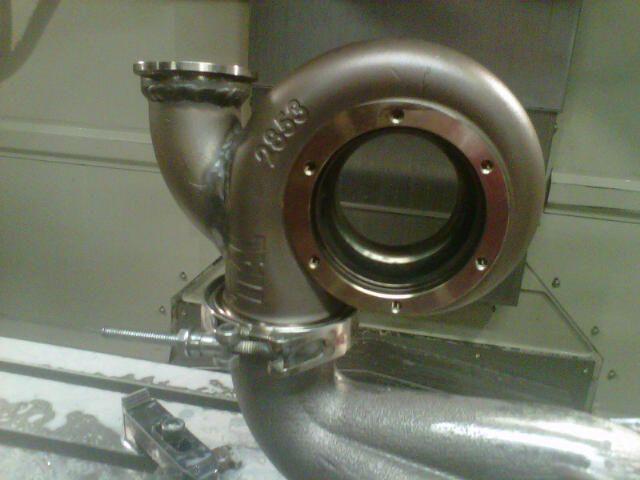
The coefficient of thermal expansion is larger for the turbine housing than for the exhaust manifold, so the lip of the exhaust manifold that slips inside turbine housing isn't going to cause any stresses over the heat cycles. The exhaust manifold having a lower coefficient of thermal expansion helps to put less stress on the head and the manifold itself. The SS turbine housing expands more, but SS is basically the only material that can be used here because it can be cast thin enough so it fits in the space allowed.
The coordinate measuring machine, CAD of the manifolds, and CAM in the casting and machining processes are paying off. The first time in, everything is exactly in the right spot. In terms of the flow path radii and the merge angles, this is about as well you can do without modifying the frame. Also see how good (within reason, what I really mean is look at how much less it sucks) the access is to the exhaust manifold studs.


 10-19-2015, 05:43 PM