When you click on links to various merchants on this site and make a purchase, this can result in this site earning a commission. Affiliate programs and affiliations include, but are not limited to, the eBay Partner Network.
LOVE IT ! I'd just read my way through several pages of children bickering about how to build a better NA inlet manifold, got well sick of that. So searched out this thread to see where you were up to, LOL no BS here just get on and make sweeet horsepower ! Getting excited to see what numbers this will push out......Looking fabulous
I'm usually on of those children! I do like to think about stuff like that, how to either improve the stock S4 manifold or how to make a replacement. One thing that'll be interesting about this iteration of the turbo project is whether the stock intake manifold will end up being a bottle neck or not.
LOVE IT ! I'd just read my way through several pages of children bickering about how to build a better NA inlet manifold, got well sick of that. So searched out this thread to see where you were up to, LOL no BS here just get on and make sweeet horsepower !
Getting excited to see what numbers this will push out......Looking fabulous
With all that has been said and found by for-bearers like Todd, I think its a moot point, don't you? Bottlenecks are relative, in this case its relative to the efficiency of the rest of the system and the goals of the package. Since the engine needs air and fuel to run (and spark), and the intake is the air part.....
Those are some professionally looking manifolds. Well done! Any plan to run heat shields on them to keep the chassis paint intact?
What part of the chassis are you concerned about?
The thermal barrier coating protects the surrounding areas well. That we know from the last couple of years and several cars running these turbo systems with coated manifolds. I am also directing air flow to that area much the same way that the factory is to protect, among other things, the motor mounts.
There will be additional heat shields to protect the seals, however. I was recently educated about the problems that 944 Turbos have with the pressure side of the exhaust header and the wastegate circuit causing the oil pan seals to overheat. Although we haven't had any such problems in the past, this version will have small heat shields protecting the oil pan and the valve cover gasket in the areas that are close to the pressure side of the exhaust manifold. That's just insurance.
With all that has been said and found by for-bearers like Todd, I think its a moot point, don't you? Bottlenecks are relative, in this case its relative to the efficiency of the rest of the system and the goals of the package. Since the engine needs air and fuel to run (and spark), and the intake is the air part.....
Are you referring to the stock S4 intake manifold? Do we know whether a short runner single plenum manifold or the long runner active resonance manifold is better for a turbo car?
The thermal barrier coating protects the surrounding areas well. That we know from the last couple of years and several cars running these turbo systems with coated manifolds. I am also directing air flow to that area much the same way that the factory is to protect, among other things, the motor mounts.
There will be additional heat shields to protect the seals, however. I was recently educated about the problems that 944 Turbos have with the pressure side of the exhaust header and the wastegate circuit causing the oil pan seals to overheat. Although we haven't had any such problems in the past, this version will have small heat shields protecting the oil pan and the valve cover gasket in the areas that are close to the pressure side of the exhaust manifold. That's just insurance.
I was referring to the second last picture but you've answered my question. Thanks.
We're working on a new kind of crankcase breather system for boosted cars that we believe will fix some of the issues that the 928 S4 has. We considered all operating modes one by one and the pressures and external forces associated with each of them. We think our solution will work in all operating modes.
Since we'll be feeding the crankcase gasses to the intake, we need a check valve in the line from the crankcase and the charcoal canister to the intake manifold. Got the check valve and John will be fabricating the rest of the parts shortly.
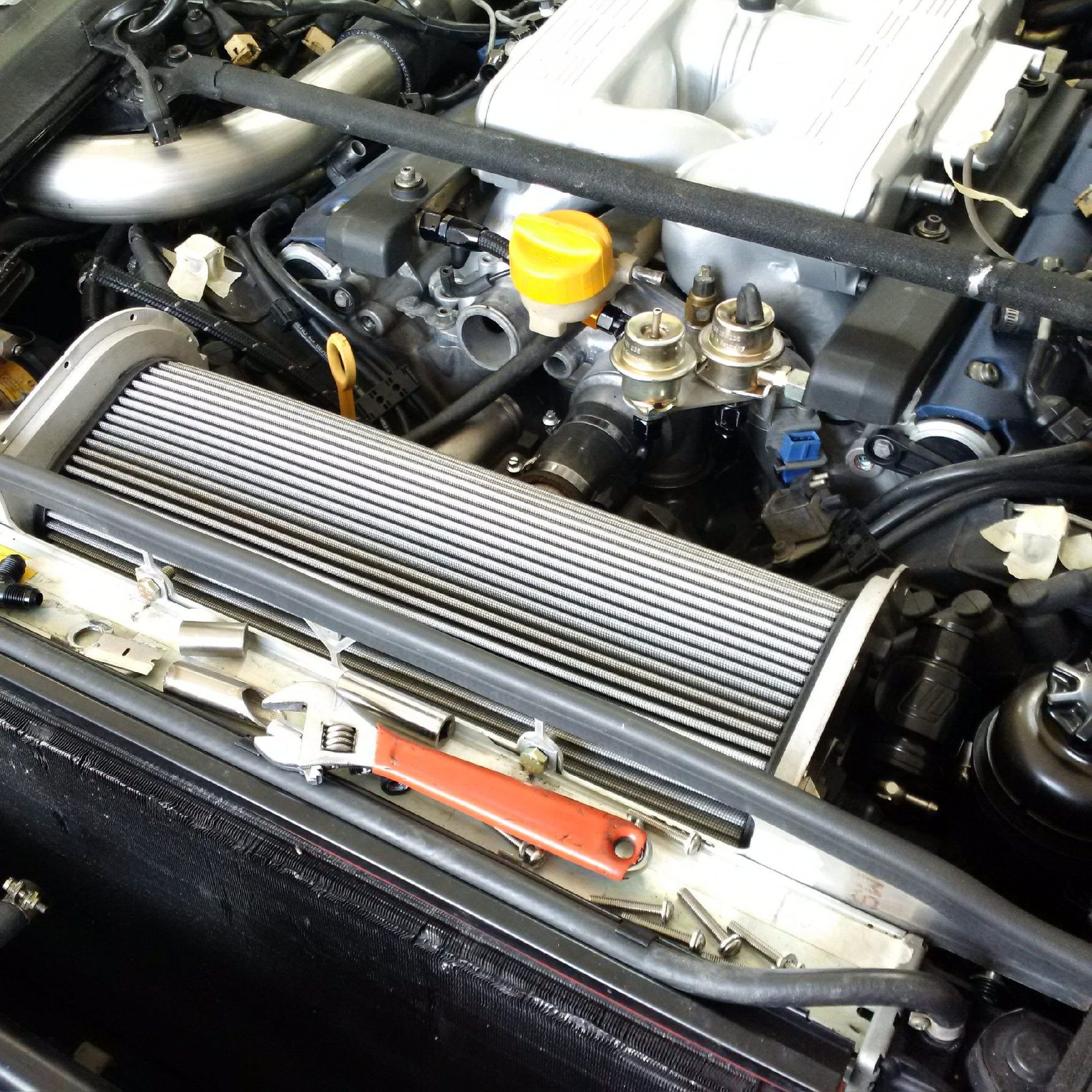
We'll have to fit two 3/4 inch hoses from the filler neck to the separators, one per side. The bmw separators will be located on top of the turbo oil sumps. So the hoses need to curve back and to the sides, preferably without kinks and in an aesthetically pleasing way.
We're working on a new kind of crankcase breather system for boosted cars that we believe will fix some of the issues that the 928 S4 has. We considered all operating modes one by one and the pressures and external forces associated with each of them. We think our solution will work in all operating modes.
Since we'll be feeding the crankcase gasses to the intake, we need a check valve in the line from the crankcase and the charcoal canister to the intake manifold. Got the check valve and John will be fabricating the rest of the parts shortly.
We'll have to fit two 3/4 inch hoses from the filler neck to the separators, one per side. The bmw separators will be located on top of the turbo oil sumps. So the hoses need to curve back and to the sides, preferably without kinks and in an aesthetically pleasing way.
With the kind of power you'll likely be making, are you sure a 3/4" hole to vent the crankcase will be enough? I remember doing a crap-ton of calculation on this when I was trying to figure it out on the GT. If memory serves, 1 single 1/2" hole will about 600HP (500WHP). I never took it up to the levels you're planning. My gut says it should be okay, but the amount of air required to get up to your level may overwhelm that 3/4" hole.
I can tell you, based on what happened to the PO of my 85 Euro, if the breather is not sized properly, of if poorly designed, it's like giving your car coronary artery disease. The pressure in the crankcase will just continue to build, and if it cannot escape... your car with have a heart attack and it'll go boom. That's what happened to the guy who had the Erup before me. I fixed it, but it required me to replace the block. All is good now.
As pointed out above, it's 2x3/4" ports.
The approximate math that takes you to the ballpark is fairly straightforward. Suppose you want to make 1000 hp at the wheels, purely hypothetically. You'll need about 1700 scfm to do that. A good engine that's designed, built and broken in correctly will pass say 1% of that in blow by, a poorly built or broken in will pass say 3%. The worst case scenario is thus 51 scfm of blow by. Using two 0.75 orifices with 0.7 discharge coefficients, you'll see a 0.45 psi pressure in the crankcase in the worst case scenario. In the best case scenario, you'll see only about 1/9 (this is an approximation) of that pressure. The required breather hose diameter goes up about one for one with the blow by percentage.
The moral of the story is that poorly built, designed, or broken in, or excessively worn engine is going to struggle even with a huge breather. A good engine can do with a modest size breather. I'm hoping that we see very little blow by and that 2x0.75" is grossly oversized. If it's not enough, we're f$&c@ed anyway for a number of other reasons because the engine isn't sealing at the rings.
Managing the air oil separation, oil flow in the crankcase, and air flow in the crankcase in all operating modes is a much more interesting and challenging problem than just sizing the breather hoses. Those are the topics we spent most of our brain cycles on.
The approximate math that takes you to the ballpark is fairly straightforward. Suppose you want to make 1000 hp at the wheels, purely hypothetically. You'll need about 1700 scfm to do that. A good engine that's designed, built and broken in correctly will pass say 1% of that in blow by, a poorly built or broken in will pass say 3%. The worst case scenario is thus 51 scfm of blow by. Using two 0.75 orifices with 0.7 discharge coefficients, you'll see a 0.45 psi pressure in the crankcase in the worst case scenario. In the best case scenario, you'll see only about 1/9 (this is an approximation) of that pressure. The required breather hose diameter goes up about one for one with the blow by percentage.
...
They told me there wouldn't be any math... More seriously, thanks for the technical explanation. I find the engineering fascinating.
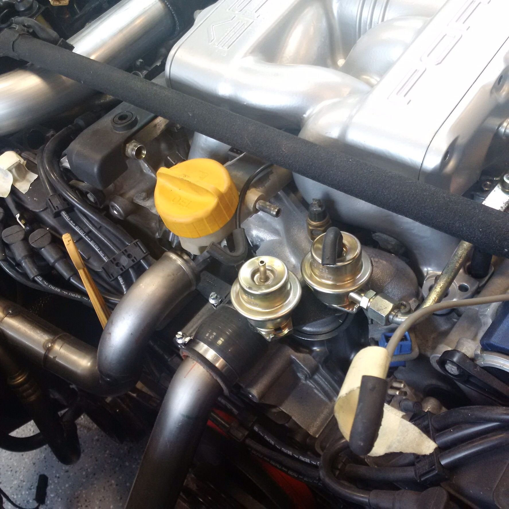
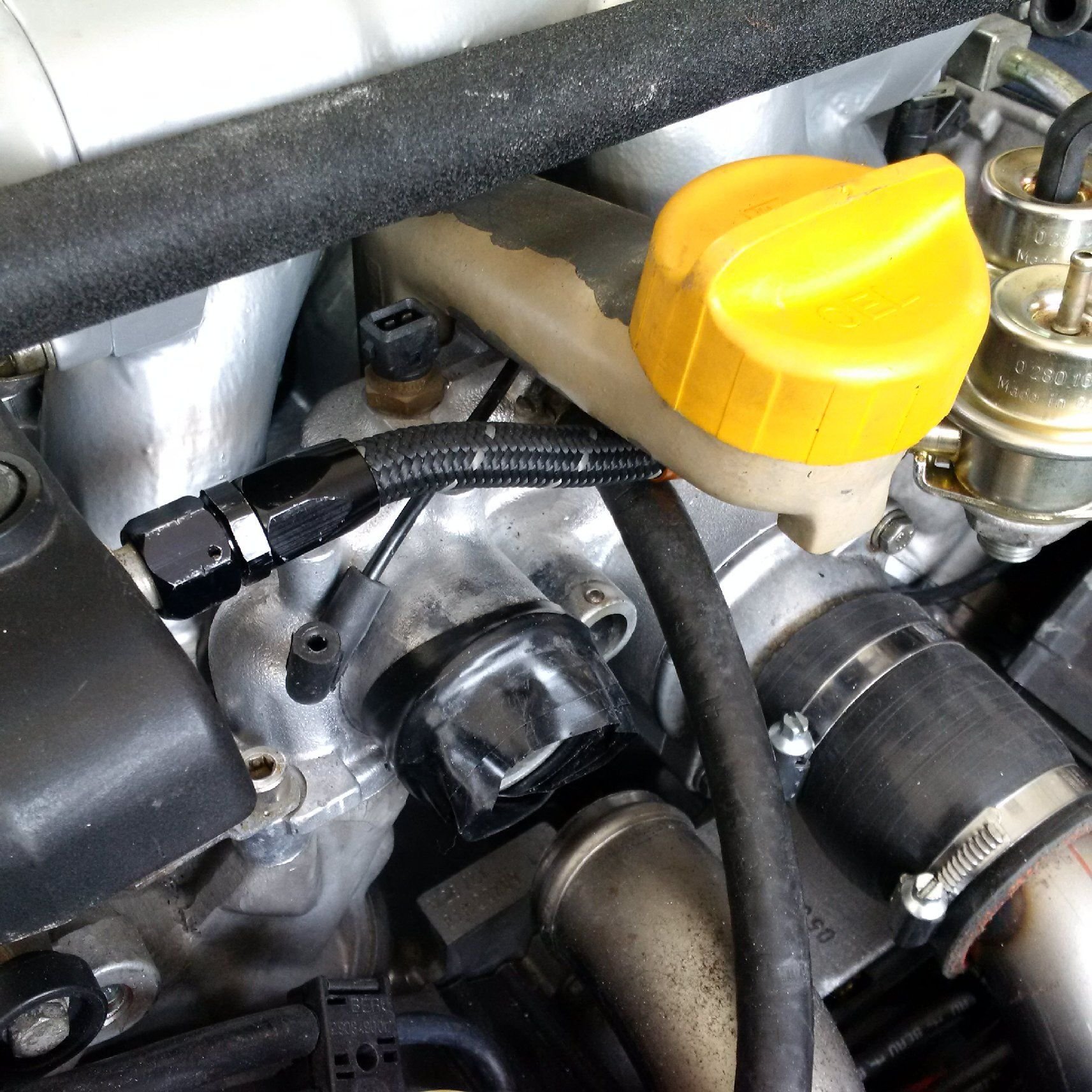
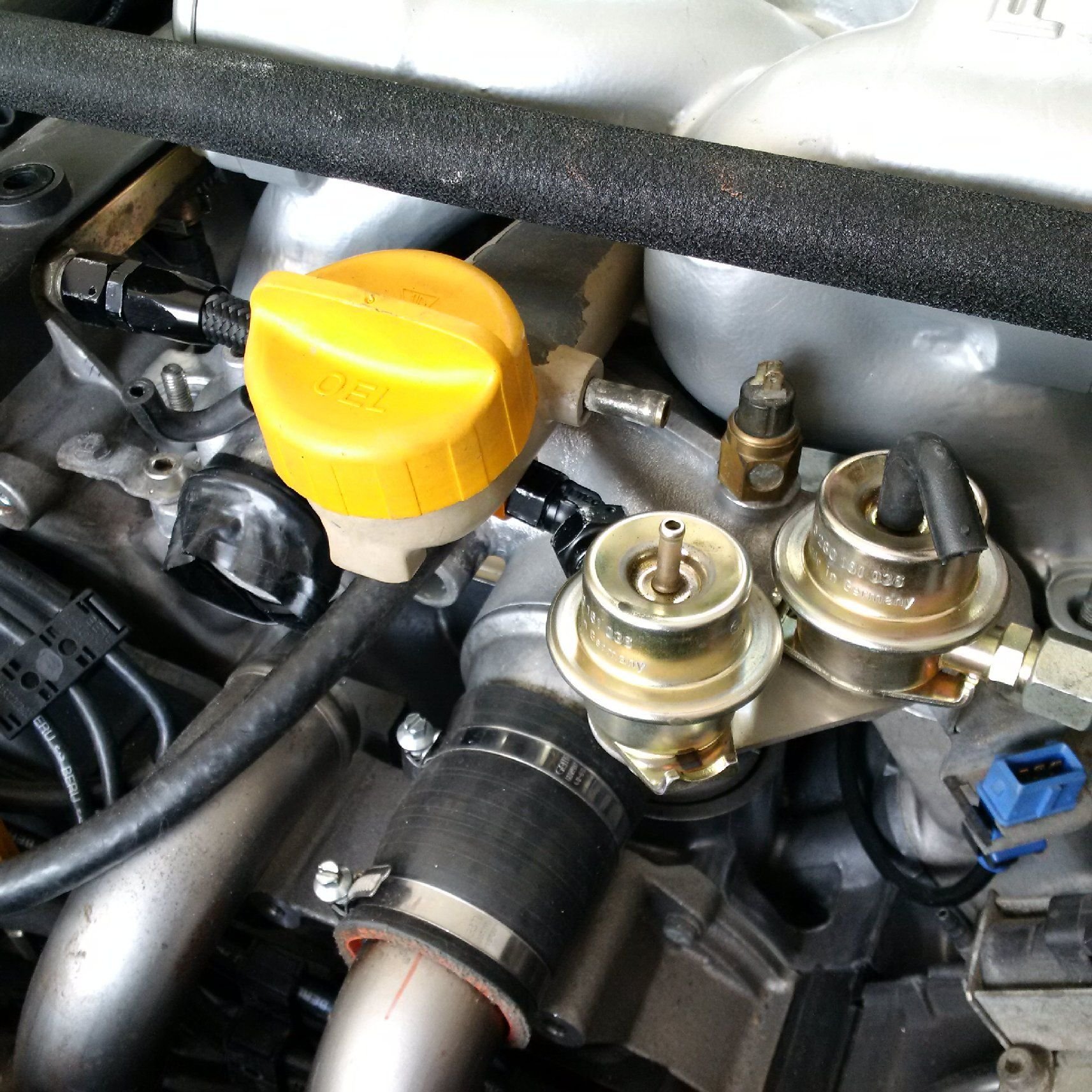
One thing to keep in mind is that running those 3/4" hoses to the separators takes a lot of space. The one thing that possibly conflicts with the optimal breather hose pickups is the fuel dampers. Since we're running batch fire with big injectors, we need those additional fuel dampers. They are essential to smooth out resonances at these fuel flow levels. All those things will have to clear each other's:
The idea is to have the breather ports come off sideways from the filler neck, parallel to the chassis support bar/brace. Since our configuration doesn't use the small 2mm restrictor nipple, the best location for the driver side port would be replacing that nipple.
Problems with the stock external crankcase breather system
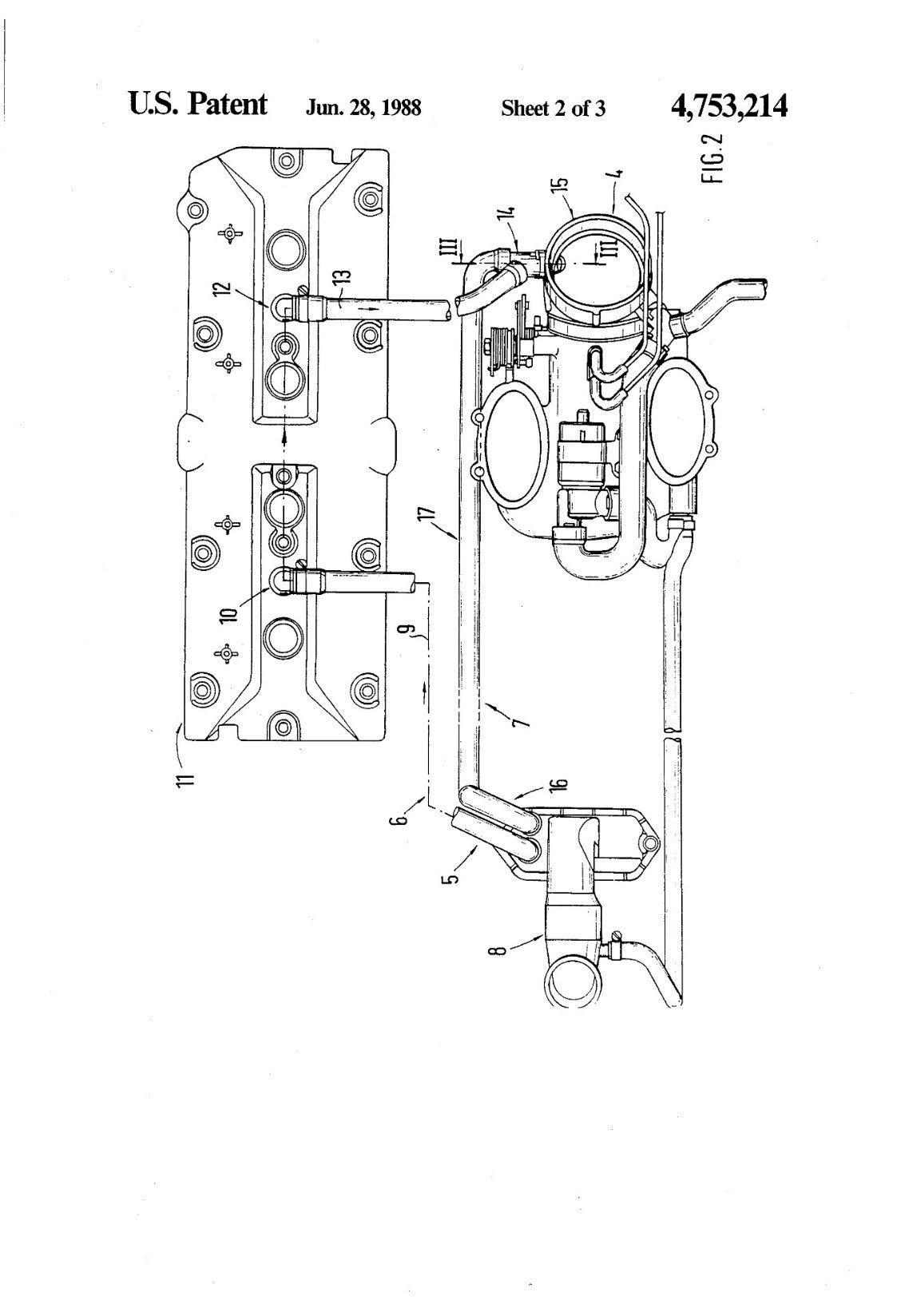
The post-1987 Porsche 928 models have had a number of different kinds of crankcase breather systems installed from the factory. The original conceptual design is described in the US Patent 4,753,214. Figure below is sourced from the patent documents:
There are a number of important features in this original concept. The rear passenger valve cover breather (patent figure 12) has a volume separator inside the valve cover (not displayed in the drawing) and approximately 6mm metering orifice in the elbow. The connection (patent figure 16, 7, 17) has a check valve with approximately 1-1.5 psi cracking pressure. The from passenger valve cover breather (patent figure 10, 9, 6, 5) has no separator and no metering orifice. The connection from the oil filler neck to the intake manifold plenum has an approximately 2mm metering orifice.
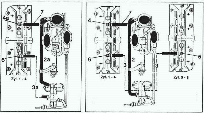
Subsequently, multiple different variations of this system were produced. The two later ones are describes in the below figure from the workshop manual:
While the implementation in the early GTS engines on the left is more faithful to the original concept, the implementation on the right for the later GTS engines deviated significantly from the original concept. A connection between valve covers is added, a check valve is eliminated, etc. The GTS engine breather system is broadly considered a failure, but it is not clear whether this is because of the external breather system per se or some other, more fundamental problems with the engine design.
The early S4 crankcase breather system that closely corresponds to the system originally described in the patent documents works somewhat adequately if the engine, including the engine redline, is stock and if the car is run on stock tires at moderate lateral accelerations. If the engine rpm is increased or other changes made, problems often appear. Subsequent GT models had more serious problems in even their stock form.
The lateral accelerations are relevant for the following reasons. In a 90-degree V8 engine, the oil drains from the cylinder heads are in approximately 45-degree angle relative to the vertical plane. In a 1g lateral acceleration, from the oil drain perspective the engine is effectively turned sideways with the oil drains horizontal on the outside turn bank of the engine. In this situation, there is no gravity drain, and the pressure differential between the crankcase and the head mostly determines in which direction the oil flows. If the crankcase pressurizes and the heads are relieved, it is logical to assume that the oil will flow into the heads instead of the sump.
In addition, the piston pumping pulses create havoc in the oil drains. It is possible that if blow by gasses increase the pressure and density of the crankcase and high rpms then increase the energy delivered by the piston pumping pulses, the oil may be ejected from the oil drains into the heads. The combination of high blow by rates, high engine speeds, and relatively low pressure in the heads compared to the crankcase may lead to oil drain problems so significant that the oil pump pickup in the sump will be starved of oil, resulting in engine failure.
I believe that the GT and S4 models� crankcase breathing problems can be mostly resolved by redesigning the external crankcase breather system. Higher the operating rpms and higher the lateral accelerations, more extensive the required internal engine modifications. However, the engine internals of GT and S4 models are adequate for most uses, while improvement are of course possible.
The GTS engine has many issues relating to oil consumption and crankcase breathing, and I believe those aren't caused mainly by the breather system and in any case can't be cured with minor tweaks of the stock breather system. I believe that one problem in the GTS engine is the crankshaft. First, the increased stroke increases the pumping pulse energy by about 18.5% based on a crude back of the envelope formula. Second, the GTS crankshaft counterweights are very poorly designed. They not only cause high bearing loads but also block the crankcase gas flow with the addition of the center counterweights and the large fan angles of the counterweights. Finally, at least some GTS pistons do not have sensible oil drain provisions, leading to poor oil control on the bore walls and significant blow by that may be impossible to resolve with an external breather system. This combination leads to a situation in which crankcase is pressurized by blow by, oil is ejected to the intake manifold, the ejected oil will cause detonation, detonation will cause increased blow by, etc.
For a number of reasons, we need to design a new crankcase breather system for the 928 engine. The system will have to meet the following requirements:
1. The system has to accommodate turbocharged use.
2. The system has to be fully closed in that the blow by gas is vented into the intake tract, or easily adapted to function in that way.
3. The system has to facilitate adequate oil drain from the heads into oil sump.
4. The system has to be compatible with pressure side MAF sensor location without fouling the MAF sensor hot wire. Fortunately, the stock MAF sensor incorporates a burn-off cycle which makes this particular MAF sensor less sensitive to minor fouling.
5. The system has to be easily adaptable to draw-thru MAF conversion.
6. The system has to result in a consistent amount of air ingested by the cylinders in each ECU load cell (per rpm per MAF sensor reading). Some unmetered gas may be circulated into the system and some metered gas may be circulated out of the system, as long as the amount of fuel and air ingested by the cylinder will remain consistent in each ECU load cell.


 03-10-2016, 05:59 AM