When you click on links to various merchants on this site and make a purchase, this can result in this site earning a commission. Affiliate programs and affiliations include, but are not limited to, the eBay Partner Network.
John's been working on a new air filter box design for a little while now.
Although the old air filter system with its lobster-claw look was just right for the old system, and kind of bad-a$$ looking while doing its job, it was designed for lower power levels that we are after now. (Furthermore, there was some business related issues with "knock offs" appearing: http://www.kuhnperformance.com/tech-talk/wall-shame . But who cares in the long run since if you keep developing and innovating it'll all be water under the bridge.)
What we need now is flow capacity that is about 50% more than the old system. We need 50% more surface area on the filter element and that doesn't fit in the old location. Furthermore, we need more room between the radiator and the cam belt plane to fit in dual 3.5" inch pipes. 3" would give us a flow velocity of 0.23 Mach, which would be fine without turns. 3.5" gives us the margin of safety to put in couplers and bends into the flow path and still have only minimal minor loss coefficient. Static pressure will drop proportional to the square of the velocity, but as long as it doesn't drop more, there's no efficiency loss.
There's a cascading effect of all these changes, but now there's a solution. Furthermore, it's not much more expensive to fabricate than the old system. All in all, the materials cost is going up but labor cost is going down as he's "plus sizing" the system.
What remains to be designed and/or fabricated:
- The air box cover to go with the metal frame
- Integration of the inlet pipes to the air filter
- Integration of the two external air-oil separators to the air box cover
Some progress photos below.
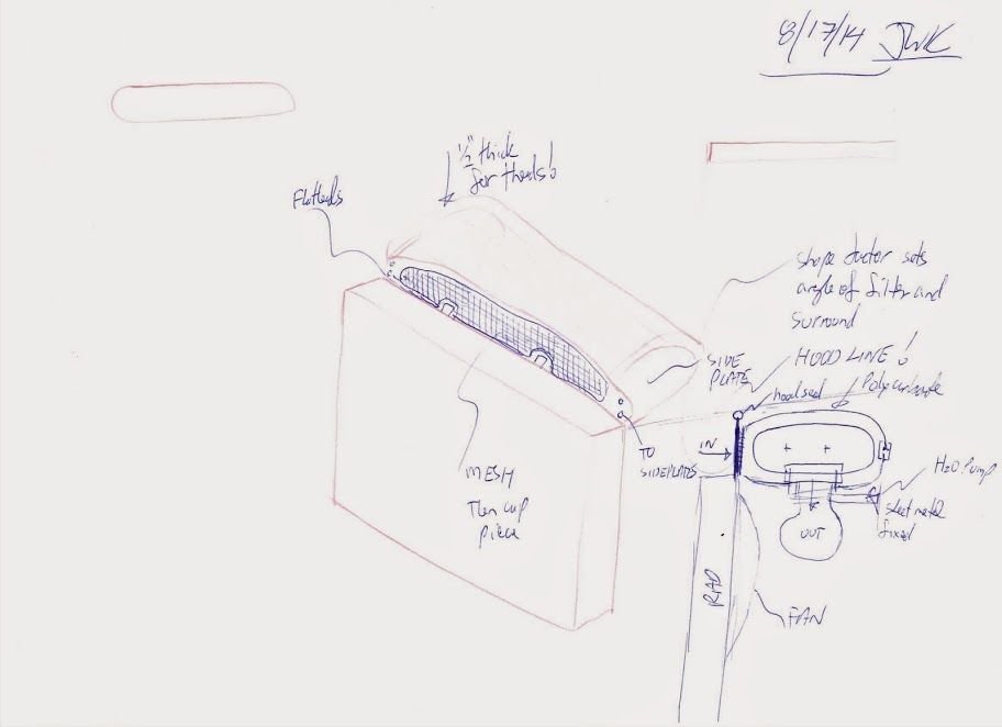
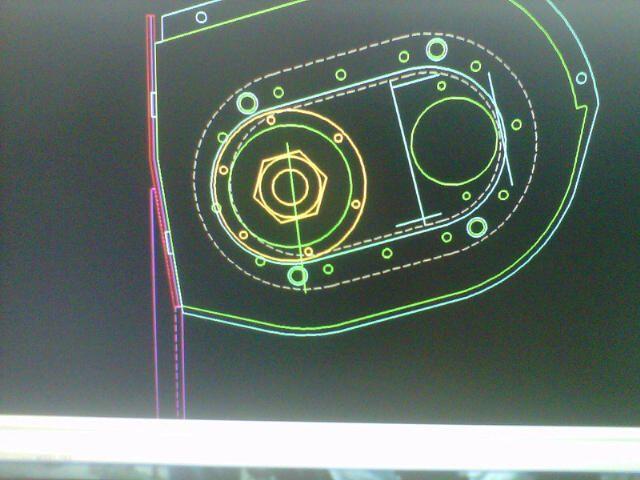
Sketches:
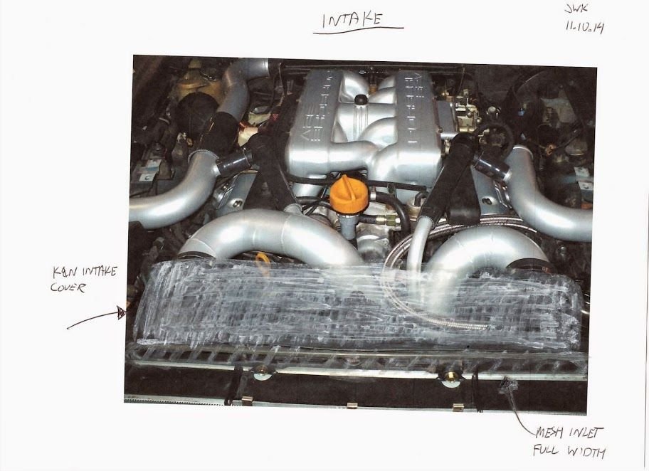
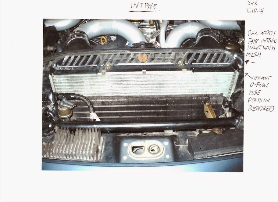
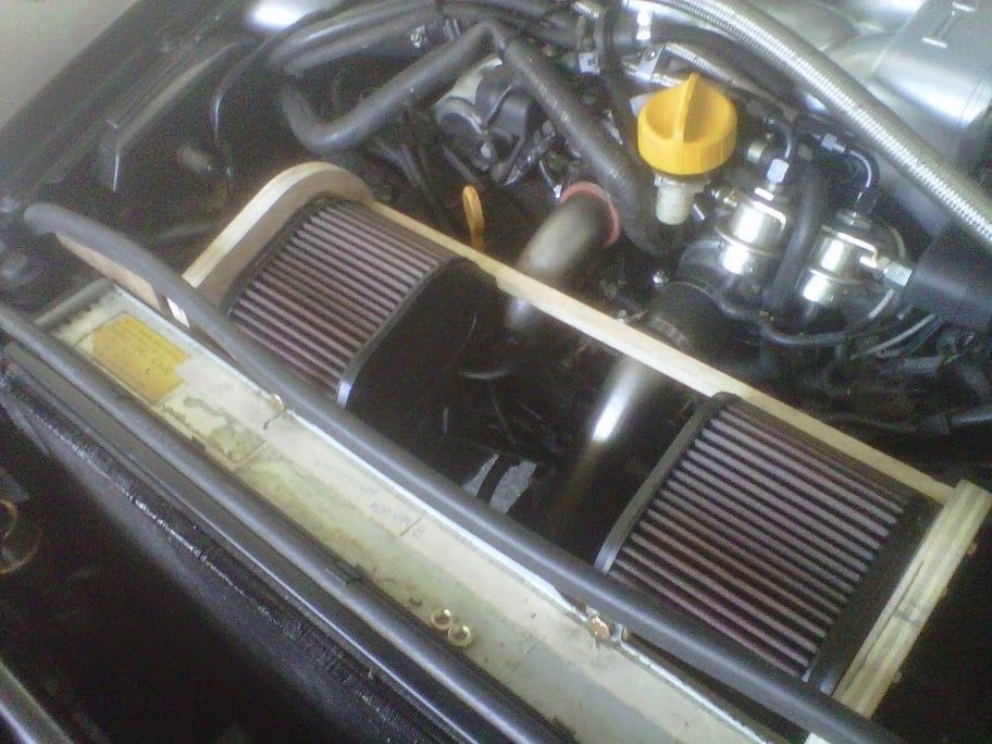
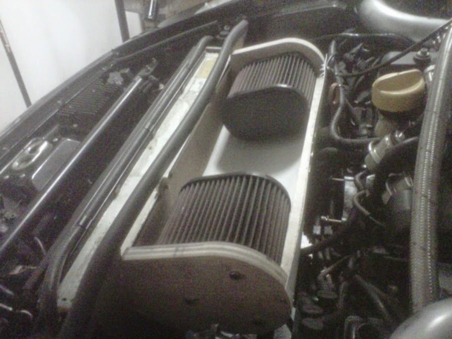
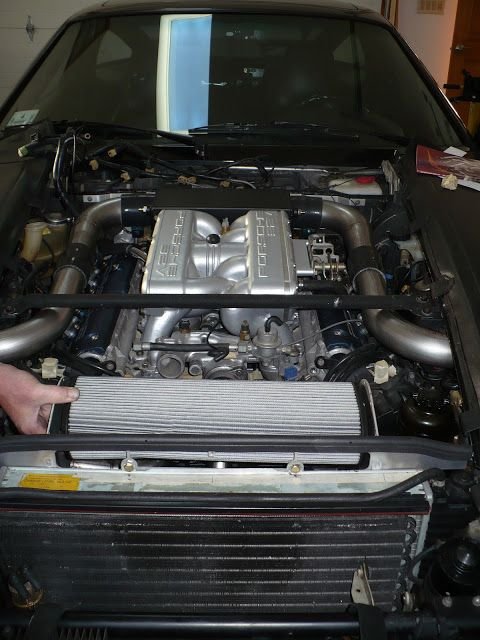
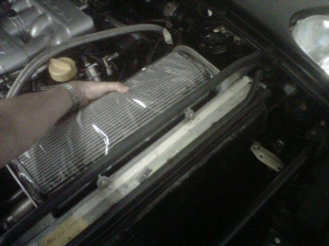
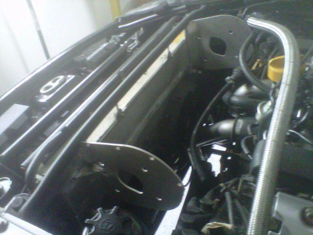
Mockups with the old filters and wooden box:
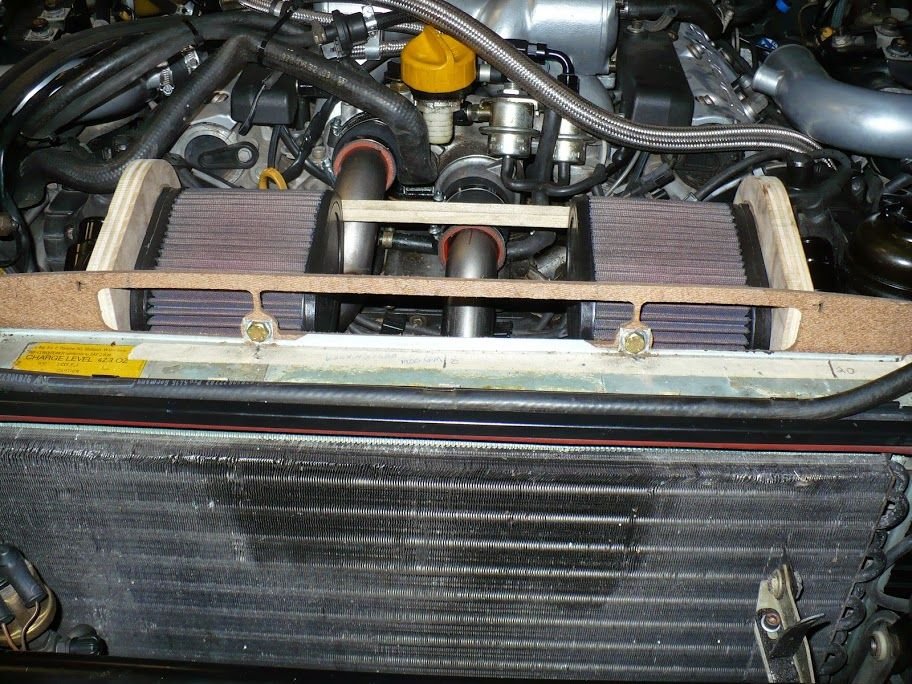
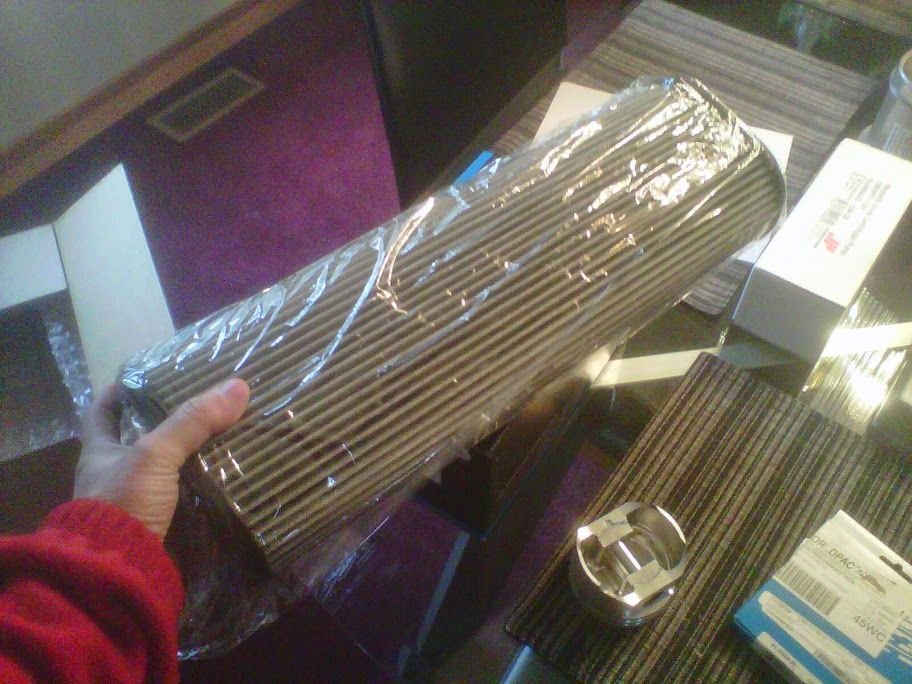
Metal box frame and the actual high-capacity filter:
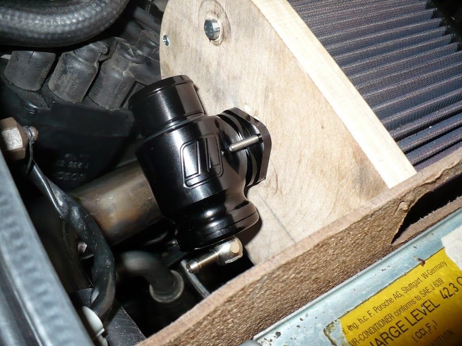
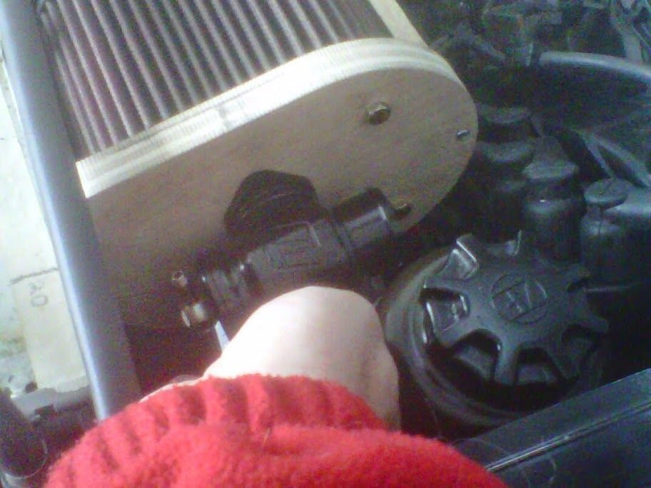
There air filtering setup for this new system is going to be pretty interesting. It will be a little bit harder for others to knock off than the old system. The bypass valves will be integrated to the air filtering system and connect to the first bend coming out of the intercoolers. The cutouts for the compressor bypass valves are larger now at 1.25" and they will slice off the outside of the 2.5" tube and then curve straight forward to hit the compressor bypass valves in the filter body. The flow capacity of the filter system will be massive, something that can't run thru the stock radiator shroud element.
I'm curious, why are you filtering the air after the intercoolers rather than before? I would think having grit-laden air being forced through tight spaces would be a cause for concern.
Edit: It appears I misread where the filter sill be located in relation to the rest of the system. It's the bypass valve that is connected after the intercooler. Sorry for my misreading.
Yes. The air that goes into the compressor will be filtered.
The bypass valve could be connected to the pressure side either before or after the intercooler. Both have positives and negatives. If the intercoolers have a lot of capacity, then after the intercooler makes more sense. Suppose that the intercooler works at 100% efficiency in the limit. The charge air is now always ambient temperature. Now, feeding it to the intake side of the compressor causes the air to expand and the pressure to drop. This results in a below-ambient compressor inlet air temperature, which is beneficial. If however the intercooler has limited capacity, then one is better off relieving the pressure upstream of the intercooler.
In our case, the above considerations had about nothing to do with the plumbing decisions, which were 100% driven by packaging considerations.
A lot of new stuff will be tested in this iteration.
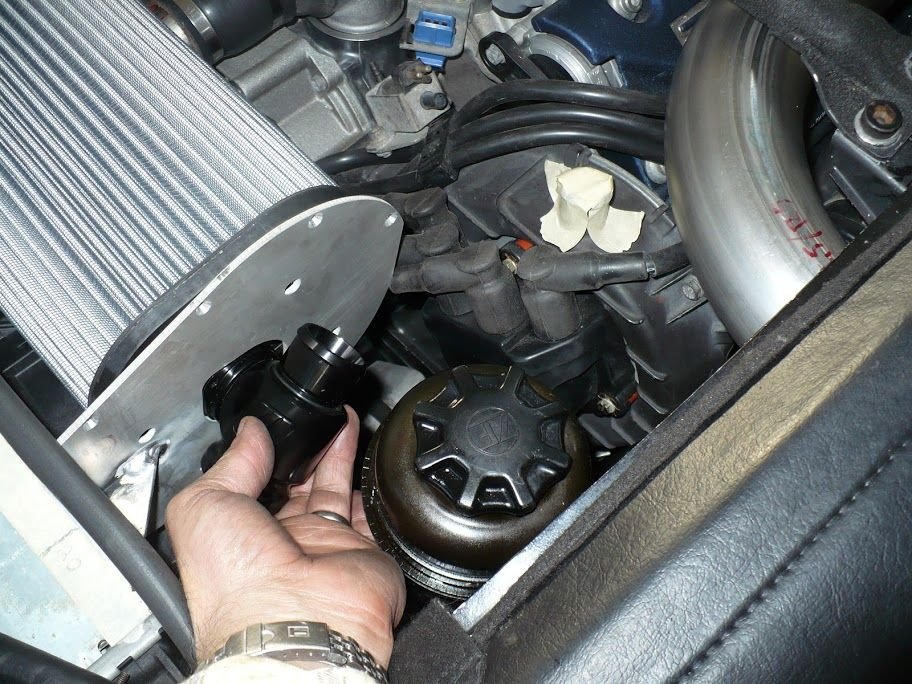
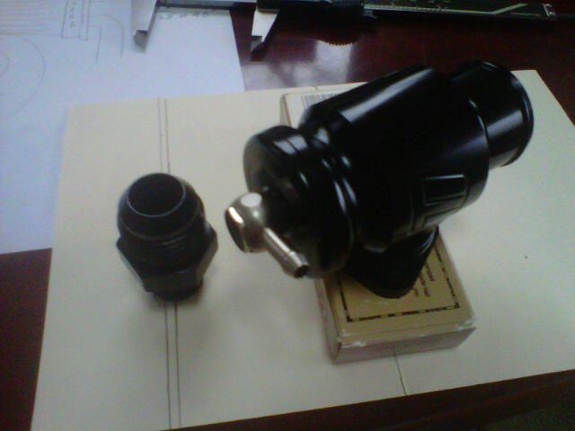
One of the new things is these BMW air-oil separators as the secondary separators, two units needed in parallel given the range of possible blowby flow rates:
This is where the BMW secondary separators will likely be mounted. This will give oil a straight shot drain path to the turbo oil sumps, which are actively scavenged by an external pump.
There will be two 3/4" hoses coming in and out, the hose length itself at that diameter will achieve some separation.
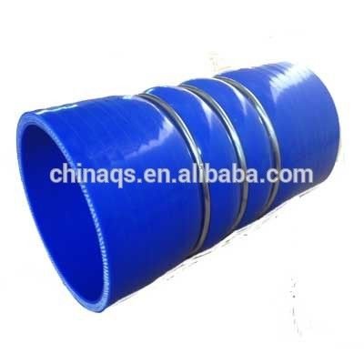
is it possible to get rid of the silicon connector and weld those two intake pipes together? once painted/coated those charge pipes would look awesome without it.
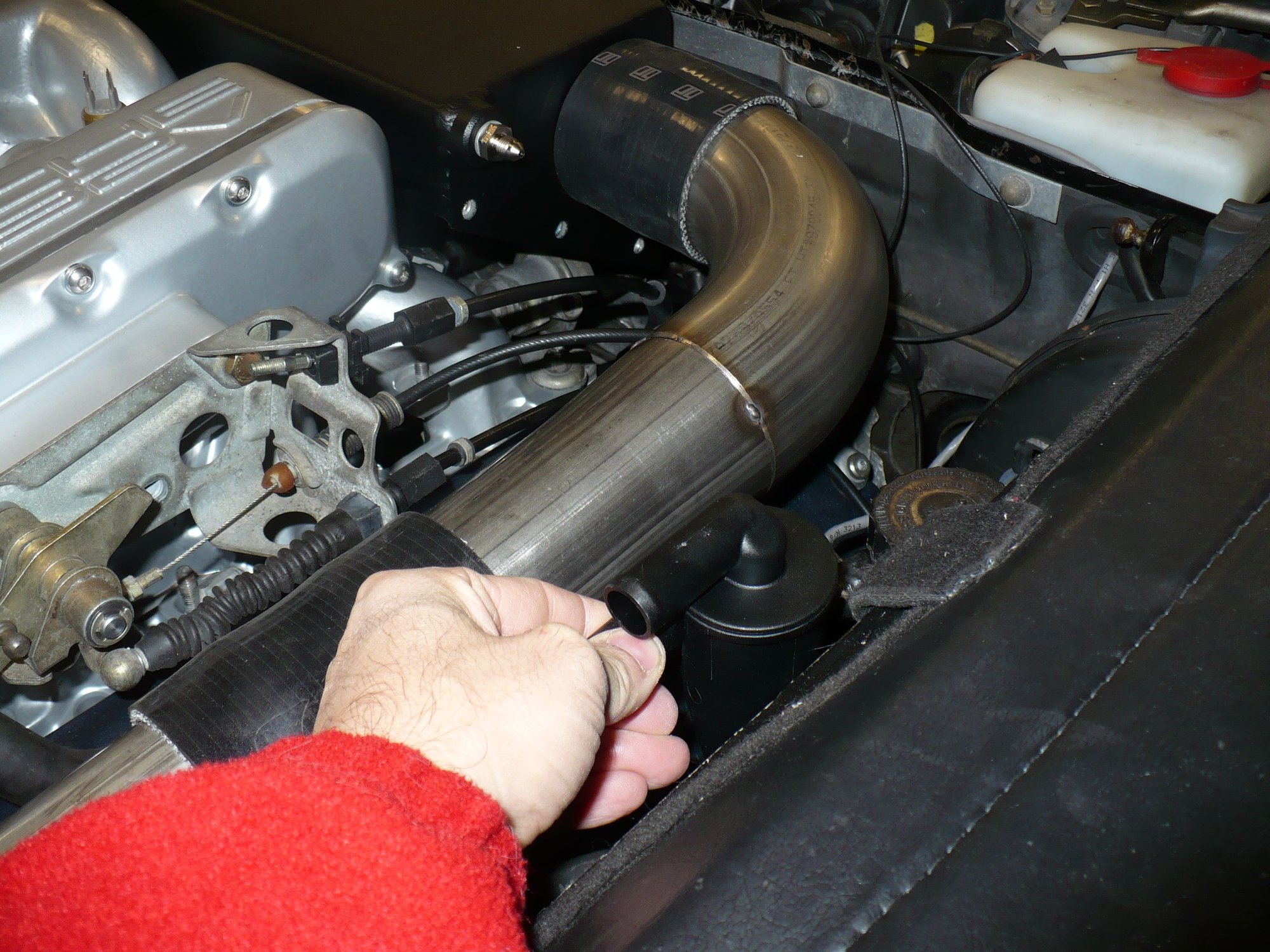
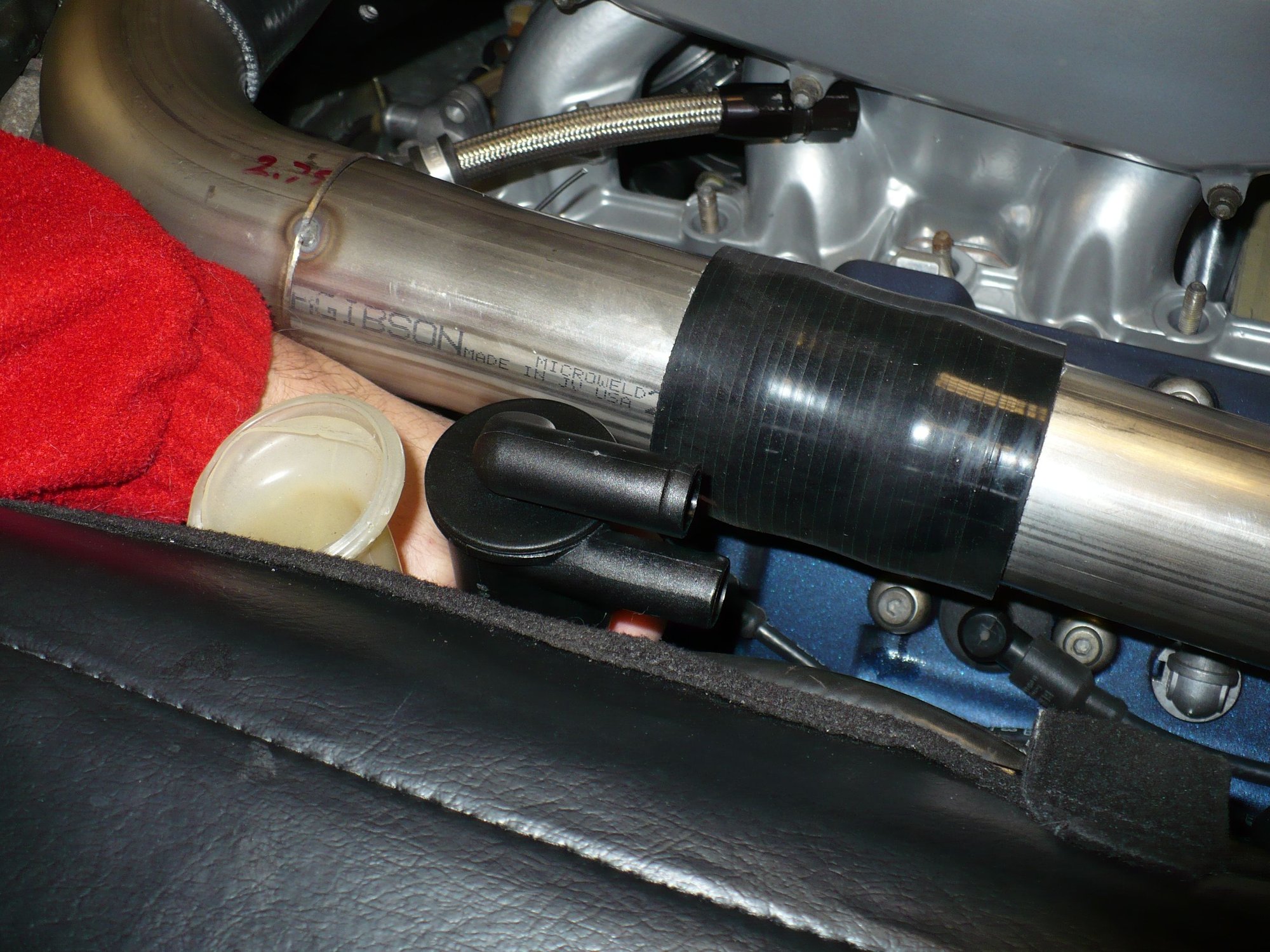
No, they are needed for compliance. The intercooler is firmly attached to the chassis. The compressed air box / plenum is firmly attached to the engine. They have to be firmly attached, because at these cross-sectional areas and boost rpessure the forces are incredibly large. Because the engine rocks on the motor mounts, there has to be enough compliance in the pipes between, and that's why all those silicone couplers are necessary.
intercooler is firmly attached to the chassis. The compressed air box / plenum is firmly attached to the engine.
maybe you can compensate the removal of that connector by putting more flexible connectors at the intercooler and air box? say something like this?? ..
maybe you can compensate the removal of that connector by putting more flexible connectors at the intercooler and air box? say something like this?? ..
The bypass valve pipe to the air box limits the movement further. At this iteration, we're better off safe than sorry, the last thing we need is stuff popping off when the engine rocks.
I think the visual appearance is fine with the coupler there, it's right in the middle of the intake manifold so I think it should look good.
ok just suggesting, sounds good and like they say, you're the boss...great work again, some day I hope to pickup a second 928...and then I will be giving you a call
ok just suggesting, sounds good and like they say, you're the boss...great work again, some day I hope to pickup a second 928...and then I will be giving you a call
I'm happy to talk to you, but really you should google and call/email John Kuhn.
Those couplers are not really ment for the amount of movement the engine produces. There are better shaped ones for that. They have a bulge in the middle that allows a lot more movement. As you probably know, the engine rocks quiet a bit when under load.
Those couplers are not really ment for the amount of movement the engine produces. There are better shaped ones for that. They have a bulge in the middle that allows a lot more movement. As you probably know, the engine rocks quiet a bit when under load.
Are you talking about the black couplers in the pictures? Whether or not they are appropriate here depends entirely on the geometry. With this geometry, fluctuation in the angles that the couplers need to accommodate is minimal. Think it thru.


 11-14-2015, 11:56 PM