When you click on links to various merchants on this site and make a purchase, this can result in this site earning a commission. Affiliate programs and affiliations include, but are not limited to, the eBay Partner Network.
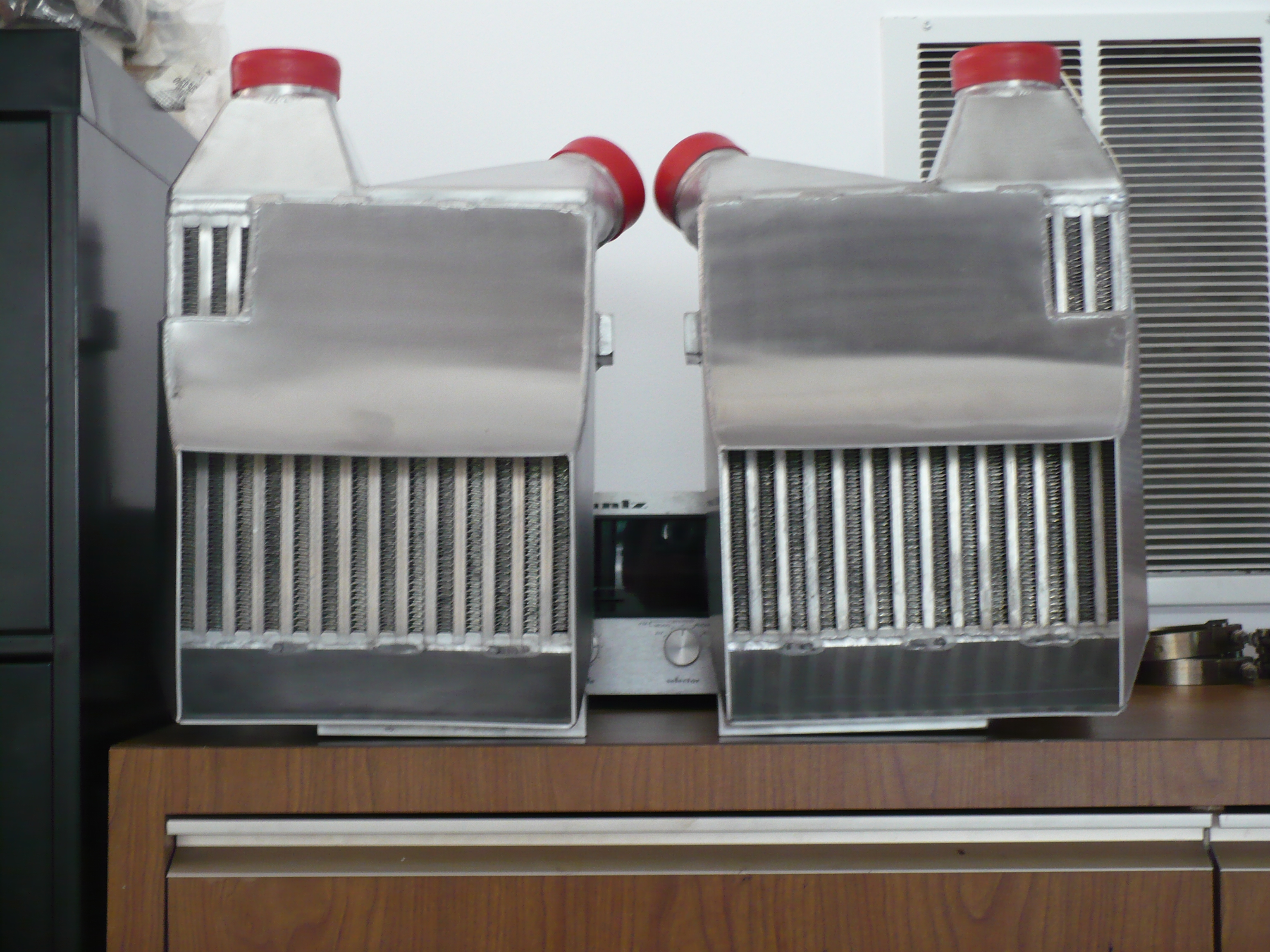
The main determinant of the "hp" capacity of an intercooler is volume. The shape and internal fin design will then determine the tradeoff between cooling efficiency and pressure drop. The math and spacing considerations lead us to an intercooler that is functionally similar to the 944 Turbo and 968 Turbo S intercoolers (but of course two of them for a V8).
How good are you guys at driving? 450 rwhp was more power that I have skill to handle, other than in a straight line for short periods of time. Will 900 rwhp require twice the skill? Is that a linear relationship?
How good are you guys at driving? 450 rwhp was more power that I have skill to handle, other than in a straight line for short periods of time. Will 900 rwhp require twice the skill? Is that a linear relationship?
Can't speak for john but I suck! ;-) but what's the point... This is a science project!
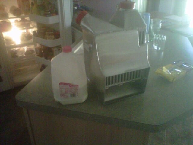
Here's the old ic next to the new one. Big increase in cooling efficiency with some increase in pressure drop as well. Math says the result is more knock limited power for even a 700 hp engine, and there's really no contest at 1000 hp. The difference is mostly the depth, but the new cores are also a little taller:
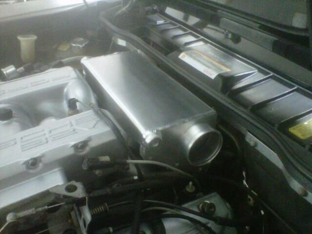
The integrated shroud is going to cut down significant time from the assembly and make fabrication of the ducting much simpler.
We've seen a number of other projects with Y pipes instead of plenum boxes, those y-pipes having dual 90-degree mandrel bend turns merging into a larger pipe that feeds the MAF housing. What's your guess, why do you think this system has a plenum box instead of such a y-pipe?
wow cutitng and welding that stuff up took real talent,,,who did all the fab work ??????? did mr Kuhn make this stuff just wow !!! andy
Some of this stuff John is making in house, some of it's outsourced. However, almost all of it designed in a way that one could subcontract a large series of it without much difficulty to the supply chain that John has put together for his firm. Since everything is designed on a computer with a manufacturing process in mind, one could in theory order say hundred pairs of those intercoolers and a hundred pairs of the exhaust manifolds and get the unit cost down a lot. Not that ou would, but you could! ;-) The two main differences between the existing kit version and this new, larger version are that the new larger version is sized for higher peak horsepower and the larger version has much fewer steps that require purely manual fabrication steps that require tens of hours from a skilled craftsman or artist.
Most of you have no idea (and I certainly didn't) how many design requirements a cast exhaust manifold has, for example. Gas flow requirements, pulse tuning requirements, thermal expansion related durability requirements, requirements for easy machinability of the surfaces, requirements for permanent steel patterns to make the sand casting molds if series goes up, requirements related to how the molten metal actually flows, requirements related to casting precision, etc.
The intercoolers were another project where there were a large number of back and forth exchanges between John and the core supplier on the pressure drop and cooling effectiveness math that had some (integer) constraints related to the existence of cores and manufacturability of the hole assembly. For example, the design is a dual pass intercooler which in this case maximizes the core volume. How much cross-sectional area should one dedicate to the first (down) pass vs the second (up) pass to create an intercooler that is on the efficient frontier of minimum pressure loss for given cooling efficiency? Remember that gas density increases when it cools, so the first (down) pass should be bigger than the second (up) pass. But by how much, taking into account the core temperature in each location in two dimensions? And once that ideal configuration is known, then there's the even more complicated question of which one of the options that meet the manufacturing requirements is the best.
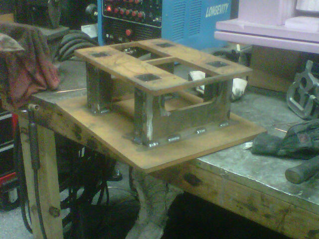
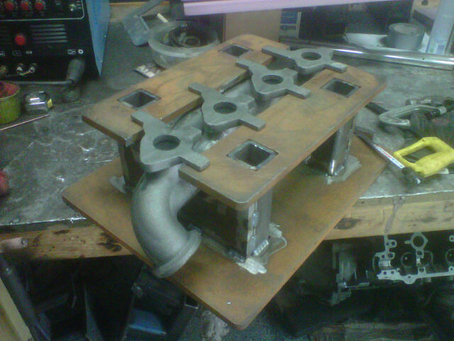
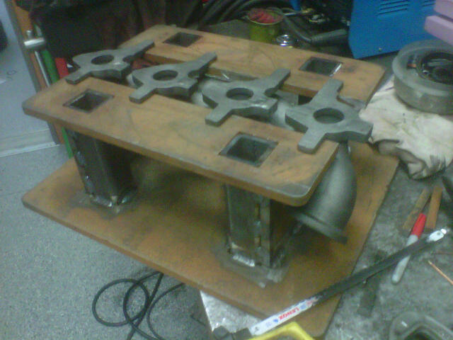
This is my understanding of how the magic will happen. This first fixture indexes the part from the long cast tabs protruding from the main flange. The fixture is used to surface the main flange. This step establishes the first plane in the part interface. A second fixture (not ready yet) will then index the part from this first plane and is used to machine the V-band flange plane. Now, those two planes completely locate the part. As a final step, those two planes are used to index the part and the bolt/stud holes are drilled to the main flange, the tabs cut off, and the primaries port matched. This is a good compromise between precision of locating the raw casting and the complexity of the jigs and machining operations.
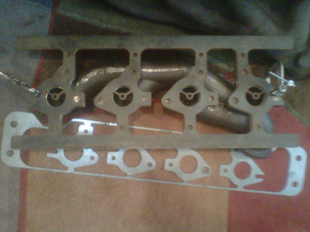
Here's a precision machined plate that is used to check the machine work at different stages. It will also be used to hand blend the primary runner entry, such that there is a smooth transition from the head exhaust pot to the rest of the exhaust primary. Manifold being tested on a manifold in the below photo:
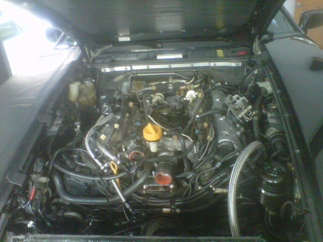
The old, stock engine will be pulled soon. The surgery room in John's shop.
There's some prep to be done on the new, slightly hot rodded and lower compression engine. Exhaust manifolds need to be finished, including tapping the bosses for the slow and fast pressure sensors and fabricating heat shields for the sensors. The exhaust manifolds will need to get TBC on them at some point. We need to go thru the intake and fuel system to understand what we'll use in the new engine from the existing system and what will be new. At this point, my guess is that the old fuel system will stay since it now works and the new, slightly ported intake will go in. The fast pressure sensor bosses need to be welded to the intake manifold, and we're also considering adding a slow pressure sensor to the passenger side plenum cover. A magnesium oil filler neck needs two new breather ports. Etc.
Outside the new engine, there's still a ton of work to do. The new crankcase breather system needs to be assembled. The compressor intake ducting, intercooler ducting, and boost pipes need to be fabricated. Etc.
There's still a huge number of tasks on the list before the new iteration can be tested on the dyno.
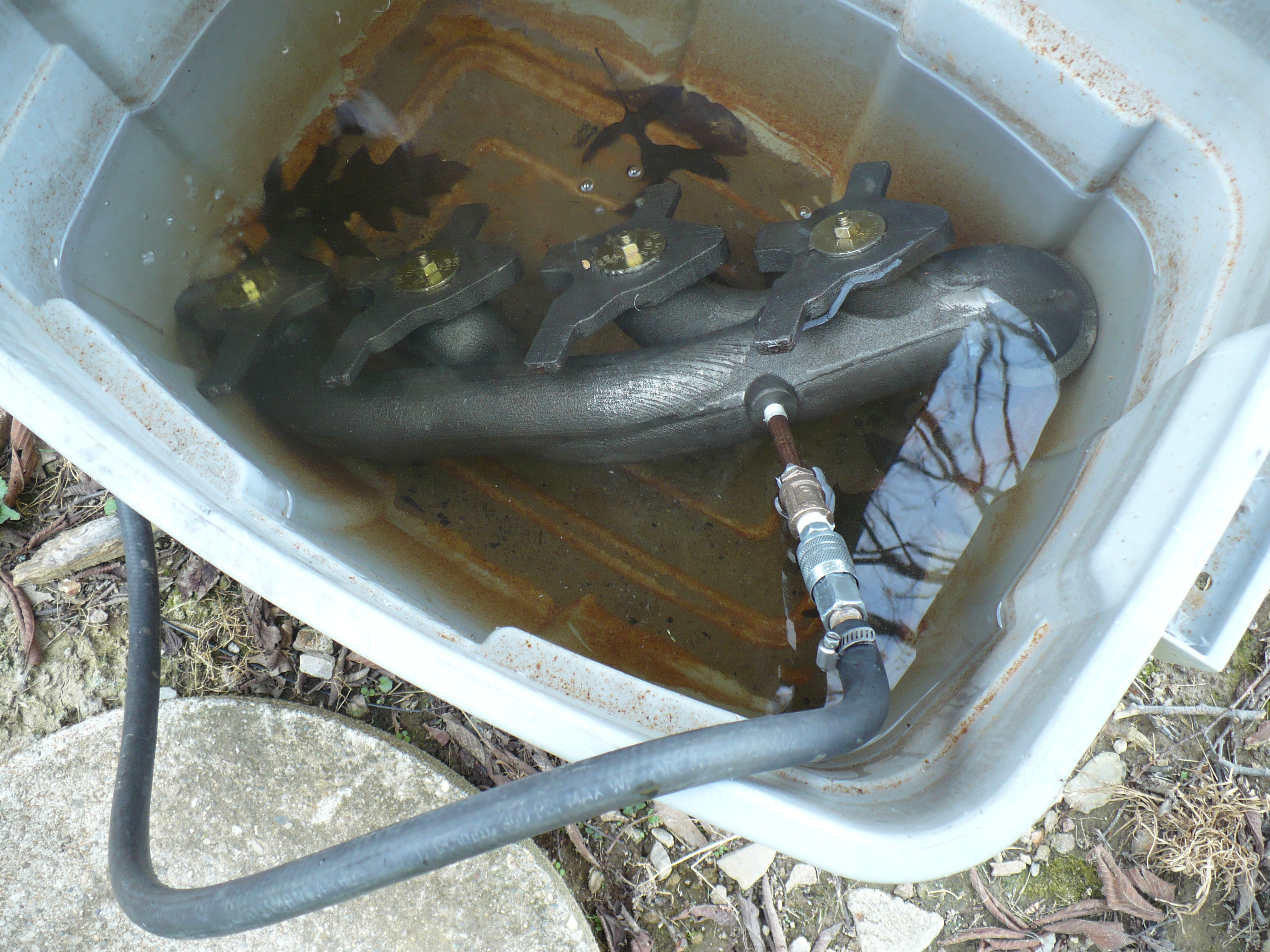
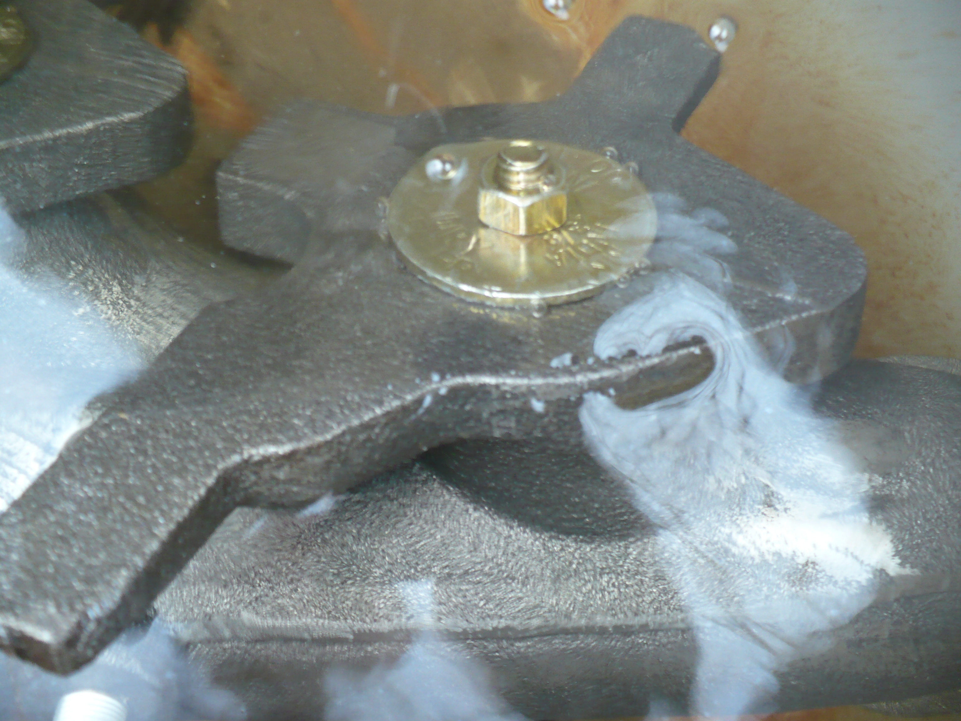
Before spending any money on machining the raw castings, it makes sense to pressure check them. Given that the casting was designed in a fully professional manner and the manufacturing operation was successful, the chance of cracks or other leaks was low. However, they still need to be checked.
There's 100 psi being applied to the manifold that is submerged in super-secret special-sauce fluid in a laboratory environment. The only minor bubbles that are coming out are from the pipe plugs at the ends, and those areas will be surfaced and sealed so those bubbles can be ignored.
After this, the manifolds will be surfaced at the main flange, the v-band clamp connection will be cut, the stud/bolt holes will be drilled, the primary runners will be hand blended to smoothly transition from the exhaust port, pressure ports will be drilled, tapped, and plugged, tabs will be cut off, and the manifolds will be TBC coated after test fitting.
This is a very good way to pressure test anything from cylinder heads to bicycle tubes. Especially cylinder heads before you put down countless of hours of porting work and when finished to find out if you have managed to cut through the port walls or not.
�ke

 07-24-2015, 06:41 PM