When you click on links to various merchants on this site and make a purchase, this can result in this site earning a commission. Affiliate programs and affiliations include, but are not limited to, the eBay Partner Network.
Thinking about dem indakes... After a little bit of research, it seems that the following is the case for normally aspirated race motors:
There are two very different tuning modes, the IVC-IVO tuning and IVO-IVC tuning. They both operate according to the same laws of physics, but just for the sake of intuition they can be approximately described as follows. The IVC-IVO tuning is "like an organ pipe" in an ITB motor and like a Helmholtz resonator in a equally spaced 3 or cylinder plenum. The IVO-IVC tuning is like "intertial ramming". These are just names that are somewhat intuitively descriptive, not an exact description of the physical process.
The same pipe isn't usually the absolute best for both tuning modes, so a compromise is being sought.
Now, to my point: At least in normally aspirated race motors, the designers are giving much less weight to the IVC-IVO "organ pipe" tuning than IVO-IVC "intertial ramming" tuning. This is because IVC-IVO organ pipe tuning is only necessary to get the charge flowing as early as possible (by timing a high pressure wave in the intake port at the same time as IVO). The race motor designers can use the exhaust waves to get a low-pressure wave into the combustion chamber and there will be sufficient pressure differential even if the IVC-IVO "organ pipe" tuning is not "spot on". Because both valves are open during the overlap, there are diminishing returns from a bigger pressure differential -- beyond certain pressure differential between the intake valve and exhaust valve the charge is just going to start going out the tailpipe. So with a good race engine exhaust, the IVC-IVO tuning becomes less important.
Very much simplifying, the race motor design process seems to be the following:
(1) Size the intake runner for the IVO-IVC inertial ramming tuning at the desired rpm.
(2) Let the IVC-IVO organ pipe tuning be whatever it ends up being.
(3) Design the exhaust header such that the pressure differential between the intake port and exhaust port at the IVO is above some minimum level across the operating rpm range and slightly increasing in the rpm. That is, tune the "header" such that it resonates when the intake IVC-IVO tune is off and doesn't when it's on.
Contrast this with a street car motor. In a street car motor, the exhaust is restricted in many different ways. Overall, the average exhaust pressure is higher, the dreaded back pressure... The exhaust tuning isn't completely free because of chassis restrictions. Excessive overlap makes the engine hard to drive on the street. Etc.
Now, with a street car, it's no longer the case that the designer can ignore the IVC-IVO organ pipe tuning. Instead, the designer has to compromise a little bit on the IVO-IVC intertial ramming tuning to tune the IVC-IVO organ pipe tuning better with the operating rpms. This is because the overlap isn't long enough and the exhaust isn't powerful enough to pull the charge to the exhaust pipe at all IVO pressure conditions.
I think this is one of the reasons why street cars have all sorts of complex Helmholtz resonator intakes with resonance flappies etc. while the race cars don't. This may also be the case why engines with race-car like exhaust seem to make a lot of power even with what appears to be excessively short ITB intakes. The short stack may work great for IVO-IVC intertial ramming tuning but tune at best a high order resonance for the IVC-IVO organ pipe tuning, but the latter doesn't matter because the exhaust is going to pull the charge in at IVO no matter what.
(Another reason is of course that the race cars don't need as wide of a power band, that is obviously also a part of the explanation.)
So, should the turbo intake look like a race car intake or a street car intake?
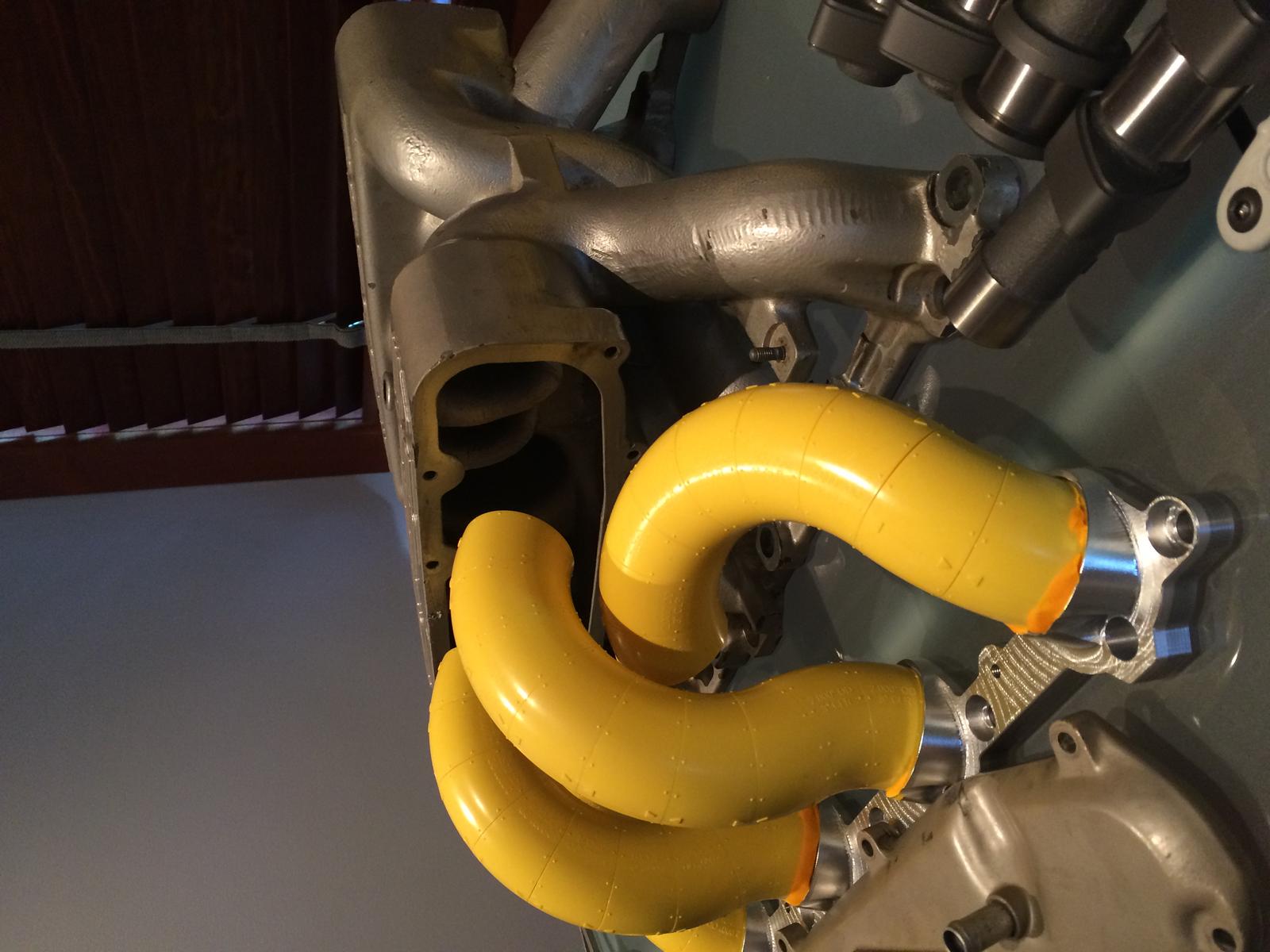
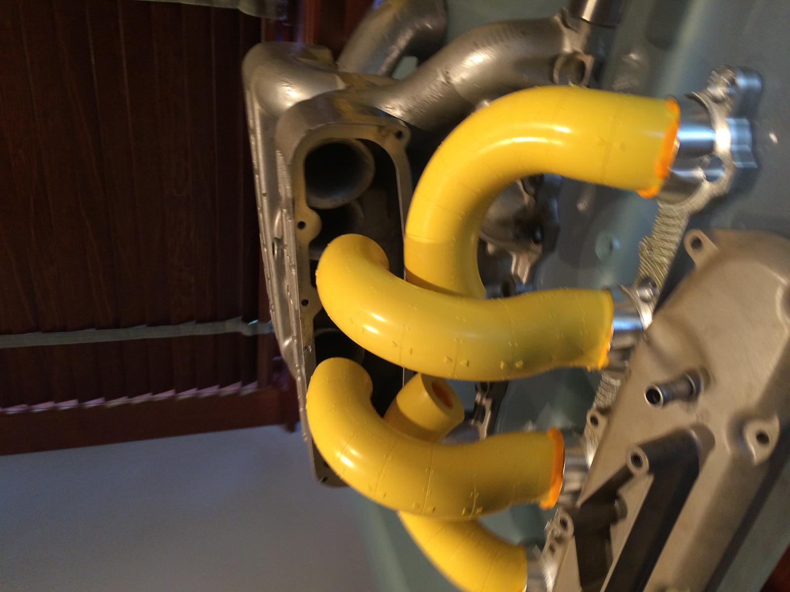
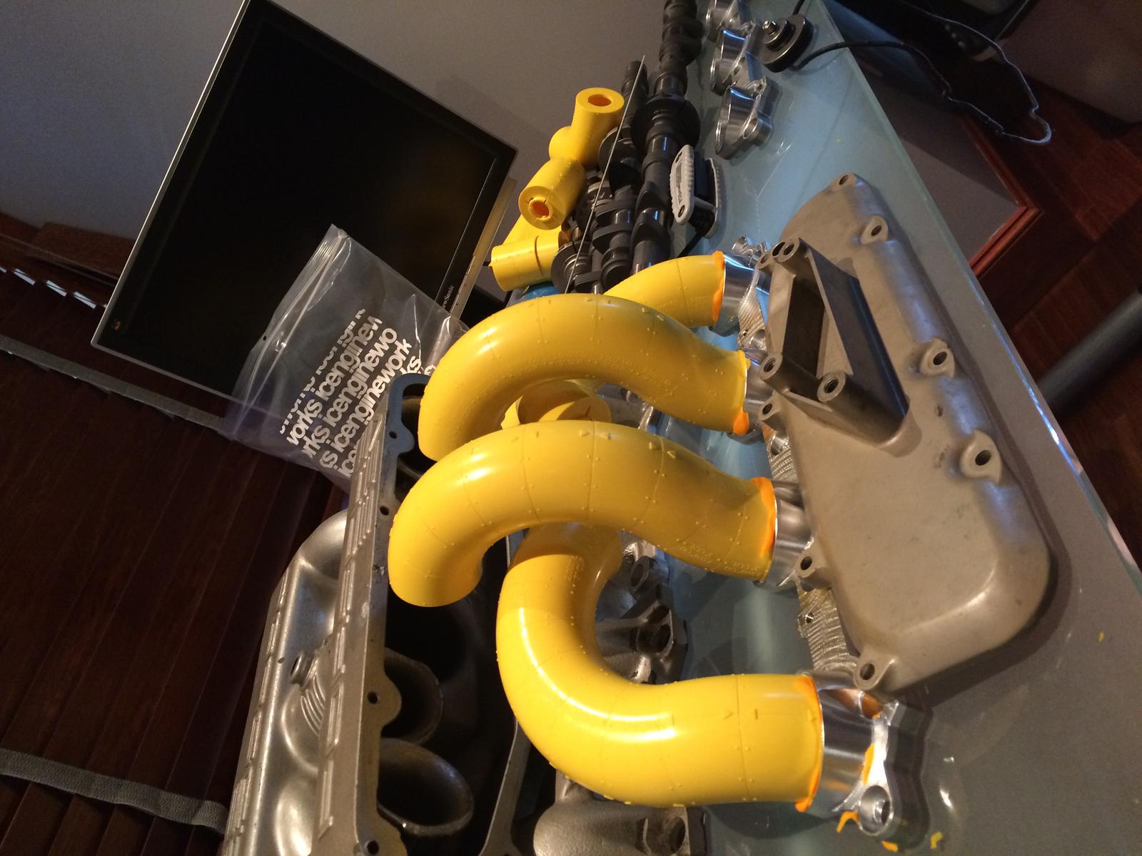
I am tempted to try some 8" runners in a single plenum intake. Temptresses they are, those flanges:
I'm afraid I have nothing more than 'gut feeling' to add to this, but, I feel shorter, slightly tapered is the way to go, if those are 8" I'm thinking 4".
Like I said nothing more than gut feeling I'm sure you will come up with something more scientific....
I'm afraid I have nothing more than 'gut feeling' to add to this, but, I feel shorter, slightly tapered is the way to go, if those are 8" I'm thinking 4". Like I said nothing more than gut feeling I'm sure you will come up with something more scientific....
That's one viewpoint. As a counterpoint, [I know some ladies who are] not getting a gut feeling from anything shorter than 8".
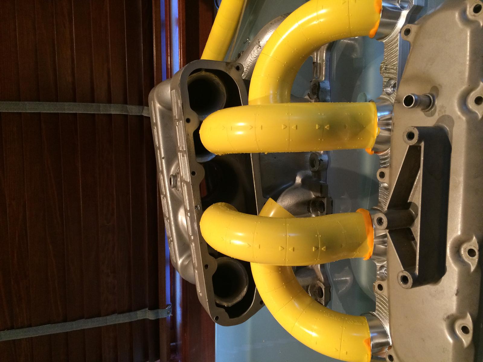
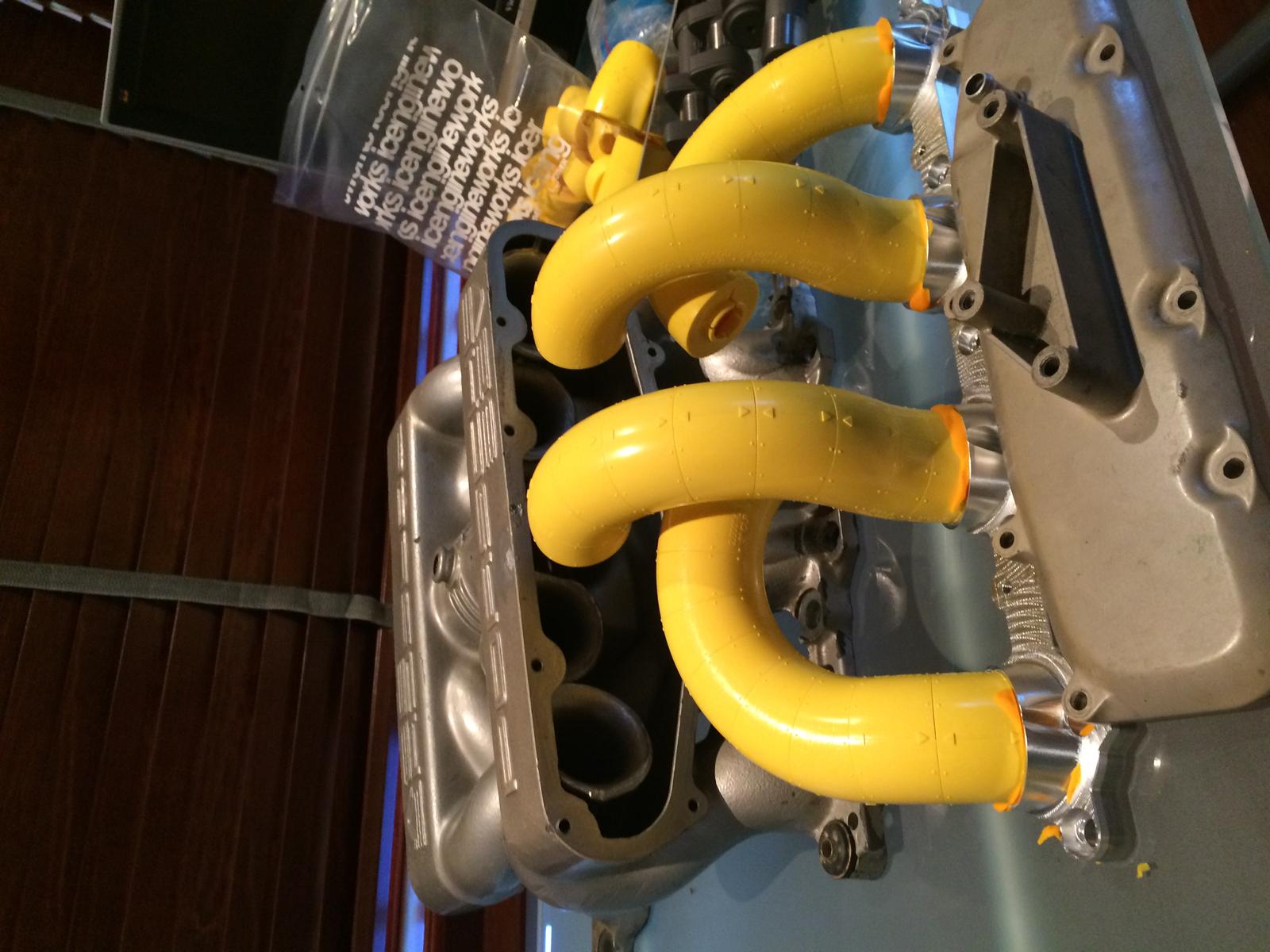
Here are some 7" plus flange runners that would package with reasonable ease and make the total intake tract length a hair shorter than 12":
Are you considering that the increase in intake charge density will decrease the resonant runner lengths? This might bring you to a slighly shorter tube.
Tuomo, Are you considering that the increase in intake charge density will decrease the resonant runner lengths? This might bring you to a slighly shorter tube.
I am not, because it's not true. Well, it's technically true but the impact of density is exactly offset by the impact of pressure in ideal gas laws. Of the pressure, density, and temperature, only temperature matters. Specifically, the speed of sound is about proportional to the square root of absolute temperature. That makes a huge difference on the exhaust side, but doesn't matter that much on the intake side given that I have the big intercoolers.
The internet is so full of intake runner formulas that it's about to burst from its seams! There seems to be two kinds of formulas out there, simple empirical formulas and complicated theoretical formulas.
The simple empirical formulas that have no theory behind them but have been calibrated based on dyno experiments seem somewhat predictive.
I don't believe in the more complex formulas. The reason why I don't believe in the more complex formulas is that they are either motivated by the IVC-IVO harmonic wave theory or IVO-IVC finite wave theory but not both. Furthermore, depending on cam overlap and exhaust configuration, the relative importance of IVC-IVO tuning and IVO-IVC tuning can be dramatically different.
Specifically, I don't think that the harmonic waves contemplated by many of these theoretical formulas have much to do with the intake tuning in the EVC-IVC period. It's finite waves (defined as waves when the gas flows relatively fast compared to the speed of sound) and when you see actual or simulated pressure traces, they don't look at all like organ pipe waves (harmonic waves, defined as waves when the gas doesn't flow fast relative to the speed of sound). Instead, they look like a single tsunami flooding the cylinder without sine wave in sight.
The only time when the harmonic wave computations make any sense are during the IVC-IVO period and specifically the objective should be to produce a pressure condition that is meaningfully higher (but not too much higher) than the exhaust port pressure at the IVO. This pressure differential at overlap has to get the gas exchange going in the right direction as early as possible, and once it's going one can toss the harmonic wave theory in the trash can and it's all finite waves since then. The reason why I say the pressure differential between intake port and exhaust port shouldn't be too high is that if it's too high it'll just blow the fresh charge out the tail pipe during the overlap.
This compromising between IVC-IVO tuning and IVO-IVC tuning explains why tuning the third harmonic based on the harmonic wave formulas makes the most peak power for a normally aspirated engine with redlines such as 7500 rpm. Just thinking in terms of the harmonic wave formulas, lower order resonances create the strongest pulses and thus one would erroneously conclude that one should always tune the pipes for the lowest order that one can fit. The harmonic wave formulas predict that most power is made with really, really long intake pipes but in reality we don't observe that in actual running engines. It turns out that the harmonic wave formulas give wrong predictions because they ignore the most important part of the intake tuning which is the IVO-IVC tuning. For IVO-IVC, the 1st and 2nd harmonics from the formulas give too long pipes and loose peak power. (The 2nd harmonic can give nice street car motor, of course, if the exhaust is well tuned to between the 2nd and 3rd harmonic. But it doesn't usually give the most power.)
Why am I going on and on about this in logical circles? I am trying to understand why many the turbo cars now have very short runners. Without a doubt, many times that's because the short runner intake is the easiest thing for a hobbyist to fabricate. But now even the big budget car factories are making turbo intake manifolds with relatively short intake runners. I am trying to understand this.
One way in which I've been able to rationalize it is the following. The turbo exhaust manifolds have very short runners nowadays, since that gives many benefits. I am thinking that long runners are going to be "off tune" for the IVC-IVO period at some rpms, such that there's a low pressure wave at the intake valve at IVO at that rpm. With a normally aspirated engine you deal with this by tuning the exhaust to also have a low pressure wave at the exhaust valve at that rpm, maintaining the favorable pressure differential between intake and exhaust ports at IVO. However, with the turbo engine other considerations are more important for exhaust side and the short pipes can't be used to specifically tune to the rpms where the IVC-IVO tuning is off in the intake side. Therefore, the turbo intake design is mostly just about avoiding creating low-pressure waves at the intake valve at IVO across all rpms.
Still, that all said, I am greedy and I'd like the 3rd harmonic to help me out when the engine otherwise runs out of breath at the top end, with turbines chocking, cams falling on their faces, back pressure building up, etc.
After a couple of false starts, John will get the two v-band clamp flange cutter tools next week. Expect the first set of exhaust manifolds to be ready (short of TBC coating) week from now.
Is there something one should definitely do while you're at it when the engine is off the car before you put the engine back into the car?
I think the next iteration will run the cams pretty far advanced. All the previous experiments were run with stock S4 cam timing which is from memory 6.5 (?) degrees retarded. My logic says that with a turbo car, I want to advance the cams significantly from that setting. That is, the motor needs to perform well as a normally aspirated engine up to about 3500 rpm after which the compressor unleash their fury. Advancing the cams will by my logic help for two reasons. First, the intake will close earlier, which will help trapping more air at low rpms. This is the usual normally aspirated logic. Second, and specifically for turbos, advancing the cams will also open the exhaust valve earlier. Earlier exhaust valve opening will lower the efficiency by "wasting" heat and pressure out of the exhaust port instead of having it push down the piston. But of course, this being a turbo car, that will bring down the boost threshold rpm because there's more energy to drive the compressor at low rpms.
Is there something one should definitely do while you're at it when the engine is off the car before you put the engine back into the car?
Upper A-arms are a lot of "fun" to R&R with the engine installed. They will be nigh-impossible with all your turbo bits. Mark sells nicely-rebuilt units on a core exchange basis.
I second the nomination of the clutch master and blue hose for the same reasons as above.
The single AC line with a hose sub-component in the engine bay cannot be replaced with the Porsche part (without some serious bending) with the engine installed. However, the hose part can be replaced if you have the proper compact hydraulic crimper. This, of course, if AC is a priority.
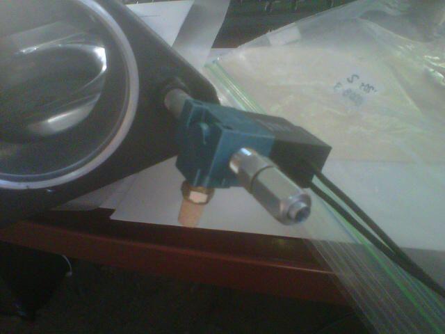
That's a turbosmart solenoid that controls the boost. The solenoid will tuck in under the boost pipe and will not be visible, yet it'll be very easily accessible. We'll be running a pressure offensive control in which both sides of the diaphragm are controlled electronically. There are two benefits: The wastegate will not get pushed open at all before the controller so desires and we can run a weak spring in the wastegate which will allow for low boost set points in some profiles.
Engine mounts, clutch blue hose (from reservoir to master cylinder) and clutch master cylinder would be my top picks for doing with the engine out.
Originally Posted by BC
Ac lines. Cleaning. Lots and lots of cleaning. Better firewall insulation.
Originally Posted by worf928
Upper A-arms are a lot of "fun" to R&R with the engine installed. They will be nigh-impossible with all your turbo bits. Mark sells nicely-rebuilt units on a core exchange basis.
I second the nomination of the clutch master and blue hose for the same reasons as above.
The single AC line with a hose sub-component in the engine bay cannot be replaced with the Porsche part (without some serious bending) with the engine installed. However, the hose part can be replaced if you have the proper compact hydraulic crimper. This, of course, if AC is a priority.
AC is a priority. This project would have been done years ago if it would be acceptable for the AC to not work!
Originally Posted by Tony
cool yellow legos!!
Pricey and fragile, but it's nigh impossible to design manifolds in space constrained settings from standard bent tubes without something like this.
Sorry to disturb your intensive intake discussion Tuomo, but check the document where NASA guys invented tube to reduce pressure loss of 90 degree bend.
You'll find it using search words: "Flow Restrictions in Intake Designs - T Moss". I'm having kind of impression that you may need something similar in your project.
This was actually in my mind while talking about cobra head shaped pipe and found it again one day.
If you go back in the thread, we optimized the turn into the box and the pressure loss was so minimal with the round tube was sufficient.
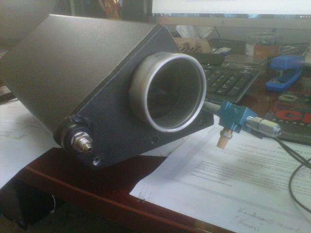
The box itself has a diffuser in it that slows down the air and a guiding wane that turns the slowed down air into the direction of the MAF with what believe is very low turbulence. The MAF then sucks from a bellmouth that can draw from 360 degrees around it. The setup is pretty similar to the bottom of the stock air box, except there's that guiding wane in the boost box (and not filter).
This is precisely because a simple Y from two 90 bends welded together wouldn't have worked as well given that we use the stock MAF in the stock location. It's too close for a fast bend, you have to have a bellmouth in a box feeding the the MAF.
Originally Posted by simos
Sorry to disturb your intensive intake discussion Tuomo, but check the document where NASA guys invented tube to reduce pressure loss of 90 degree bend.
You'll find it using search words: "Flow Restrictions in Intake Designs - T Moss". I'm having kind of impression that you may need something similar in your project.
This was actually in my mind while talking about cobra head shaped pipe and found it again one day.

 10-02-2015, 10:10 PM