When you click on links to various merchants on this site and make a purchase, this can result in this site earning a commission. Affiliate programs and affiliations include, but are not limited to, the eBay Partner Network.
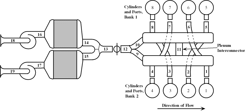
Intake side of a simulation model is close to being ready and exhaust is under the way. Getting valuable help from the person who wrote the simulation package:
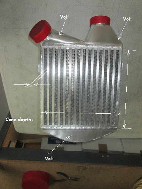
Everything gets mapped into the software in fairly detailed ways. For example, the intercooler modeling requires the following data:
The passage length of the intercooler core is approximately 10�, or 20� since it�s a dual pass configuration.
The passages have an internal cross-section of 0.24� x 5.9�. There are 8 passages down to the bottom end tank and 7 passages up. That�s about 11.3 sqin of flow area on the way down and about 9.9 sqin of flow area on the way down. The logic of dividing it that way is that the first pass already cools the charge and makes it denser, so less flow area is needed.
The bottom end tank is 6� deep and 10� wide to match the core. The curve has a radius of 5� and the tank has horizontal depth of 2� at the center. Segment area is about 11.2 sqin and the volume thus about 67 ci.
My guesses for the inlet end tank volume is 25 ci and for the exit end tank volume is 35 ci. Those are ballpark guesses, I just eyeballed them and didn�t get them from John Kuhn�s CAD model. Since those are volume parameters, those can easily be adjusted to more precise measurements down the road.
Twin Turbo 928 fixed and back out there terrorizing the streets!
Originally Posted by ptuomov
Intake side of a simulation model is close to being ready and exhaust is under the way. Getting valuable help from the person who wrote the simulation package:
Everything gets mapped into the software in fairly detailed ways. For example, the intercooler modeling requires the following data:
Pretty neat to do such a simulation. Is it taking the length, number of turns with angles and radii from filter to valve on a stock manifold? Or are you doing a custom manifold for the low compression engine?
Pretty neat to do such a simulation. Is it taking the length, number of turns with angles and radii from filter to valve on a stock manifold? Or are you doing a custom manifold for the low compression engine?
This engine will have a stock intake manifold with some small but IMO thoughtful modifications. The simulation is 1D so the lengths are always part of the equation, while number of turns and their radii will have to be entered as loss coefficients.
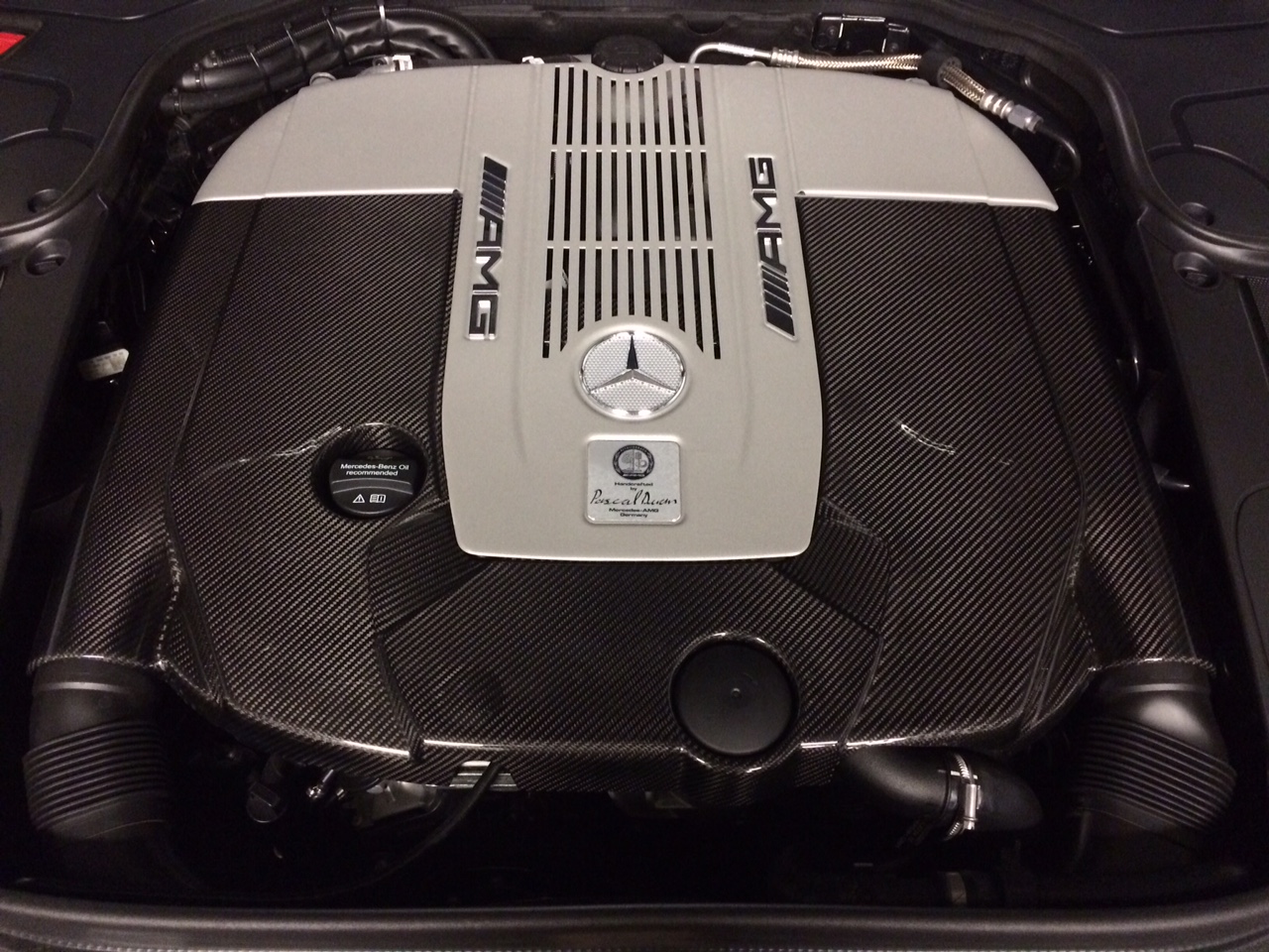
On other news, the S65C came and is awesome. I traded in the Carrera GTS Cabrio and gained six cylinders and two turbos! ;-)
Twin Turbo 928 fixed and back out there terrorizing the streets!
Originally Posted by ptuomov
This engine will have a stock intake manifold with some small but IMO thoughtful modifications. The simulation is 1D so the lengths are always part of the equation, while number of turns and their radii will have to be entered as loss coefficients.
On other news, the S65C came and is awesome. I traded in the Carrera GTS Cabrio and gained six cylinders and two turbos! ;-)
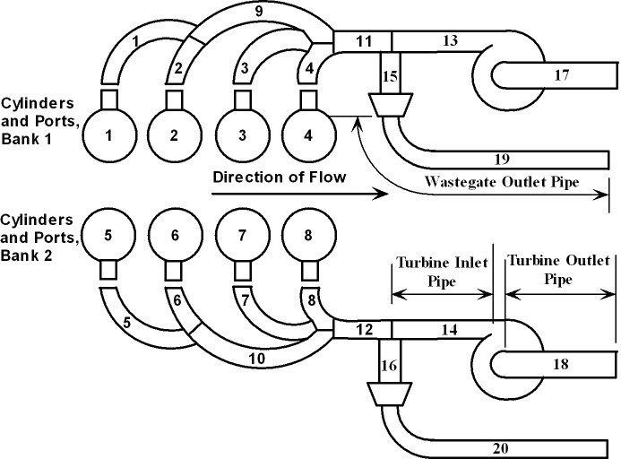
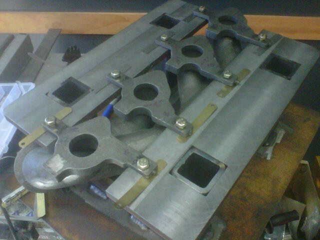
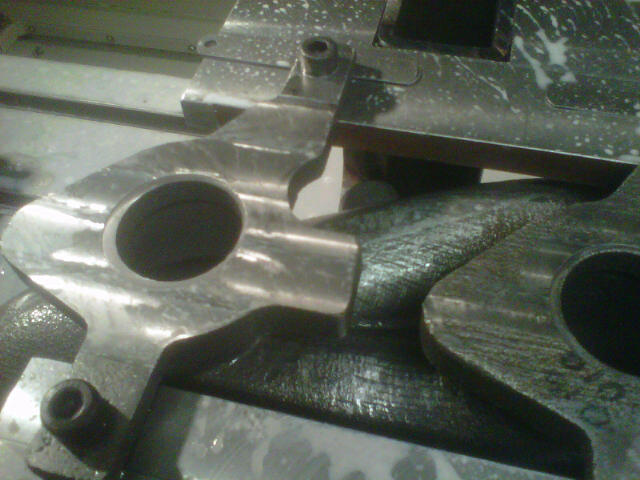
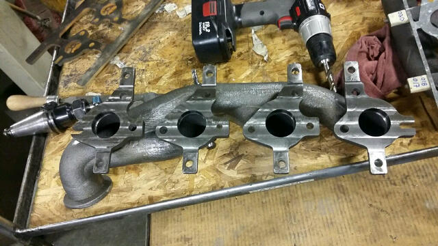
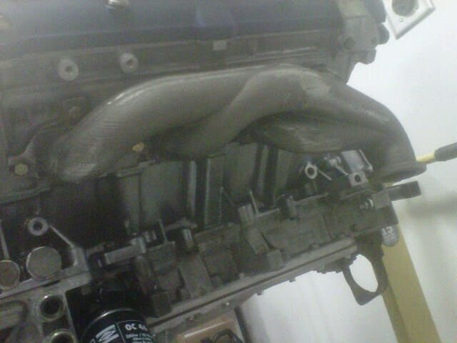
John's putting in some quality time with the exhaust manifolds
Machining those exhaust manifolds is in principle a simple process, but working out every step the first time still takes time. The subsequent manifolds will then be post processes using the same recipe.
The exhaust manifold needs to placed level on the fixture. The most practical way to do that, albeit a bit time consuming, is to shim it such that the raw casting as straight as possible and isn't bending.
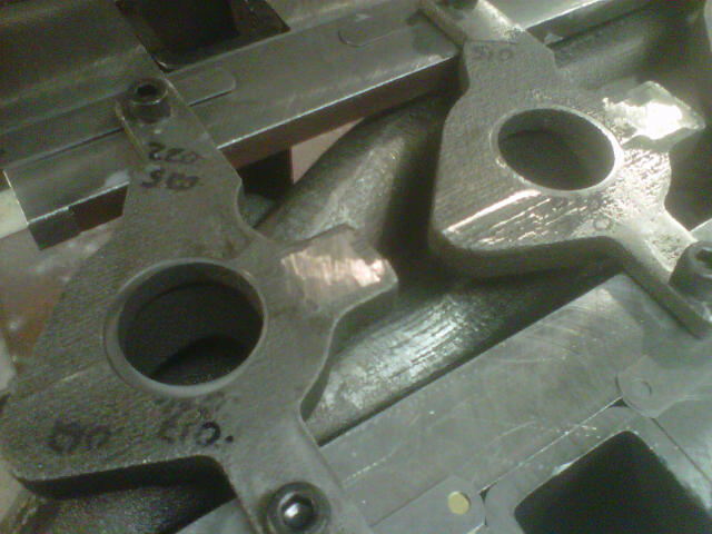
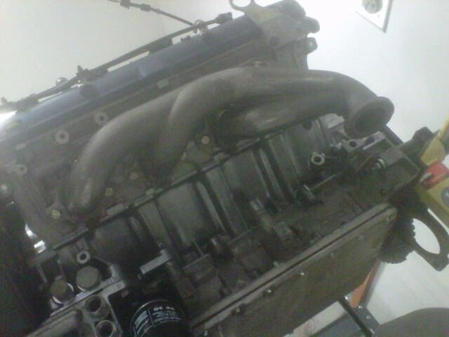
Testing the shims in the privacy of one's own workshop:
The backs of the casting tabs are still as cast, so they aren't not exactly the same between different pieces. The raw casting needs to be shimmed on the fixture such that both the turbine side is in the right location and the main flange is level and not rocking or bending. The first thought might be to surface the backs of the tabs first, but after thinking about it for a second one realizes that the raw casting would have to be held level for that first operation to take place, making it a fools errand...
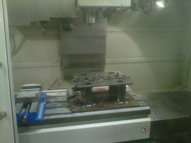
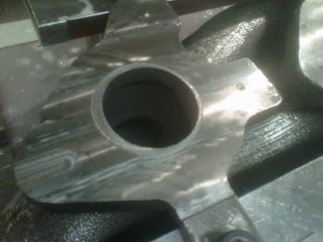
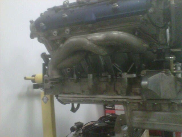
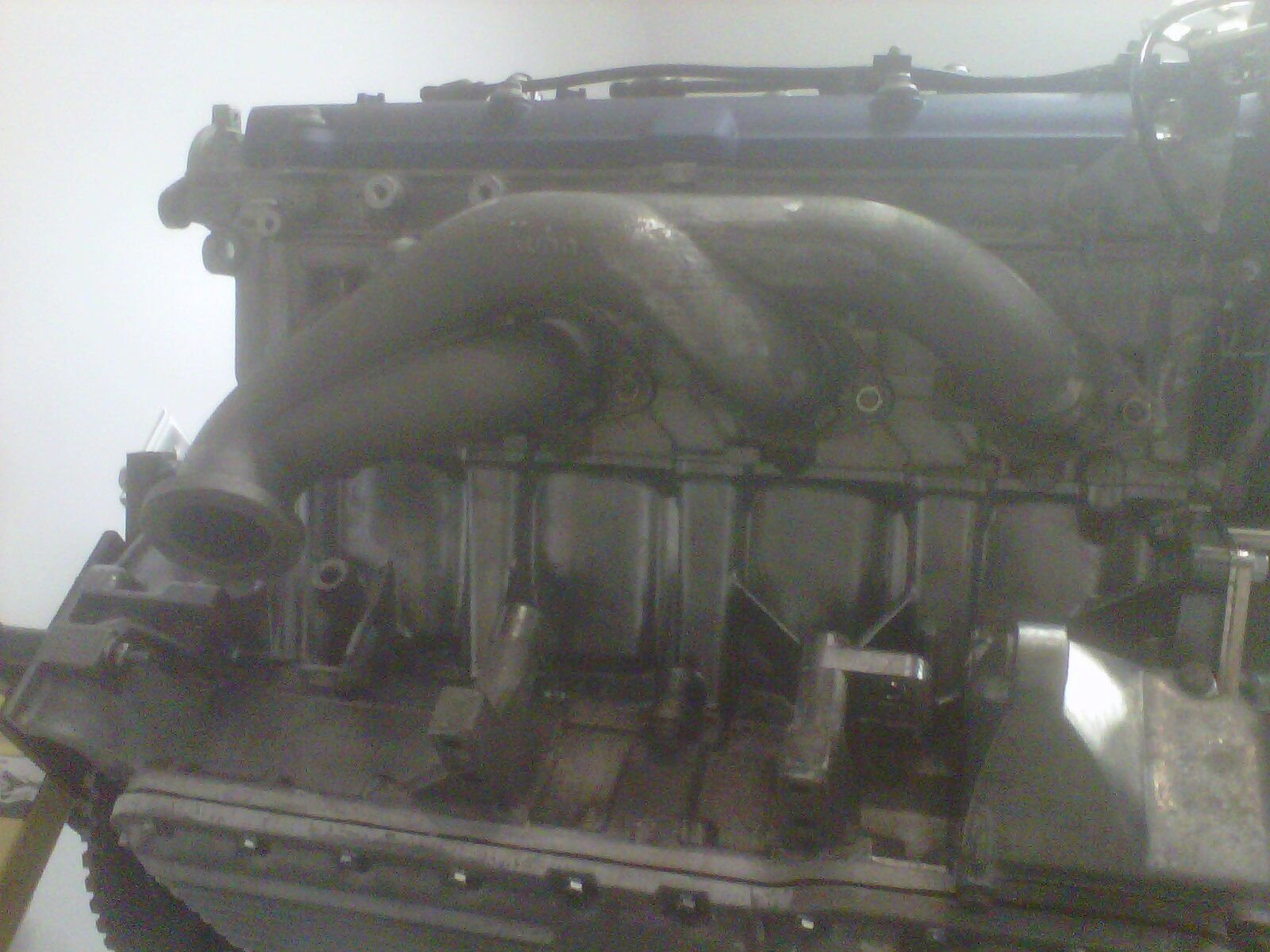
This is at the shop, the real deal:
"It'll be quick and it won't hurt. You won't feel a thing."
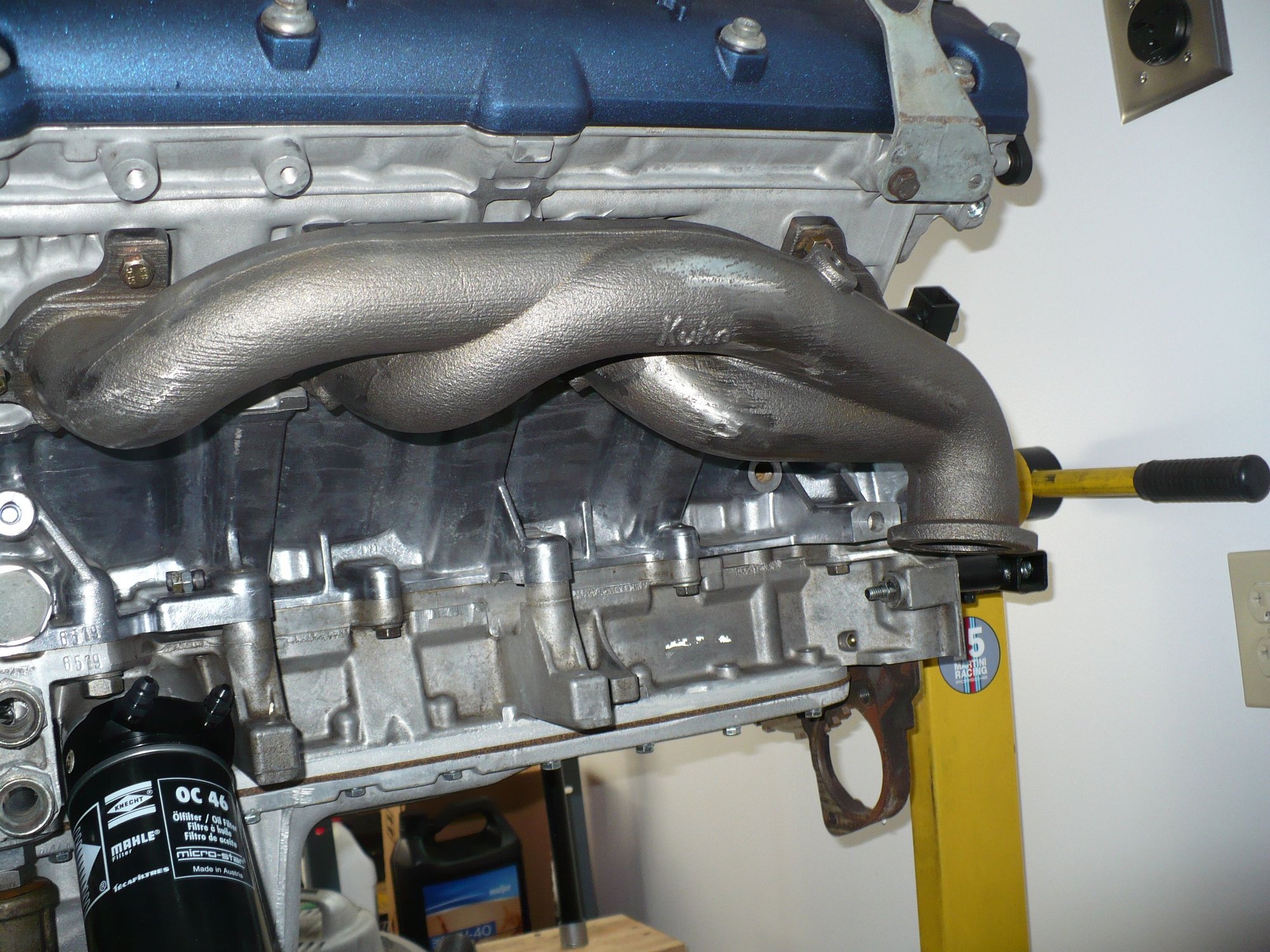
This first manifold will come on and off the machine a number of times for test fitting, checking, etc. John's being very cautious with this first set. The subsequent sets can be all machined in two steps on the same machine, so it should be reasonably efficient.
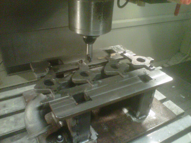
He will do all the functions on one machine. The ports will be 41mm and will be matched to the head. Those are profiled and then the holes will be hit and checked before it is finally faced and then finally drilled. We are being very cautions with this first set.
Right now we are facing down like 1mm and then he will run a spot drill at all the locations and we will check with the template...then final face and re-drill all the way through. The ports will be perfecty matched and will be 41mm
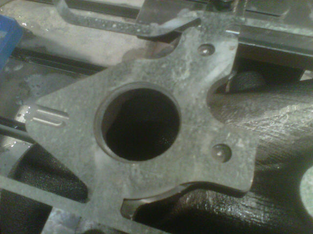
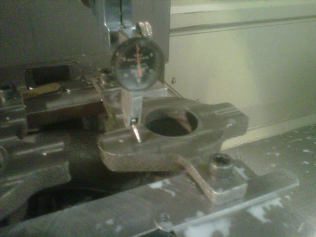
Checking to template.
Finished flange:
The main flange is finished and now John has CNC programs so the next set can just be shimmed on and everything will run pretty much automatically. The tabs will be cut off by hand and there's minimal hand blending at the runners, but that's all.
The v-band clamp interface will be done next week, following a similar process. No shimming needed, though, now that we have a precision surface and bolt holes to index the casting by.
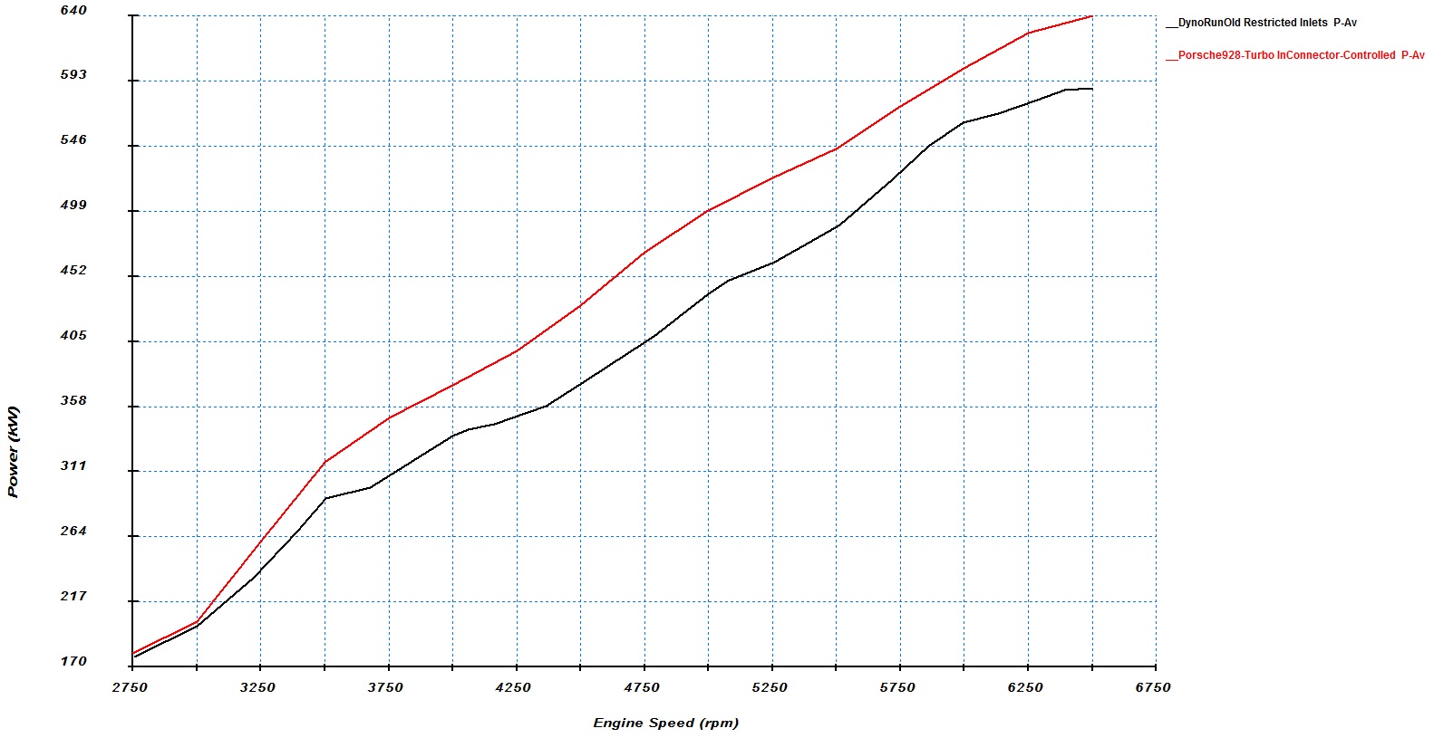
Here's a simulation that seeks to model the previous version of the turbo system.
The is a graph of the actual dyno run (black) described in one of our many, many .xls workbooks compared to the simulation run (red) from Vannik's software. The dyno run is grossed up by the assumed driveline losses.
The compressor inlet pipes in the previous system were designed for about 600 hp so at these higher power levels they were a restriction. The restrictive inlet pipes are modeled reasonably accurately in this simulation run. The simulation software now has the intake resonance flappy valve programmed as well.
There's still about 50 kW power gap between the model and reality, which is likely caused by assumed ignition timing being too advanced compared to the dyno run and the stock S4 intake manifold model being too optimistic in terms of flow. The simulation uses the estimated best torque spark timing, which at highest mass fill rates is about 26 degrees. The actual dyno run was done with 93 pump gas and the knock-limited spark advance was about 14 degrees. With high-octane race gas, we could have run mid twenties spark advance and make more power with the stock engine. The normally aspirated version of the simulation gives a little higher than predicted power, too, because of the intake manifold modeling issues.
We'll keep improving the model to use the actual ignition timing and add some flow losses to the intake manifold. Once the model gets the previous version right, we can start experimenting to check whether the new system really has 1k rwhp potential.
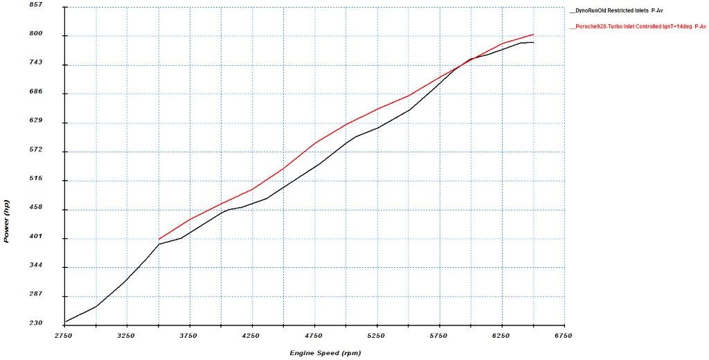
Here's the simulation vs. dyno using the ignition advance that we actually used on the dyno:
Crank hp, the chassis dyno grossed up to be in the same units as the simulation.
It's starting to match pretty closely.
Now we know the simulated maximum unburned end gas temperatures that correspond to real-life knock conditions. This will be useful in further experimentation.
Where do you talk about the engine you built for this next stage?
More on that engine and who built it on a later date. Right now, the focus is on the stuff outside the engine that's designed to run with any engine, including the stock engine.
The above simulation is for running the stock engine with the old pipes and as-it-was-run-on-dyno ignition timing, by the way.
Will you be coating the Manifolds? The real way - Swain. The older pics you have suggest that was done previously.
Yes. The manifolds themselves would last just fine without coating, but mine will be coated regardless of that because I want to keep the underhood temperatures as low as possible. There's also some heat shielding that is part of the system, which will also likely be coated from one side. Belts and suspenders, belts and suspenders...

 08-29-2015, 12:16 AM