When you click on links to various merchants on this site and make a purchase, this can result in this site earning a commission. Affiliate programs and affiliations include, but are not limited to, the eBay Partner Network.
P, since not much can be done to make the stock intake flow higher, have you considered instead to make it flow more uniformly?
Concept-wise, find out the CFM of the worst flowing runners are. An easy guess with a manifold right in front of me would be 5 and 8.
Likewise, find the best flowing runners, 2 and 6, and restrict them down to flow like 5 and 8. And continue the same with the rest.
Theoretically, since now all runners flow the same, you don't have to tune-down to the worst cylinder(s) anymore, and all cylinders will have roughly the same air/fuel ratio.
Thinking about that peach-can video you posted, it showed that adding just a small bell-mouth to the straight pipe improved flow.
So my idea is to completely remove the bell-mouths on both 2 and 6 which will reduce their flow and will put them closer to choked-down 5 and 8.
Removing the bells versus installing a restrictor, you don't have to worry about the restrictors coming loose.
As I'm typing this, I realize this will work with a NA engine too.
P, since not much can be done to make the stock intake flow higher, have you considered instead to make it flow more uniformly? Concept-wise, find out the CFM of the worst flowing runners are. An easy guess with a manifold right in front of me would be 5 and 8. Likewise, find the best flowing runners, 2 and 6, and restrict them down to flow like 5 and 8. And continue the same with the rest. Theoretically, since now all runners flow the same, you don't have to tune-down to the worst cylinder(s) anymore, and all cylinders will have roughly the same air/fuel ratio. Thinking about that peach-can video you posted, it showed that adding just a small bell-mouth to the straight pipe improved flow. So my idea is to completely remove the bell-mouths on both 2 and 6 which will reduce their flow and will put them closer to choked-down 5 and 8. Removing the bells versus installing a restrictor, you don't have to worry about the restrictors coming loose. As I'm typing this, I realize this will work with a NA engine too.
This engine has a mildly ported intake manifold that improves the balance between cylinders. It's not the "ultimate" porting job in terms of equalizing the steady state "flow bench" flow across runners, but it's pretty good. The "ultimate" runner balancing job would require adding some material to the manifold on the outside for the runner 5. Welding in turn may cause some distortions that may lead one to have to skim all the surfaces and attempt to rebore the flappy valve bore. If I ever end up in the direction of having to add material to the outside surfaces of the stock intake casting, I will first try epoxy-aluminum mixture because it's so much easier on the part. In any case, I think the intake manifold is in a decent place already in terms of steady state flow-bench flow.
The next issue is that we have unequal runner lenghts, we have some 20cm and some 30cm runners, which then make for a total intake tract lengths of 30cm and 40cm, in the ballpark. Both kinds of runners work pretty well at 6000rpm, while the long runners work better below 6000 rpm. Logic dictates that at least the relatively straight short runners start working better above 6000rpm, but it's not like I have hard data to prove that yet. Because the relative filling between cylinders varies with rpm, there's no easy restrictor solution to equalize the filling. Restricting the long runners, for example, would improve balance under 6000rpm but make it worse above 6000rpm.
The by far largest imbalance problem comes from the exhaust manifold. The exhaust manifold we run is about as good as one could make it given the space. The issue is that, like the stock S4 exhaust manifold, there are four cylinders that suffer from 180-degree exhaust blowdown interference at low rpms and two cylinders (1&6) that suffer from the 90-degree exhaust blowdown interference at high rpms. Many people confuse these exhaust related cylinder to cylinder imbalance problems with the intake manifold problems. If you have a normally aspirated cross-plane V8, it'll be a lot happier with headers...
One further note on the exhaust side. The exhaust manifold would work even better for these sort of power levels (100-150hp per cylinder) if we would weld up the exhaust ports to be smaller and then cast the manifolds with smaller passages, especially primaries, but that would be a lot of work to do on the head side and I'd only take on that project if other major welding operations would be needed on the heads.
Why do I think that smaller than stock exhaust ports would work better at 3x the stock power? Take a look at the following test, for example: This with about 700 rwhp fourbsnger. The two exhaust options are:
~1.68" / 42.7mm runner ID for the Evo Large Runner Divided T4 ~1.42" / 36.1mm runner ID for the Evo Small Runner Divided T4
The small runner spooled earlier and made more torque/power across the board until about matching the large runners at the redline. So 1.42" ID not too small for about 200hp cylinder....
Originally Posted by Thom
That's promising. Let's see how closing it past a certain rpm may widen the [peak torque rpm ; peak power rpm] window and hopefully reduce the torque drop, which seems quite dramatic now.
I don't know what your expectations are, but the estimated torque drop with constant boost from 6000rpm to 8000rpm is about 25%. in what sense is that "dramatic"? It just means that one has to run 1.33x the absolute manifold pressure at 8000rpm compared to 6000rpm if one wants a flat torque curve.
The flappy open mode generally is about as good or a little better than flappy closed mode at high rpms. There's no cavalry coming from that direction for high rpm torque.
In general, I'm with PorKen who prefers to (or at least experimented with) altering the flappy valve operation. The stock system is normally closed and opens for the 3660-5580rpm range if the load is high enough. I believe that the normally aspirated engine would run slightly better at least at full throttle if the flappy would be normally closed and open for the 2400-3660 rpm range if the load is high. I believe this would get one a couple of lbf-fts in a couple of places.
At high loads and rpms, then there�s the issue that the alien-looking cast throttle body element that doubles up as a resonance zip tube doesn�t perform very well at high mass flow rates. The driver side turn up is too tight for high velocities. Because of that one is better off keeping the flappy open at high rpms and using the flappy resonance tube to balance the flow between the sides.
Here's what just a tiny bit of more boost above 6000 rpm does:
I don't know what your expectations are, but the estimated torque drop with constant boost from 6000rpm to 8000rpm is about 25%. in what sense is that "dramatic"?
You may want to compare this % with other known engines not afflicted with such a restriction from the intake. 25% is enough of a drop to make the car not particularly enjoyable to drive, also considering how narrow the [peak torque rpm; peak hp rpm] window is. It is about time you drive your car and see for yourself what matters in terms of drivability - aiming for the lowest torque drop within the widest possible [peak torque rpm; peak hp rpm] window is the way to make a pretended "high revving, performance street engine" most efficient and most enjoyable to drive. You used to insist about making huge torque down low until learning it the hard way and breaking the transmission.
Originally Posted by ptuomov
Here's what just a tiny bit of more boost above 6000 rpm does:
I understand you can boost your away around the intake restriction but this is not efficient, even if the engine may handle it for a short time.
I stress that these considerations, which are only my 2 cents worth anyway, do not question in any way the most excellent work that has been done on this project, but to me it seems you have reached with the intake a hardware limitation you will not be able to work around efficiently without making a new intake.
Edited to add : if the exhaust restrictions are as bad as you describe then a better intake is certainly going to alter the balance of restrictions and make the exhaust more restrictive than it is. From this point of view I agree that there is not much more to do than leaving the hardware the way it is.
Define �efficiency� in this context? Fuel efficiency of the engine? Ability to time the ignition close to the best torque? Compressor efficiency on its map?
By most measures of efficiency, there�s a big difference between a restrictor orifice in the intake and an anti-tuned resonance manifold. The latter is more thermally efficient than the former, and thus cools the charge better.
The exhaust is not restrictive at all after the turbines, it�s dual 3.5� system. The exhaust manifold upstream of the turbos is if anything too large, since it extends the oversized stick exhaust port into the runners. What is problematic about the exhaust is cross plane V8 exhaust blowdown interference.
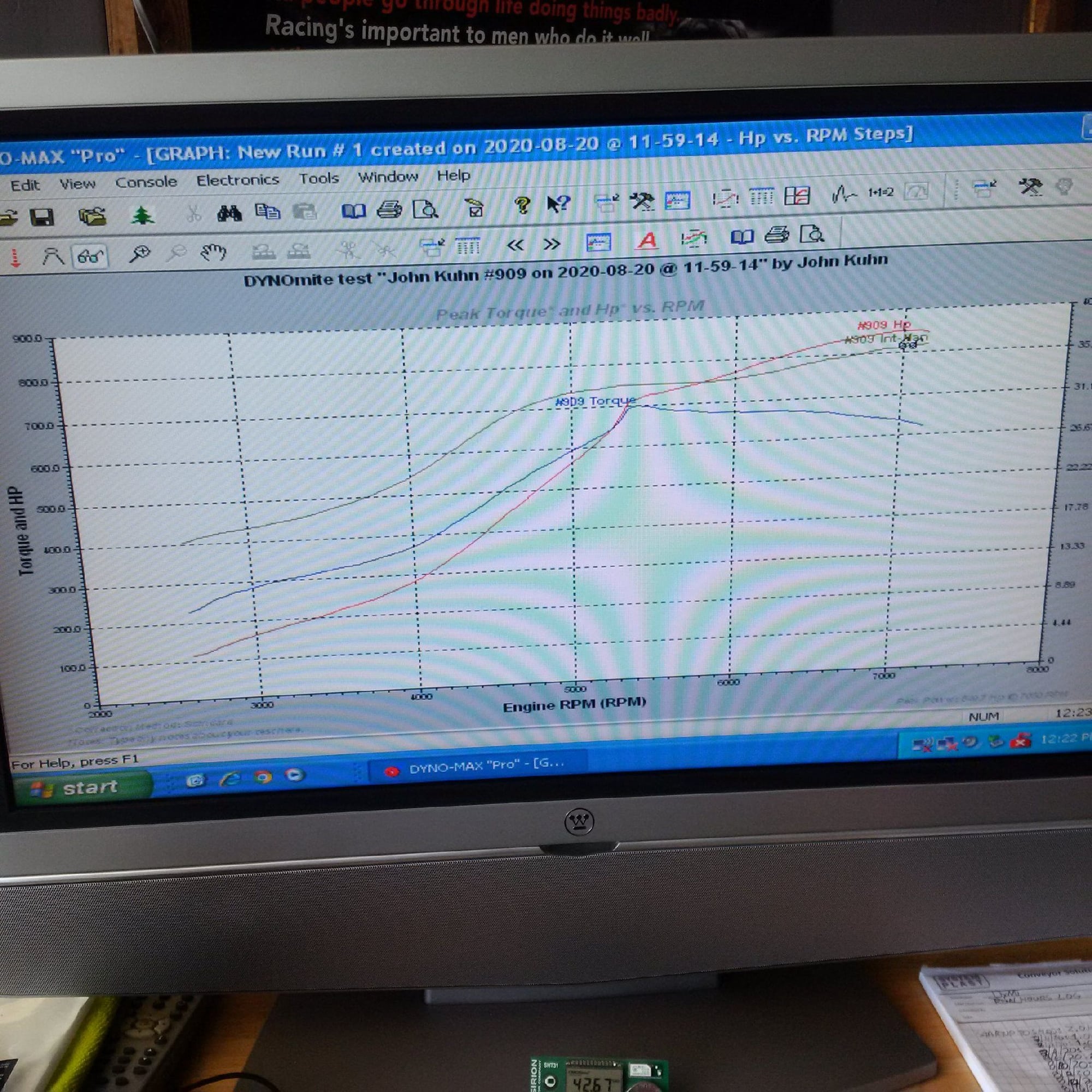
In any case, just a little bit of boost ramp up after 6000 rpm gives 850 rwhp already at 7000 rpm:
Thanks for the kudos on the car, I�ll convey them to John Kuhn. I enjoy technical chats on strategies...
Originally Posted by Thom
You may want to compare this % with other known engines not afflicted with such a restriction from the intake. 25% is enough of a drop to make the car not particularly enjoyable to drive, also considering how narrow the [peak torque rpm; peak hp rpm] window is. It is about time you drive your car and see for yourself what matters in terms of drivability - aiming for the lowest torque drop within the widest possible [peak torque rpm; peak hp rpm] window is the way to make a pretended "high revving, performance street engine" most efficient and most enjoyable to drive. You used to insist about making huge torque down low until learning it the hard way and breaking the transmission.
I understand you can boost your away around the intake restriction but this is not efficient, even if the engine may handle it for a short time.
I stress that these considerations, which are only my 2 cents worth anyway, do not question in any way the most excellent work that has been done on this project, but to me it seems you have reached with the intake a hardware limitation you will not be able to work around efficiently without making a new intake.
Edited to add : if the exhaust restrictions are as bad as you describe then a better intake is certainly going to alter the balance of restrictions and make the exhaust more restrictive than it is. From this point of view I agree that there is not much more to do than leaving the hardware the way it is.
This engine has a mildly ported intake manifold that improves the balance between cylinders. It's not the "ultimate" porting job in terms of equalizing the steady state "flow bench" flow across runners, but it's pretty good.
Glad to hear it, and I appreciate all the info/insight.
By efficiency I mean a boost to back pressure ratio close to 1 and corresponding "low" EGT readings.
Observing the turbochargers� temperature specification is definitely something that we have to do when setting limits to this. That I fully agree with.
The boost to bank pressure ratio I�m not so sure about. These cams are small (big for 928, but small for a generic four valve engine), so I�m not too worried about that ratio _provided_ that the gas exchange still works.
Originally Posted by SwayBar
Glad to hear it, and I appreciate all the info/insight.
Thanks. It�s been an interesting science experiment so far. For example, how else do you find how the 928 A/C compressor reacts to repeated 8000 rpm pulls and decelerations if you don�t try it?
Is there something in the tune which would explain why the torque curve suddenly changes shape at ~5400 rpm?
I find the whole shape of the curve intriguing, for its derivative is not negative up until peak torque rpm... is the brown line the boost level?
Is there something in the tune which would explain why the torque curve suddenly changes shape at ~5400 rpm?
I find the whole shape of the curve intriguing, for its derivative is not negative up until peak torque rpm... is the brown line the boost level?
It�s a boost control thing related to the control algo and the sensor lags. Once the mapping is done and final profiles are calibrated it�ll be gone.
Right now, at high rpms the engine is seeing about 40 psia exhaust pressure with 35 psia intake pressure. It�s not race car �efficiency� numbers, but better than what factory turbo cars did before about year 2015.
Right now, at high rpms the engine is seeing about 40 psia exhaust pressure with 35 psia intake pressure. It�s not race car �efficiency� numbers, but better than what factory turbo cars did before about year 2015.
Yes, this is a very good ratio.
Looking at the compressor map you posted earlier, you are now running GTX3582R rather than GTX3576R turbos?
Yes, this is a very good ratio.
Looking at the compressor map you posted earlier, you are now running GTX3582R rather than GTX3576R turbos?
I think I posted the wrong map to make the general point. The map on which the engine location drawn by hand is correct. These are gen 1 GTX 3576 R turbos with the smaller compressor covers and Tial 2853 0.82 A/R ss hot side, both modified.

 08-19-2020, 06:34 PM