When you click on links to various merchants on this site and make a purchase, this can result in this site earning a commission. Affiliate programs and affiliations include, but are not limited to, the eBay Partner Network.
Here's a quick interesting factoid about how much pressure 12+ psi really is. It's a lot. It's as much pressure as you experience if you stand two miles away from an atmospheric detonation of 250kt nuclear blast. The 12+ psi inner zone is associated with 98% human fatality rate, 2% non-fatal injury rate, and 0% non-casualty rate. The point being the forces per area we have in these boost pipes are incredible.
[13] Vulnerability of Population in Various Overpressure Zones
Source: The Effects of Nuclear War – Office of Technological Assessment, Congress of the United States, May 1979. Figure 1 – Vulnerability of Population in Various Overpressure Zones, p. 19.
[14] Approximate blast areas from 15kt, 20kt, 25kt, 108kt, 140kt, 160kt, and 250kt detonations. Area size was calculated using annulus.
Sources: Glasstone/Dolan, “The Effects of Nuclear Weapons,” Nuclear Bomb Effects Computer, 1976. The Nuclear Bomb Effects Computer was derived from, “Nuclear Bomb Effects Computer (including Slide-rule Design and Curve Fits for Weapons Effects)”, E. Royce Fletcher, Ray W. Albright, Robert F.D. Perret, Mary E. Franklin, I. Gerald Bowen, and Clayton S. White, Civil Effects Study CEX-62.2, U.S. Atomic Energy Commission, February 15, 1963. The graphs and equations for computing the effects of nuclear weapons, mostly based on extrapolations from Hiroshima data, have been available in the public domain since the 1960s.
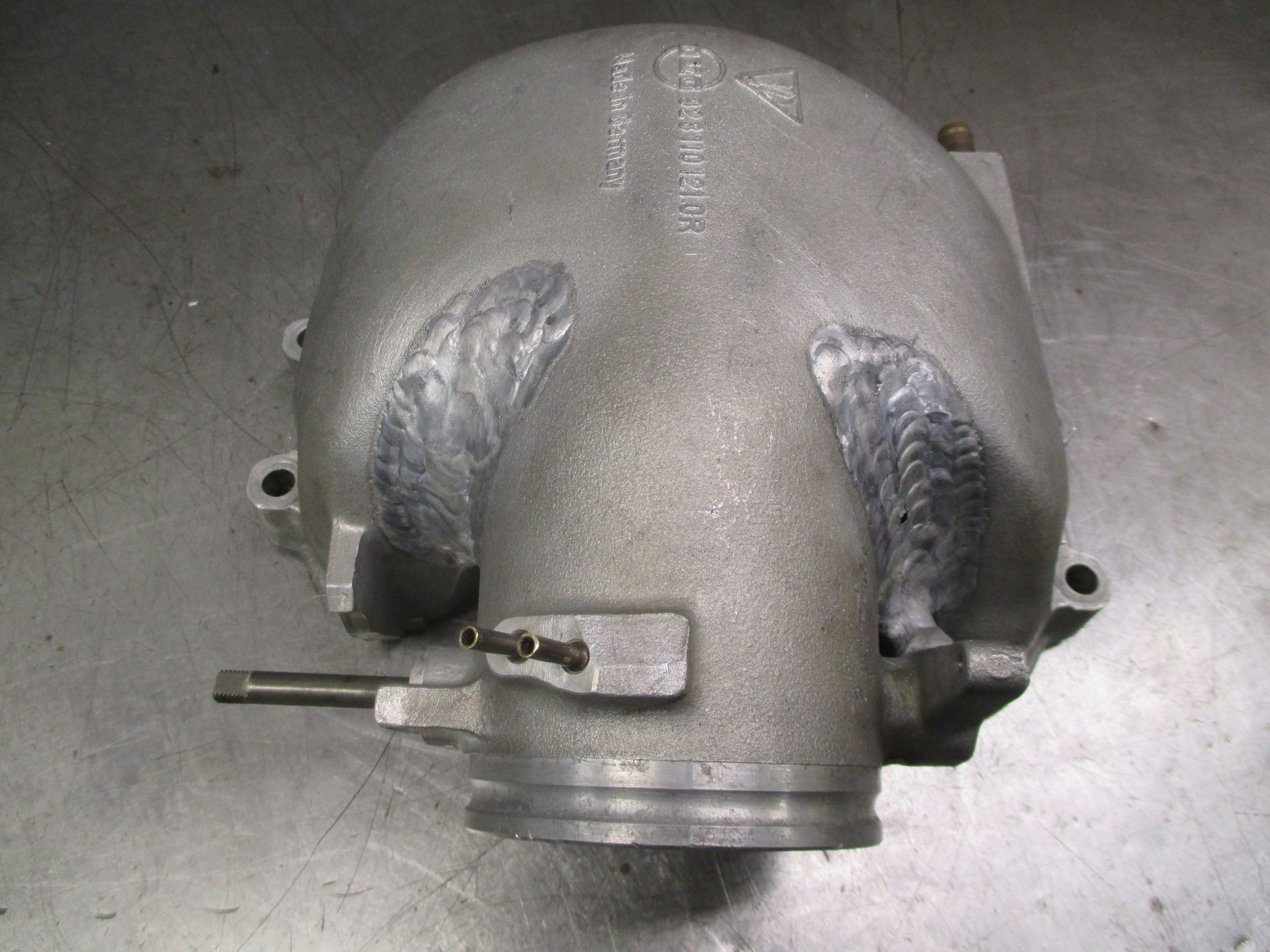
The infinity pipe is welded. The design includes two support rods. The two support rods serve two purposes. First, they reduce any resonances for sound and increase rigidity to prevent welds from fatiguing. Second, they make the construction a lot easier as the complex pipe retains it shape a lot better when welded if the support rods are in place:
Hi Guys, good to see progress is still being made with this endeavor.
Sadly I've passed on ownership of my 928. I've recently replaced it with the back end of a formula 1 car which I'm working on building back into a complete open wheeled racecar...
Keen to see your car back on the dyno and pumping out some big numbers.
Hi Guys, good to see progress is still being made with this endeavor. Sadly I've passed on ownership of my 928. I've recently replaced it with the back end of a formula 1 car which I'm working on building back into a complete open wheeled racecar... Keen to see your car back on the dyno and pumping out some big numbers.
It’s been slow going with the shop accident and second attempt at the center section. Getting there, though.
Also, I’ve had distractions. One of the people on my dissertation committee won the Nobel prize. Since my advisor won the Nobel prize a couple years back, there are now two people on my committee with that particular honor. Also, I bought a new car yesterday. Note the correct placement of intercooler heat exchangers:
None one of this is related to John’s exhaust work on the 928, but I figured I’d (over)share...
Also, I�ve had distractions. One of the people on my dissertation committee won the Nobel prize. Since my advisor won the Nobel prize a couple years back, there are now two people on my commuter with that particular honor.
Bet you're really looking forward to your orals...
It�s been slow going with the shop accident and second attempt at the center section. Getting there, though.
Also, I�ve had distractions. One of the people on my dissertation committee won the Nobel prize. Since my advisor won the Nobel prize a couple years back, there are now two people on my committee with that particular honor. Also, I bought a new car yesterday. Note the correct placement of intercooler heat exchangers:
None one of this is related to John�s exhaust work on the 928, but I figured I�d (over)share...
Like to know how the air is coming out of and its way of flow after the heat exchangers. Assume the heat exchangers are not openly exposed to the front wheels and the dirt flying around in the front wheel housings. Pictures please.
�ke
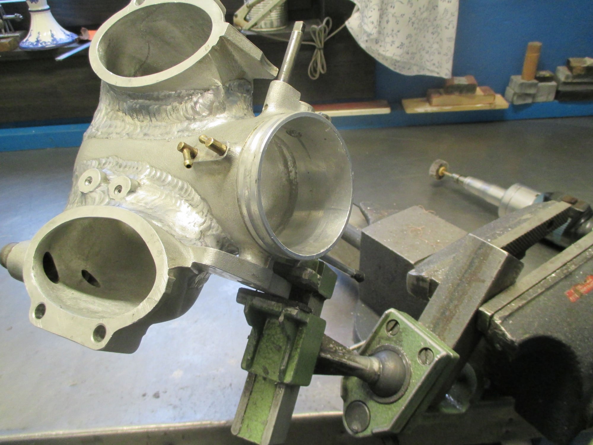
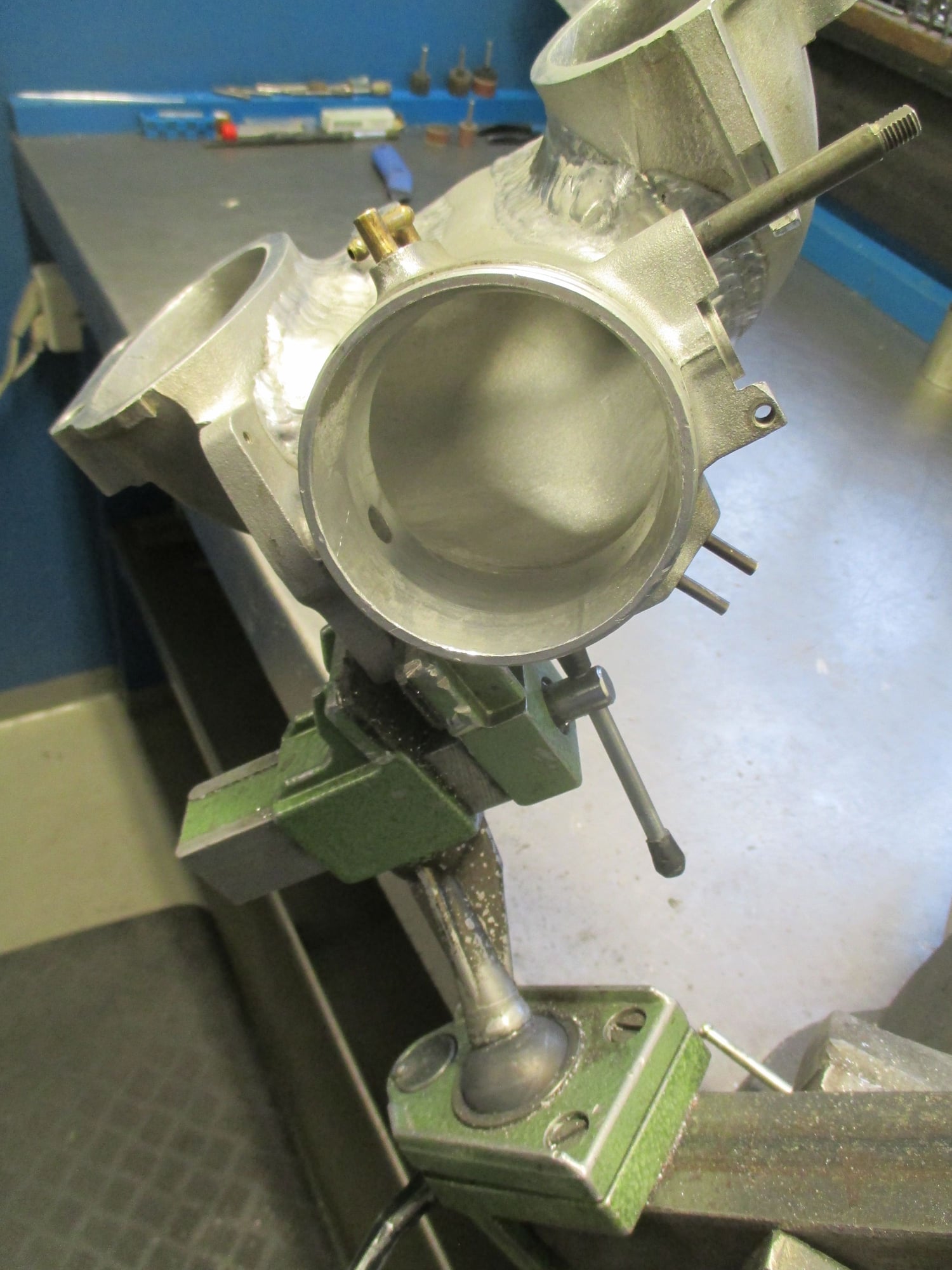
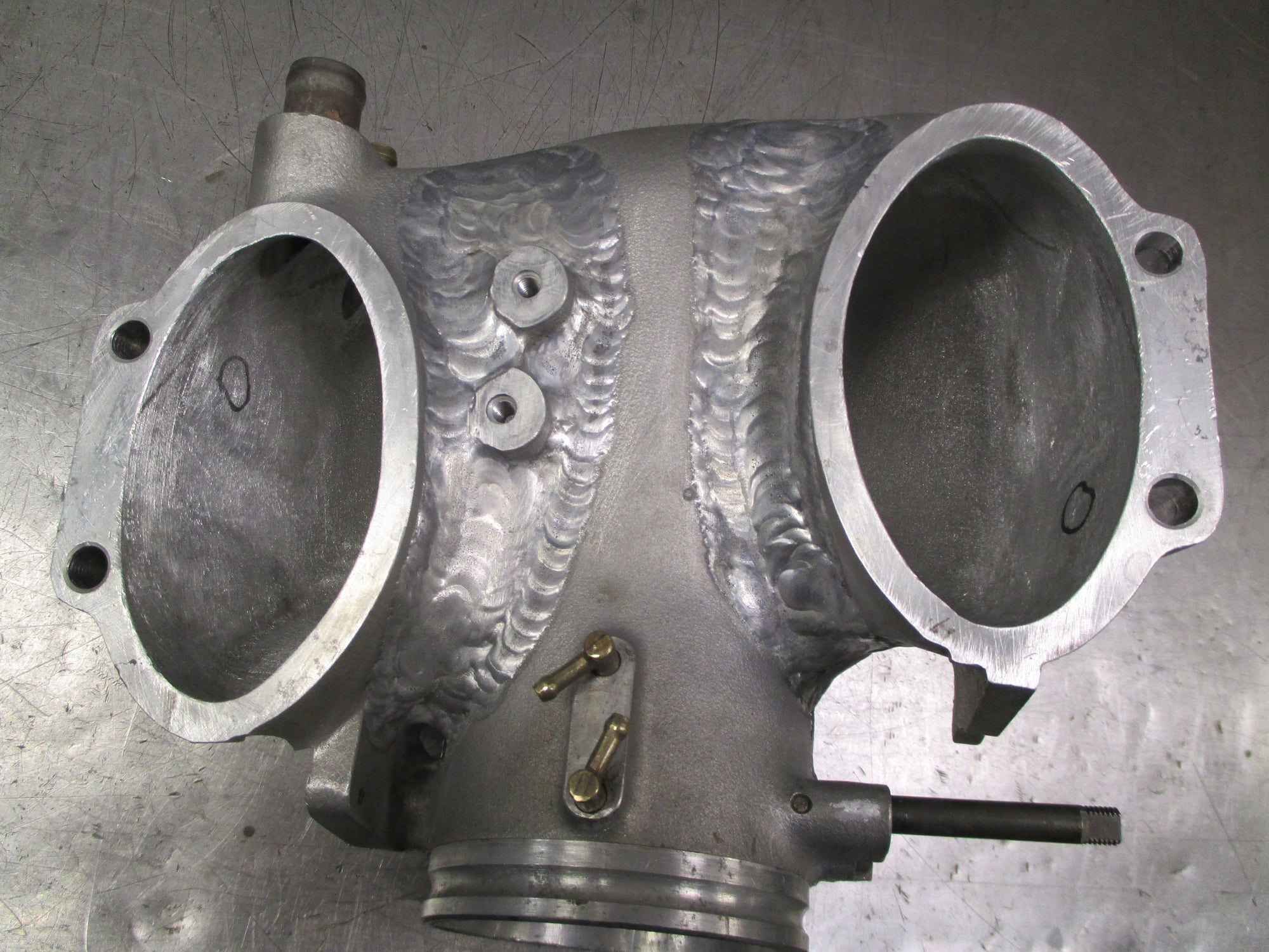
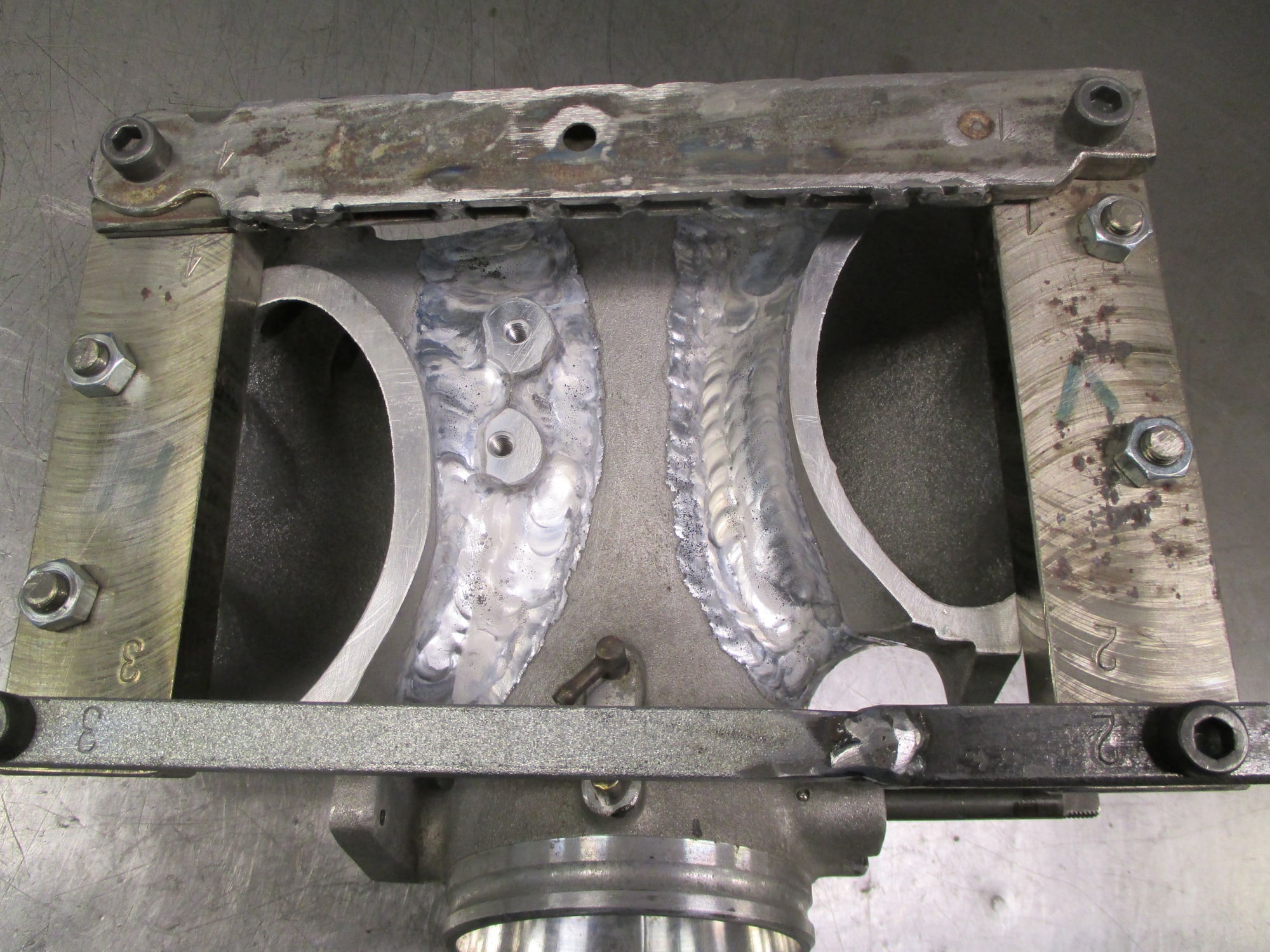
Temporarily moving from the exhaust side to the intake side
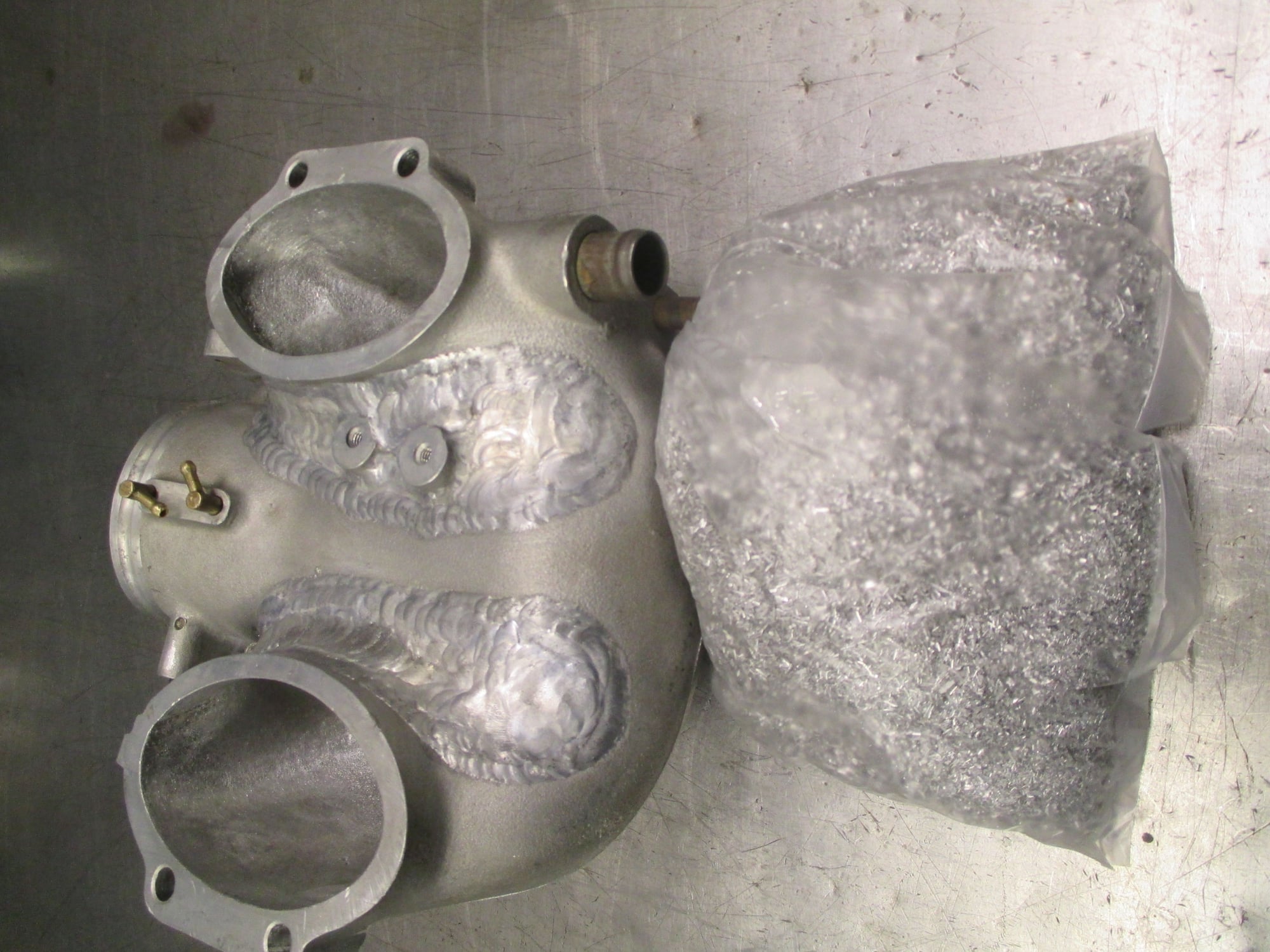
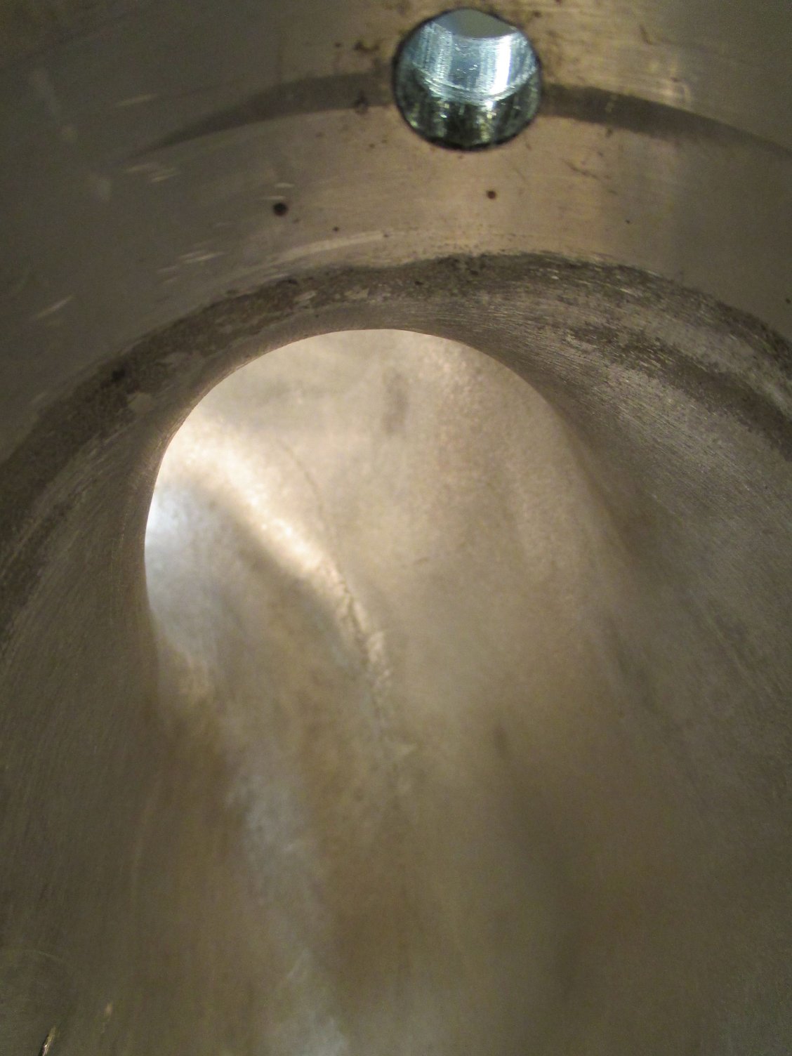
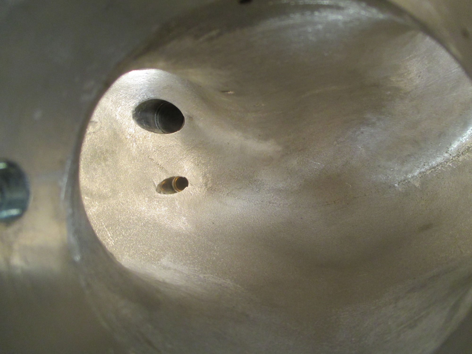
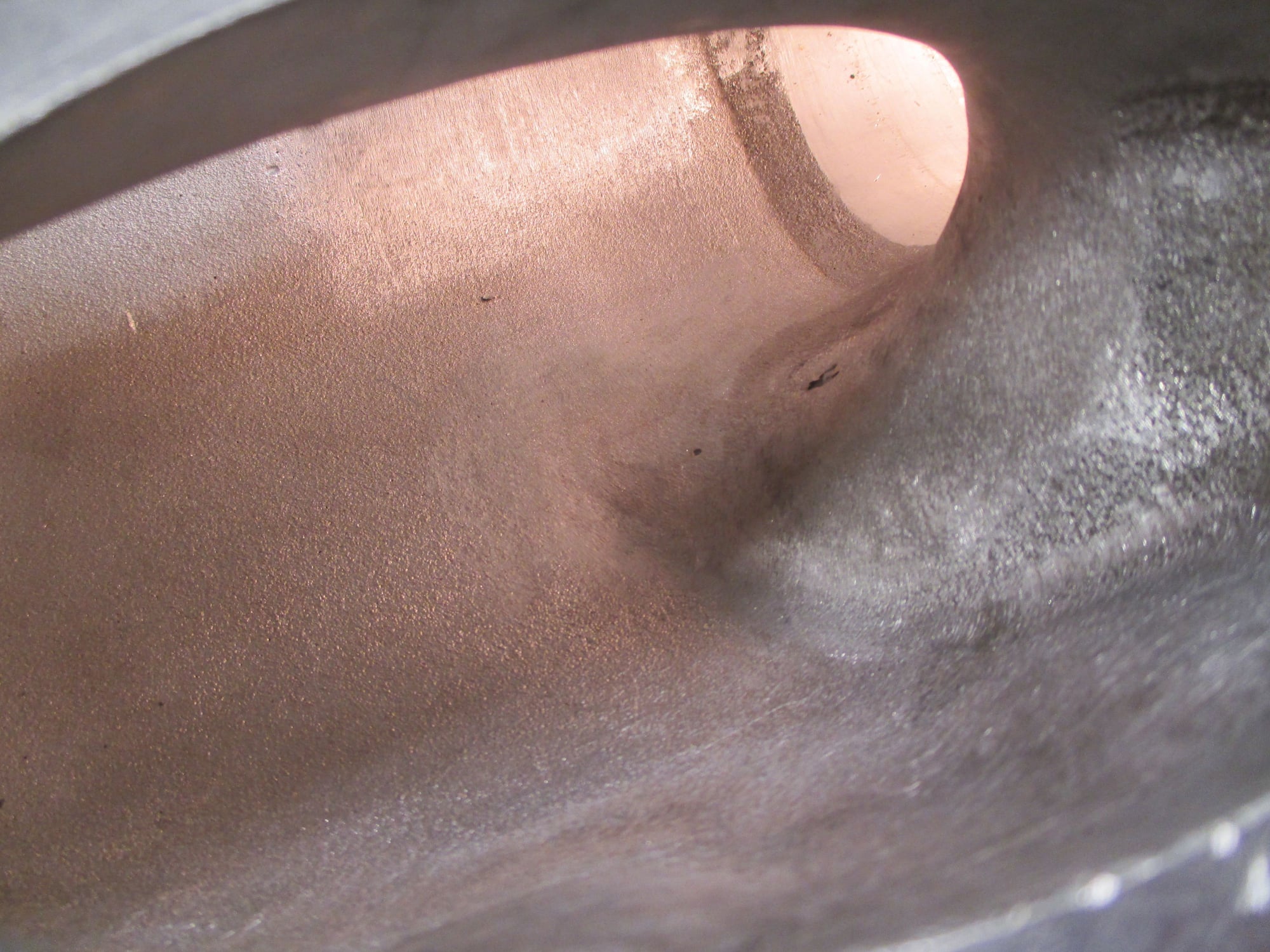
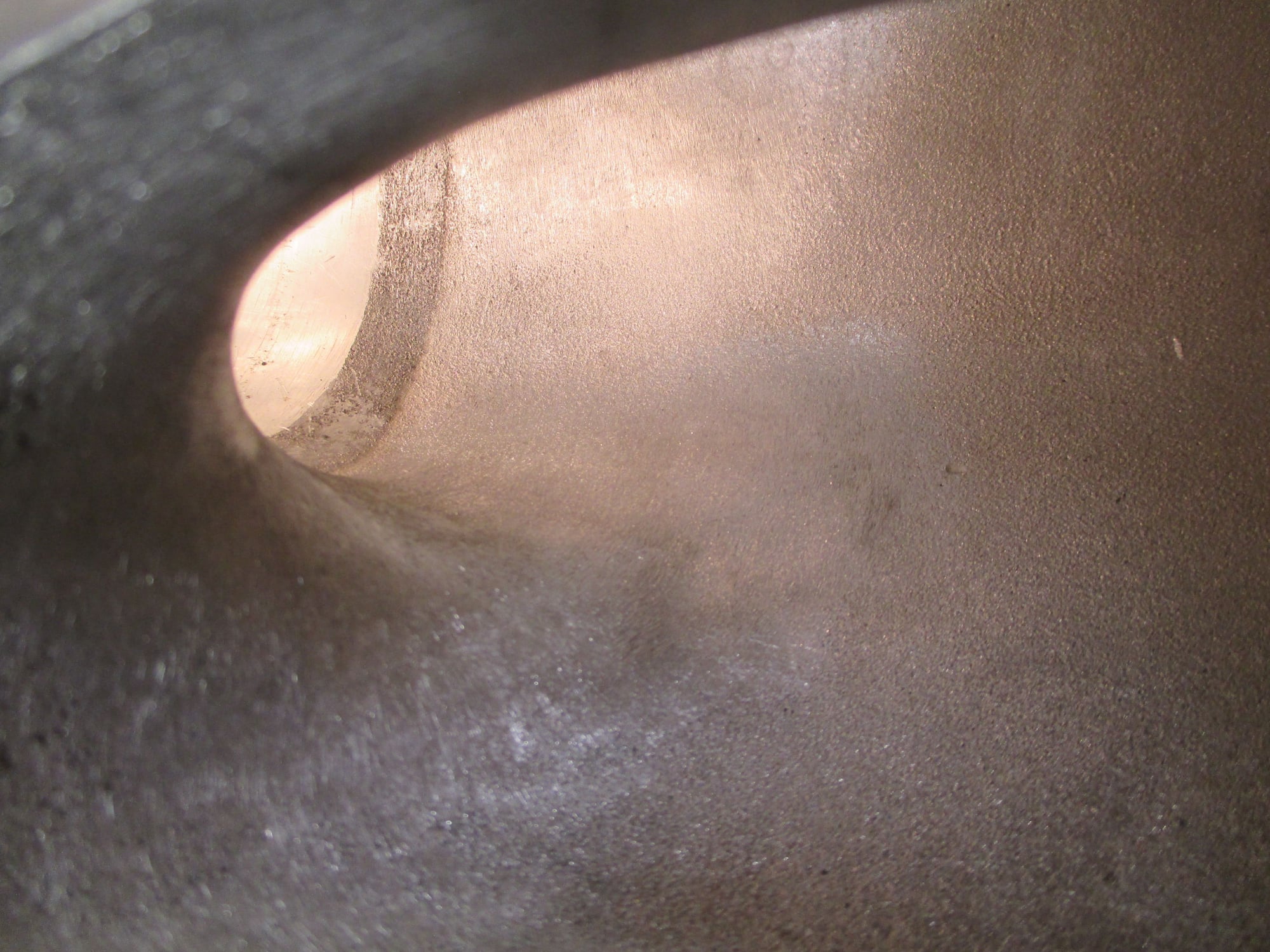
Ake is doing some pretty involved porting work in Sweden on the throttle body element. This is a science experiment. The objective is to first find out how much one can get the stock throttle body element to flow. Once the maximum flow is established, the second objective is to figure out how to get very near to that maximum flow with minimum modifications.
If anyone wants to sell us an additional S4+ throttle body or two at a reasonable price, we'll buy them and sacrifice them on the altar of science.
Tuomo,
perhaps relevant to your interests...
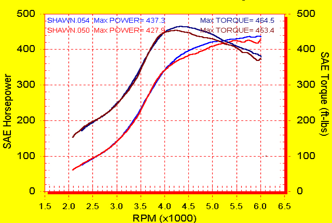
back to back dyno testing on a 3.0L 951 comparing stock ~55mm TB to a 65mm unit.
since TBs are a volume-control device i would think you could compare TB blade diameter (flow area) vs displacement.
going off that alone (3.0 with 65mm vs 5.0, but discounting the throttle shaft which maybe one shouldnt) suggests an 83mm TB for a 5.0 engine.
Another way to judge the throttle body diameter required is that the square of the required diameter is probably proportional to horsepower * 14.7/(14.7 + boost in psi). Making 500 hp with 10 psi of boost is going to require a lot larger (blow thru) throttle body than making 500 hp with 20 psi boost. That�s largely independent of the engine displacement.
Originally Posted by V2Rocket
Tuomo,
perhaps relevant to your interests...
back to back dyno testing on a 3.0L 951 comparing stock ~55mm TB to a 65mm unit.
since TBs are a volume-control device i would think you could compare TB blade diameter (flow area) vs displacement.
going off that alone (3.0 with 65mm vs 5.0, but discounting the throttle shaft which maybe one shouldnt) suggests an 83mm TB for a 5.0 engine.

 10-03-2017, 08:45 PM