Twin Turbo 928 fixed and back out there terrorizing the streets!
 04-11-2014, 11:38 PM
#796
Nordschleife Master
Thread Starter
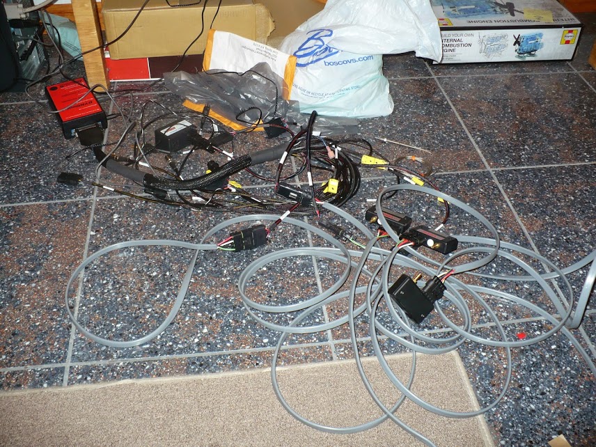
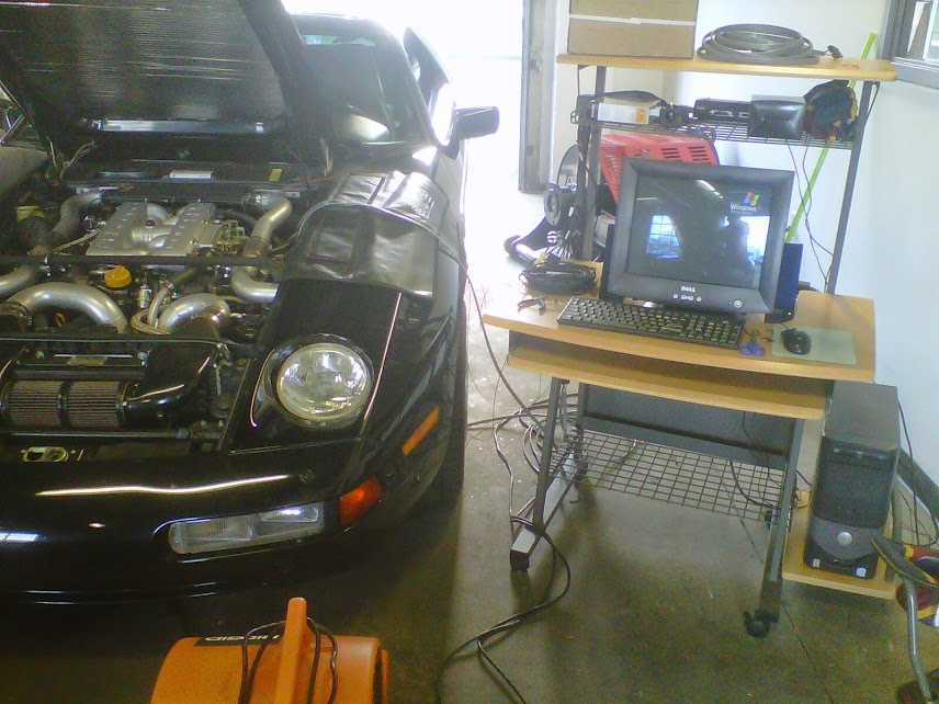
These sensors got strapped on (onto? work with me, I am straight off the boat) the car tonight. It's all normal "slow" sensors, but obviously enough to measure the cycle average pressures: the pressure at the compressor inlet, compressor outlet, after the intercooler, exhaust manifold, and the turbo downpipe. This will be enough to figure out whether all parts of the new turbo system are sized right, or if there's something that has to be changed to remove a significant restriction.
The temperature sensors are added next, one can't do the total energy (enthalpy) math without temperatures. There's energy in these pipes in three forms: static pressure, kinetic pressure, and heat. Pressure sensors place normal to the flow will pick up the static pressures. Kinetic pressure can be computed from the flow rates and cross-sectional areas. The heat has to be measured with a temperature sensor.
After that, it'll be time for the fast sensors.
Last edited by ptuomov; 04-12-2014 at 08:21 PM.
 04-13-2014, 11:11 AM
#797
Nordschleife Master
Thread Starter
John did a ton of work figuring out what is going on with the cold side of the new turbos. His objective has been to size all the components just right, not too small, not too large, but just right like Goldilocks would want them. This is especially critical when space is at such a premium, one does not want to have a pipe in there that is either smaller or larger than necessary.
So far, all indications are that the cold side is sized consistently.
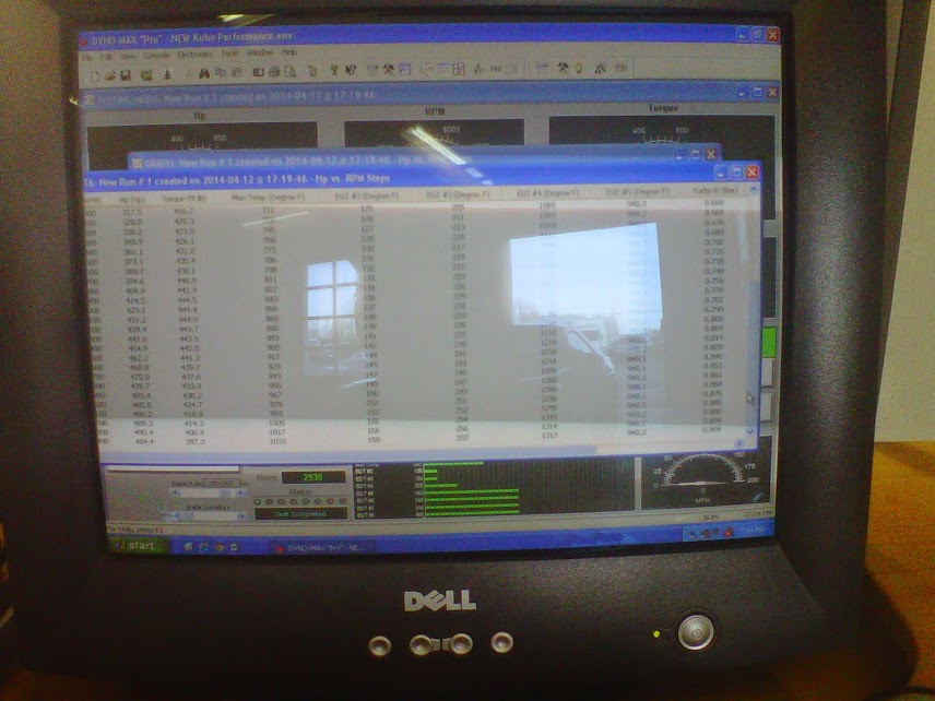
Here's an example of what kind of data we're looking at on the cold side. This is for the engine at 6000 rpm, 5L displacement, and assumed volumetric efficiency of 90%. Boost setting is still low at about 9 psi and the car is putting out slightly under 500 rwhp at that 6000 rpm, while the peak is slightly above 500 rwhp at 6400 rpm. The ambient pressure was about 14.5 psia and temperature in the shop slightly under 80F. All the turbo data below will need to be multiplied by two because there are two turbos.
Our first guess is that the compressor is operating at 66-72% efficiency. If we increase mass flow and boost (and believe me, we will) the compressor efficiency will actually increase. The new turbos were designed for higher boost and flow levels.
Our best estimate is that the turbine inlet is seeing 1-2 Hg of vacuum because of the air cleaners and the routing of the pipes. That causes the compressor inlet pressure to be 13.6 psia inlet density 0.068 lb/ft3.
After the compressor works it magic spinning at about 90,000 rpm, the compressor outlet sees 11.3 psig (in excess of ambient) pressure with the pressure increasing by about 12.2 psi between inlet and outlet. The outlet air temperature is about 250F, which puts us around 70% compressor efficiency. The compressor pressure ratio, "P2/P1", is 1.91 and the outlet density 0.099 lb/ft3.
Next, we run the air thru the fender mounted air to air intercoolers. These are ventilated with a 1600 CFM fan each, but nothing is sprayed on them. Compared to the street driving conditions, we believe the air flow is below where we actually expect it to be car at speed and the wheel motion pulling a low pressure in the wheelwell. After the intercooler, measured in the stock intake manifold inlet, the pressure is 8.8 psig (relative to ambient), the air temperature is now 150F and density 0.103 lb/ft3. The pressure drop due to pipe turns and the intercoolers is approximately 2.5 psi. For that 2.5 psi drop, we are getting intercooler effectiveness of (250F -150F)/(250F-80F) or 59%.
The actual compressor air flow is 24.4 lb/min, which by a rule of thumb would correspond with a hp estimate of 513 hp. That's just a rule of thumb, it's a useful sensibility check but we don't need it since the car is strapped on a dyno - we know the real figure. To put us on a compressor map, we need to factor in the pressure correction of 0.972 and temperature correction of 0.995, which means we should be located on the compressor map somewhere at x=25.0 lb/min, y =1.91.
That's our current view of what is happening on the cold side.
The next step is to get more measurements to try to poke holes in this view and to find inconsistencies which are either caused by measurement errors (leading us to improve measurements) or by misunderstanding (leading us to rethink what is going on). in particular, the following need to be measured in multiple ways and consistency confirmed:
1. We think that the compressor pressure ratio is 1.91. We can rearrange some sensors and get this pressure ratio measured as cleanly as possible.
2. Actual mass flow rate per turbo from assumed VE 90% at 6000 rpm is 24.4 lb/min and corrected mass flow rate is 25 lb/min. We can go to the Sharktuner logs and look at the MAF voltage and translate that to lb/min units to confirm that mass flow rate.
3. Turbocharger speed inferred from the compressor map, 1.91 pressure ratio, and corrected air flow of 25 lb/min is about 85k. We're observing something over 90k, but that's by looking at the gauge. The kink here is that Garrett doesn't publish a compressor map specifically for this cover and John has further modified the cover so we can't take the compressor map as gospel.
4. The compressor efficiency inferred from the 80F to 250F temperature rise is 66% and that inferred from the map using 1.91 PR and 25 lb/min 72%. With the exact shaft speed figures, we'll be able to narrow this down on the map.
We'd be most grateful if anyone could poke holes to our understanding of how the cold side works, although I don't expect us to have to majorly revise this view.
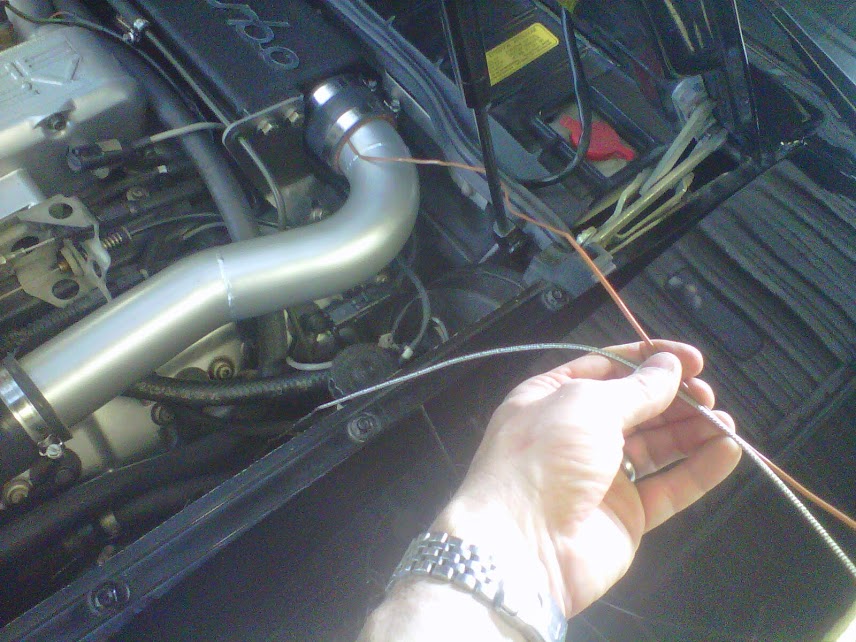
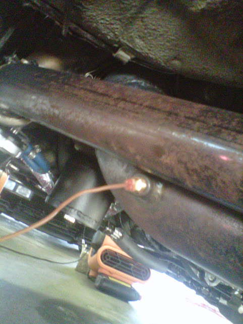
Here's an obligatory photo of John debugging the exhaust tract temperature sensors:
So far, all indications are that the cold side is sized consistently.
Here's an example of what kind of data we're looking at on the cold side. This is for the engine at 6000 rpm, 5L displacement, and assumed volumetric efficiency of 90%. Boost setting is still low at about 9 psi and the car is putting out slightly under 500 rwhp at that 6000 rpm, while the peak is slightly above 500 rwhp at 6400 rpm. The ambient pressure was about 14.5 psia and temperature in the shop slightly under 80F. All the turbo data below will need to be multiplied by two because there are two turbos.
Our first guess is that the compressor is operating at 66-72% efficiency. If we increase mass flow and boost (and believe me, we will) the compressor efficiency will actually increase. The new turbos were designed for higher boost and flow levels.
Our best estimate is that the turbine inlet is seeing 1-2 Hg of vacuum because of the air cleaners and the routing of the pipes. That causes the compressor inlet pressure to be 13.6 psia inlet density 0.068 lb/ft3.
After the compressor works it magic spinning at about 90,000 rpm, the compressor outlet sees 11.3 psig (in excess of ambient) pressure with the pressure increasing by about 12.2 psi between inlet and outlet. The outlet air temperature is about 250F, which puts us around 70% compressor efficiency. The compressor pressure ratio, "P2/P1", is 1.91 and the outlet density 0.099 lb/ft3.
Next, we run the air thru the fender mounted air to air intercoolers. These are ventilated with a 1600 CFM fan each, but nothing is sprayed on them. Compared to the street driving conditions, we believe the air flow is below where we actually expect it to be car at speed and the wheel motion pulling a low pressure in the wheelwell. After the intercooler, measured in the stock intake manifold inlet, the pressure is 8.8 psig (relative to ambient), the air temperature is now 150F and density 0.103 lb/ft3. The pressure drop due to pipe turns and the intercoolers is approximately 2.5 psi. For that 2.5 psi drop, we are getting intercooler effectiveness of (250F -150F)/(250F-80F) or 59%.
The actual compressor air flow is 24.4 lb/min, which by a rule of thumb would correspond with a hp estimate of 513 hp. That's just a rule of thumb, it's a useful sensibility check but we don't need it since the car is strapped on a dyno - we know the real figure. To put us on a compressor map, we need to factor in the pressure correction of 0.972 and temperature correction of 0.995, which means we should be located on the compressor map somewhere at x=25.0 lb/min, y =1.91.
That's our current view of what is happening on the cold side.
The next step is to get more measurements to try to poke holes in this view and to find inconsistencies which are either caused by measurement errors (leading us to improve measurements) or by misunderstanding (leading us to rethink what is going on). in particular, the following need to be measured in multiple ways and consistency confirmed:
1. We think that the compressor pressure ratio is 1.91. We can rearrange some sensors and get this pressure ratio measured as cleanly as possible.
2. Actual mass flow rate per turbo from assumed VE 90% at 6000 rpm is 24.4 lb/min and corrected mass flow rate is 25 lb/min. We can go to the Sharktuner logs and look at the MAF voltage and translate that to lb/min units to confirm that mass flow rate.
3. Turbocharger speed inferred from the compressor map, 1.91 pressure ratio, and corrected air flow of 25 lb/min is about 85k. We're observing something over 90k, but that's by looking at the gauge. The kink here is that Garrett doesn't publish a compressor map specifically for this cover and John has further modified the cover so we can't take the compressor map as gospel.
4. The compressor efficiency inferred from the 80F to 250F temperature rise is 66% and that inferred from the map using 1.91 PR and 25 lb/min 72%. With the exact shaft speed figures, we'll be able to narrow this down on the map.
We'd be most grateful if anyone could poke holes to our understanding of how the cold side works, although I don't expect us to have to majorly revise this view.
Here's an obligatory photo of John debugging the exhaust tract temperature sensors:
Last edited by ptuomov; 04-13-2014 at 11:20 PM.
04-13-2014, 12:33 PM
#798
This is a very small point, but you mention the wheel motion creating a vacuum at road speeds. Many cars trap high pressure air in the wheel-well area. I'm not sure how it correlates to the 928, but certainly at higher speeds the front of the tire should have some sort of high pressure zone in front of it I would think. Perhaps when you do all your studies that will affect your intercooler efficiency calculations (for temperature not flow I realize).
I'm also a tiny bit surprised you have as much pressure drop through charge piping and intercooler considering you haven't "turned up the wick" yet. I've seen many shoot for no more than 2.5 psi pressure drop at max hp. Then again, most people aren't having to deal with an engine bay as compact as this.
Good luck with your work; this is a constant pleasure to witness and probably the most thorough data gathering I've ever seen from a privateer.
04-13-2014, 12:50 PM
#799
Nordschleife Master
Thread Starter
I actually tested the wheelwell vacuum on Route 2, driving the care. A silicon hose taped inside the wheelwell in front of the wheel pulled a small but consistent vacuum relative to the pressure inside the car cabin. My highly sophisticated manometer + datalogger can't be fooled, I used my tongue to feel the vacuum! ;-)
Combine that with the stagnation pressure at the front bumper when the car is at speed, those intercoolers are going to flow a lot of air. At 100 mph, the stagnation pressure is ambient plus 0.17 psi, which is almost 5 inches of water. This intercooler duct is going to flow an enormous amount of air with 5" h2o pressure differential:
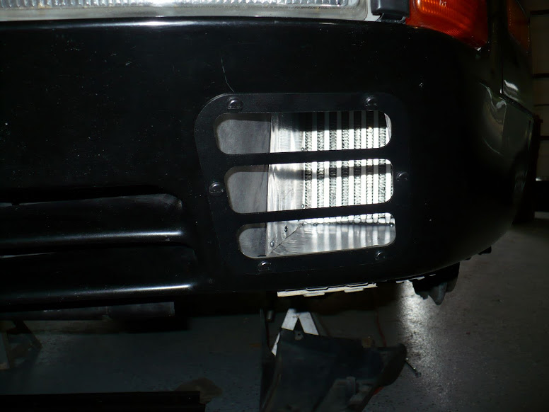
If you take a look at the photos earlier in the thread and the videos at "https: // www.youtube.com / user / HerrKuhn928", you'll see that nothing can be oversized and everything needs to be routed in a very constrained manner. 2.5 psi pressure drop is not unexpected, since we're looking at flow velocities of 170-180 fps in the inlet and outlet pipes. That said, we have to look at those pressure drops again when we run this at 25 psi at 6700 rpm in a couple of weeks (unless we've succeeded in destroying the stock engine before that).
I actually don't mind so much about the pressure drop after the intercooler inlet, I just want a low pressure drop up to the intercooler inlet. I want the hottest possible air in the intercooler to remove the most possible heat. After that, if the pressure drops a bit it just further cools the charge and since I am knock limited that's not a big loss.
Finally, a caveat. These are pressure sensors. Minor issues with the angle at which they are located relative to the flow can given very different temperatures. That's why we are not sure of anything at this point, it's all fuzzy and measured with error. Hence the need for as many alternative ways as possible to pin down what is happening inside the engine.
Credit really belongs to John. He's doing the heavy lifting. I am just doing some analytics.
Combine that with the stagnation pressure at the front bumper when the car is at speed, those intercoolers are going to flow a lot of air. At 100 mph, the stagnation pressure is ambient plus 0.17 psi, which is almost 5 inches of water. This intercooler duct is going to flow an enormous amount of air with 5" h2o pressure differential:
If you take a look at the photos earlier in the thread and the videos at "https: // www.youtube.com / user / HerrKuhn928", you'll see that nothing can be oversized and everything needs to be routed in a very constrained manner. 2.5 psi pressure drop is not unexpected, since we're looking at flow velocities of 170-180 fps in the inlet and outlet pipes. That said, we have to look at those pressure drops again when we run this at 25 psi at 6700 rpm in a couple of weeks (unless we've succeeded in destroying the stock engine before that).
I actually don't mind so much about the pressure drop after the intercooler inlet, I just want a low pressure drop up to the intercooler inlet. I want the hottest possible air in the intercooler to remove the most possible heat. After that, if the pressure drops a bit it just further cools the charge and since I am knock limited that's not a big loss.
Finally, a caveat. These are pressure sensors. Minor issues with the angle at which they are located relative to the flow can given very different temperatures. That's why we are not sure of anything at this point, it's all fuzzy and measured with error. Hence the need for as many alternative ways as possible to pin down what is happening inside the engine.
Credit really belongs to John. He's doing the heavy lifting. I am just doing some analytics.
This is a very small point, but you mention the wheel motion creating a vacuum at road speeds. Many cars trap high pressure air in the wheel-well area. I'm not sure how it correlates to the 928, but certainly at higher speeds the front of the tire should have some sort of high pressure zone in front of it I would think. Perhaps when you do all your studies that will affect your intercooler efficiency calculations (for temperature not flow I realize).
I'm also a tiny bit surprised you have as much pressure drop through charge piping and intercooler considering you haven't "turned up the wick" yet. I've seen many shoot for no more than 2.5 psi pressure drop at max hp.
Good luck with your work; this is a constant pleasure to witness and probably the most thorough data gathering I've ever seen from a privateer.
04-13-2014, 03:11 PM
#800
That's pretty funny about your vacuum measurement method...but hey if it works that's all that matters. Sounds like something I would do.
I completely understand about the packaging constraints (you've seen my thread). I just hope the pressures stay reasonable when you make 1.21 jiggawatts.
I wonder if you have enough sensor channels available if you could compare some of your temperature readings against a thermocouple on the outside of the aluminum piping. I would think the heat transfer is pretty quick and you can test at constant loads to give some time for temperature equalization from inside to out (or close enough anyway). Obviously it could be taped over to help isolate from ambient temperatures. I don't know this would be accurate enough to help much though...
04-13-2014, 03:37 PM
#801
Nordschleife Master
Thread Starter
I wonder if you have enough sensor channels available if you could compare some of your temperature readings against a thermocouple on the outside of the aluminum piping. I would think the heat transfer is pretty quick and you can test at constant loads to give some time for temperature equalization from inside to out (or close enough anyway). Obviously it could be taped over to help isolate from ambient temperatures. I don't know this would be accurate enough to help much though...
04-13-2014, 03:55 PM
#802
Electron Wrangler
Lifetime Rennlist
Member
Lifetime Rennlist
Member
I actually tested the wheelwell vacuum on Route 2, driving the care. A silicon hose taped inside the wheelwell in front of the wheel pulled a small but consistent vacuum relative to the pressure inside the car cabin. My highly sophisticated manometer + datalogger can't be fooled, I used my tongue to feel the vacuum! ;-)...
I think its great that you are instrumenting so thoroughly, some of this data will be quite useful beyond just your specific system tuning.
Alan
04-13-2014, 04:03 PM
#803
Nordschleife Master
Thread Starter
In terms of cabin pressures, I recall reading from somewhere that absent any efforts the car cabin tends to run below ambient pressures. That's a problem because dust tends to get sucked in. I think the first integrated fan/heater systems solved that. That's from some deep corner of my memory, so it might be all wrong.
04-15-2014, 07:19 PM
#804
Nordschleife Master
Thread Starter
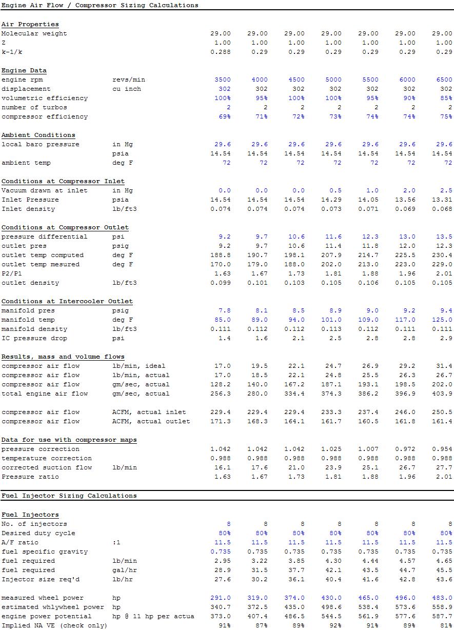
Here's a full set of my very simple cold side analytics calibrated from the sensor data acquired on the dyno. These are at max boost of 9 psi and with 500 rpm spacing.
Cold side:
John's still working on getting the exhaust pressure and temperature measurements correct. It's very tricky to know whether one is measuring the total (stagnation) pressure or static pressure or something in between with a particular sensor positioning in extremely space constrained environment. Similarly with temperature, total or static? Furthermore, it's tedious to keep track of which one it is in the formulas. I try to use total temperature always, and then static pressure if a measurement is taken and total pressure if no measurement is taken. Luckily, the temperature issue is not quantitatively large. If the exhaust is traveling at 0.3 Mach, static temperature of 1000F would translate to total temperature of 1022F, only a 22F increase. In principle, a thin probe inserted in the stream should get the total temperature, I think. In practice, since the sides cool it a bit, it will only get you maybe 80% of the difference. (I read wikipedia and stayed at Holiday Inn.) So a regular temperature sensor inserted in air flow that has static temperature of 1000F and total temperature of 1022F would register 1018F. Small potatoes, the difference between total and static temperature. The punch line is that the hot side analytics are going to take a little longer.
Last edited by ptuomov; 04-15-2014 at 10:39 PM.
04-16-2014, 09:17 PM
#806
Nordschleife Master
Thread Starter
04-20-2014, 10:19 AM
#807
Nordschleife Master
Thread Starter
Here's a dyno pull with with 12.5 psi and fast sweep. Fast sweep gives a more realistic torque curve for actual use, if we just hold and load the turbo will spool and the boost curve shifts to the left. What you want to do for evaluation (not tuning) is to replicate the assumed acceleration rates on various gears. At 12.5 psi, it's peaking at about 565 rwhp at 6400 rpm, indicating that we are benefiting significantly from higher gross power with relatively constant losses to mechanical inefficiencies.
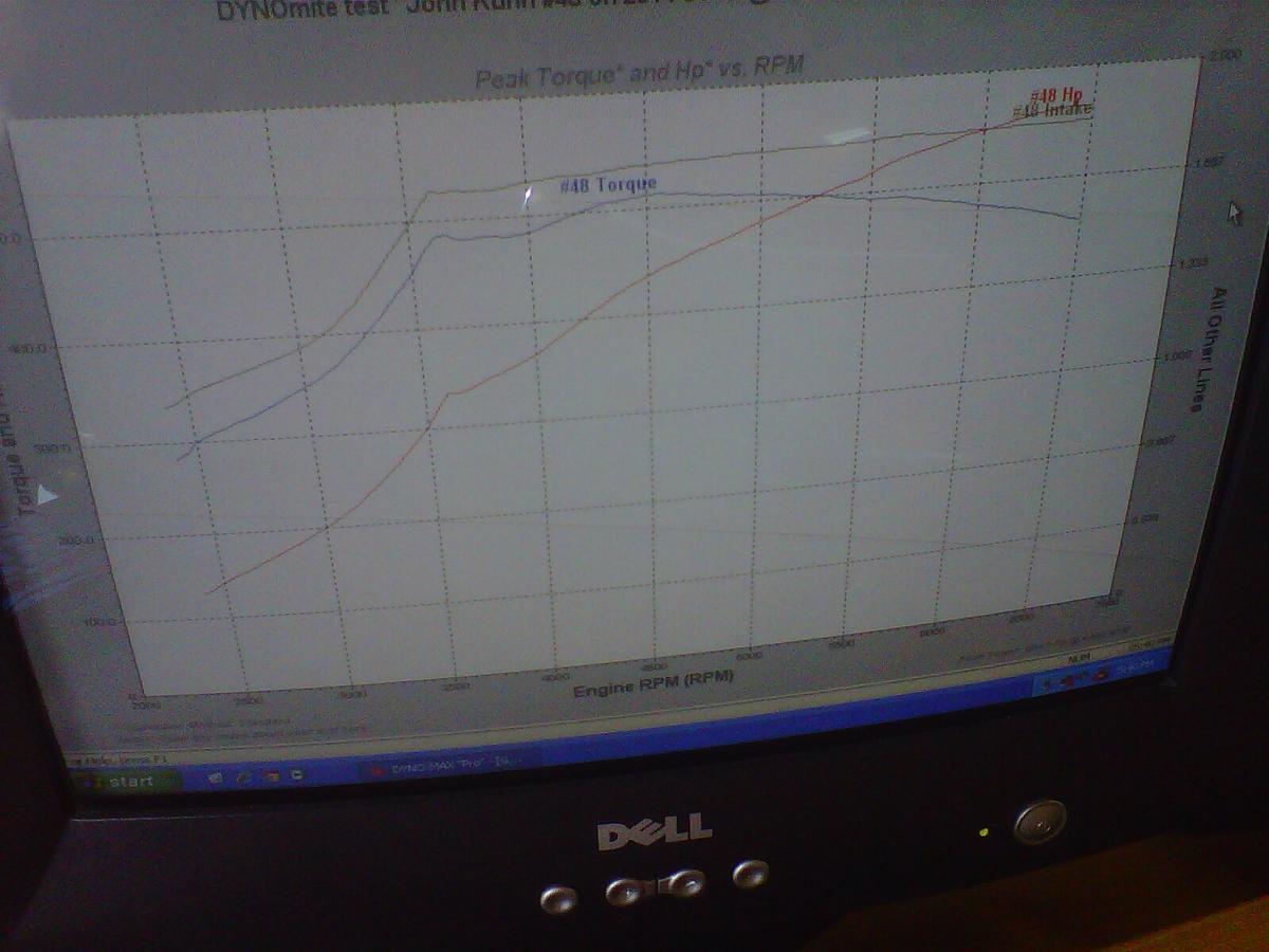
At about 105k turbo speed, there's much more headroom in the turbos. When we add boost and air mass flow, we'll still be moving to a slightly higher compressor efficiency island.
The hunt for bottlenecks and inefficiencies continues.
At about 105k turbo speed, there's much more headroom in the turbos. When we add boost and air mass flow, we'll still be moving to a slightly higher compressor efficiency island.
The hunt for bottlenecks and inefficiencies continues.
04-21-2014, 10:42 PM
#808
Nordschleife Master
Thread Starter
A quick update, later to be filed under the category "Mann tracht und Gott lacht":
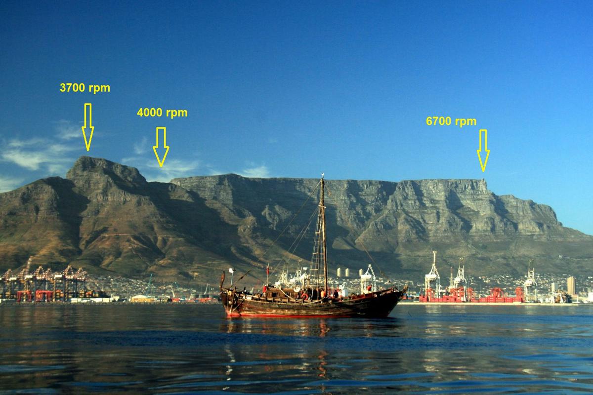
The next step is to increase boost at higher rpms, starting at about 5000 rpm. The objective is to flatten the "12.5 psi" torque curve in the earlier post to be about level at 500 rw ft-lbs up to 6700 rpm. The objective is to find out how much less we need to kick up the boost to flatten the torque curve with these new turbos, compared to the old turbos. The lower exhaust manifold back pressure should somewhat reduce the need to kick up the boost at high rpm. We might do another torque "curve" at a higher level, say 550 rw ft-lbs, to match the about 700 rwhp level that we reached with the old turbos. At this point, we should have ignition, fuel, and boost in the ballpark.
Graphical illustration of the torque curve we plan to produce on the dyno tomorrow:
After that, we'll do something more systematic. Above the 550 rw ft-lbs, we are likely to run to the knock constraint at least at some rpms with the 93 octane pump gas that we're optimizing this engine for. It's likely that we can reduce the ignition advance to get rid of knock, but this will reduce the torque and also will increase EGTs. EGT itself has a constraint, since the turbine can't take arbitrarily high temperatures.
This leads to us having to optimize the tune under two constraints: Knock constraint and the EGT constraint. The knock constraint is probably most sensibly stated in terms of knock probability or frequency and the EGT constraint in terms of total temperature. We are thinking about numbers like 0.1% or 0.05% of combustion events and 1650F EGT. From memory, the turbines are rated for 970C (1780F) continuous operation limit, if I recall correctly.
A simplified tuning problem is then the following. Maximize the torque by changing the AFR and ignition advance, given intake manifold pressure and rpm, subject to the knock constraint and the EGT constraints.
We'll be operating under the following assumptions about the functional forms (parameters being different in each pressure-rpm cell): We'll use a local, linear-quadratic approximation. In the relevant range, EGT is an increasing function of the AFR and a decreasing function of ignition advance. We'll make that locally linear. Knock probability is a decreasing function of AFR and an increasing function of ignition advance. We'll make that function locally linear as well. With the knock and EGT constraints satisfied and in the relevant range, torque is likely an inverted U-shaped function of AFR (with the peak at somewhere around 12.5-13 AFR based on previous life experience and intense studies of internet forums ;-) ) and an increasing function of ignition advance. We'll make torque a locally quadratic function of AFR and ignition advance.
I have no idea about the coefficient signs on the interaction terms AFR*ignition advance in the torque formula, so I did the first version of the optimization spreadsheet by assuming they are zeros.
The experiment itself that we are planning is controlled as follows. The dyno is set to hold a given rpm. Then, the boost controller is programmed to give some boost level. The engine is run at WOT and data are recorded with both the dyno data acquisition and ST2.
During the run, the fueling and ignition parameters are changed around the likely constrained optimum, sometimes inducing knock or high EGT by leaning the fueling. We'll also induce knock with high ignition advance and high EGT with low ignition advance.
Then, the data are copied to the spreadsheet we wrote and solver is used to solve for the suggested AFR and ignition advance under the local linear-quadratic assumptions. The analytical solutions are easy in Matlab but in Excel the matrix algebra is "a pain in the Tuchus" and Excel solver is actually pretty good.
Then the experiment is repeated around those suggested values, etc. Rinse and repeat.
What could go wrong with a plan like this? ;-)
04-22-2014, 03:04 AM
#809
I would assume that a certain margin for safety is a given (even if you are hell bent on blowing the motor), but might affect the strategy some, and here's why... I've used water methanol injection with some very impressive results in the past. What I learned is the real trick to controlling detonation was to stop it before it starts. I'm sure that has implications for piston, carbon, exhaust valve, or spark plug temperature. My point is that during a "power sweep", which replicates driving since steady state loads are unlikely, a bit of conservation on timing or AFR at lower rpm and around peak torque may prevent detonation from starting, and continuing, later on.
Another similar bit that you likely know is the difference between street and dyno pulling a motor for tuning. I know you're on a data mission, and it's a thrill to watch, but in lower gears (like you could use the power anyway) I'm sure the motor could get by with a a few degrees more timing or running a little more lean simply because you pass through the low rpm "danger zone" too quick for the engine parts to accumulate much heat and start detonation. I don't know if you have similar plans, but ms3 can determine what gear a manual transmission car is in by the vehicle speed sensor (this much speed must equal this gear at this many rpm). That could possibly be used to trigger table switching to run slightly more conservative maps in higher gears. Realistically this is all academic seeing as it's not really possible to use that kind of power in low gears.
I'm guessing you know this as well, but hooking a cheap audio amplifier straight to a bosch knock sensor with headphones on the other end is awesome for listening to detonation. Your ear can grab it before a computer while it's still in hysteresis of knock. You can even run the audio to a laptop and analyze and isolate the knock frequency with something like Gold Wave. Motec has a great article about this.
Something else I've wondered here... Since your collecting information about everything up to and including the astrological signs effect on power with your data acquisition, I would love to see some sort of effective pressure measurement at or near the intake port. For any naysayers (possibly including me) about the stock intake it would be fascinating to see any pressure loss (possibly quantified through a temperature drop) from the plenum to the intake port. If it indeed makes a difference, that may help balance out some of your calculated vs observed power offset.
04-22-2014, 08:23 AM
#810
Nordschleife Master
Thread Starter
Another similar bit that you likely know is the difference between street and dyno pulling a motor for tuning. I know you're on a data mission, and it's a thrill to watch, but in lower gears (like you could use the power anyway) I'm sure the motor could get by with a a few degrees more timing or running a little more lean simply because you pass through the low rpm "danger zone" too quick for the engine parts to accumulate much heat and start detonation.
I think that using the dyno sweep speed to simulate behavior at different gears is fairly accurate. With air-to-air intercoolers, knock probability should be slightly lower because of better cooling than with two 1600 CFM fans on the dyno.
I don't know if you have similar plans, but ms3 can determine what gear a manual transmission car is in by the vehicle speed sensor (this much speed must equal this gear at this many rpm). That could possibly be used to trigger table switching to run slightly more conservative maps in higher gears. Realistically this is all academic seeing as it's not really possible to use that kind of power in low gears.
First, we try to make the torque curves as flat as possible. This allows us to be closer to the traction limit than if there were a peak in the torque curve that would break the tires loose.
Second, we plan to program six different torque curves (each as flat as possible) at different levels. Eboost2 will allow me to select the first four of those profiles with two pins. The plan is to use microswitches from the shifter linkages to run lower torque program at lower gears. The details to be worked out.
I'm guessing you know this as well, but hooking a cheap audio amplifier straight to a bosch knock sensor with headphones on the other end is awesome for listening to detonation. Your ear can grab it before a computer while it's still in hysteresis of knock. You can even run the audio to a laptop and analyze and isolate the knock frequency with something like Gold Wave. Motec has a great article about this.
Something else I've wondered here... Since your collecting information about everything up to and including the astrological signs effect on power with your data acquisition, I would love to see some sort of effective pressure measurement at or near the intake port. For any naysayers (possibly including me) about the stock intake it would be fascinating to see any pressure loss (possibly quantified through a temperature drop) from the plenum to the intake port. If it indeed makes a difference, that may help balance out some of your calculated vs observed power offset.
I don't really care that much about pressure drop in the intake manifold due to poorly timed pressure waves. Why? Because when pressure drops, the charge cools.
Since this is a pump gas car on 93 octane fuel, we'll be knock limited for sure. The main determinant of knock is the intake charge temperature (with pressure also there in the formula, and two together determine density so maybe it's too heroic to say that one is the main determinant and two others less important -- but humor me.) When the pressure drops in the intake port due to a rarefaction wave, the charge cools. This allows us to run more boost at the compressor outlet, which then of course adds to the temperature at compressor outlet. The key is that the intercooler will take more heat out of the charge if we temporarily overpressurize. The cost is the turbo working harder, but that's often less costly than the gain from the ability to run more boost and/or timing. So with off-tune intake manifold, one can sometimes make more knock-limited power. The new and newish 911 turbos use that off-tune intake manifold cooling.
By the way, this "air cycle" is how air planes do air conditioning, since they have access to cold air flow. They use a turbo with air bearings in the middle:
.jpg)
http://en.wikipedia.org/wiki/Air_cycle_machine
But I digress...
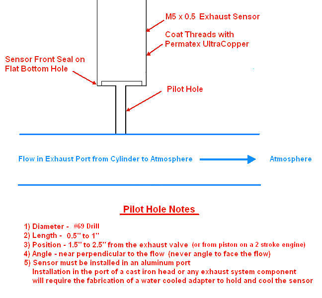
On the pressure measurement: Yes! In two months or so, we hope (springs eternal...) to have the capability to measure the intake port, combustion chamber, and exhaust port pressures with better than 1/4 degree resolution at the redline. The manifolds will be like Swiss cheese after go those sensors in.
We have to somehow solve the cooling problem for the exhaust port fast pressure sensor, however: