When you click on links to various merchants on this site and make a purchase, this can result in this site earning a commission. Affiliate programs and affiliations include, but are not limited to, the eBay Partner Network.
Struggling to understand what you have been doing with the MAF and ST2. When John came up wth his Super MAF as I understand he basically re-ranged the MAF, presumably using a different gauge platinum wire to overcome the limitations of the stock system wherein the LH could not longer read voltages from the MAF above a certain threshold thus creating more flow for a given voltage. Then in ST2 one gets the option to select the stock MAF or super MAF to tell the system how to interpret the inputs together with options for injector sizes so that fuelling can be optimised.
If I understand your current "need" presumably your problem was that you are producing so much power you have outstripped the range of the Super MAF- is that correct? If so, presumably you now have a patch that re-ranges the super MAF scaling without having to modify the MAF further?
SuperMAF is the physical sensor element including the housing. That component will go to about 1500hp or so before it pegs the 6.2V limit, although resolution may get worse at the top. I see no near term need for anyone to modify the SuperMAF.
Then, there's the question of what the LH software does with the SuperMAF signal. This is where the recent changes were made. Since this is all integer logic and as far as I know there's no native floating point arithmetic in LH, you want to scale everything such that you use almost the whole range. The previous version of the modified LH software from JDS scaled the MAF "signal" such that maps were limited to maximum load row definition of 300. In the experimental version, one is allowed to define rows up to 400.
Is version 400 strictly better than version 300? If you are never going over MAF signal of 300 (I don't think anyone else is there), then version 400 is worse for you than version 300, because resolution in the integer logic is slightly worse. If you are going over 300, then version 400 is better than version 300 because it allows you to explicitly adjust the map above load signal values over 300.
OK I get it. Folks with bigger motors were typically achieving up to around 600 rwhp so the MAF load signal range was set to cover that logically needed and no more. Now you have come along with your 650 rwhp presumably you are pushing the limit assigned to the software so another value range range has been added to better cover where you are at, the better question being where will your re-ranged software max out at?
OK I get it. Folks with bigger motors were typically achieving up to around 600 rwhp so the MAF load signal range was set to cover that logically needed and no more. Now you have come along with your 650 rwhp presumably you are pushing the limit assigned to the software so another value range range has been added to better cover where you are at, the better question being where will your re-ranged software max out at?
Row's can be freely defined, but the (new) hard limit is 400 MAF units. In terms of what the motor is potentially capable of using, MAF signal of 400 will be about the max needed on race gas for this engine based on our calculations.
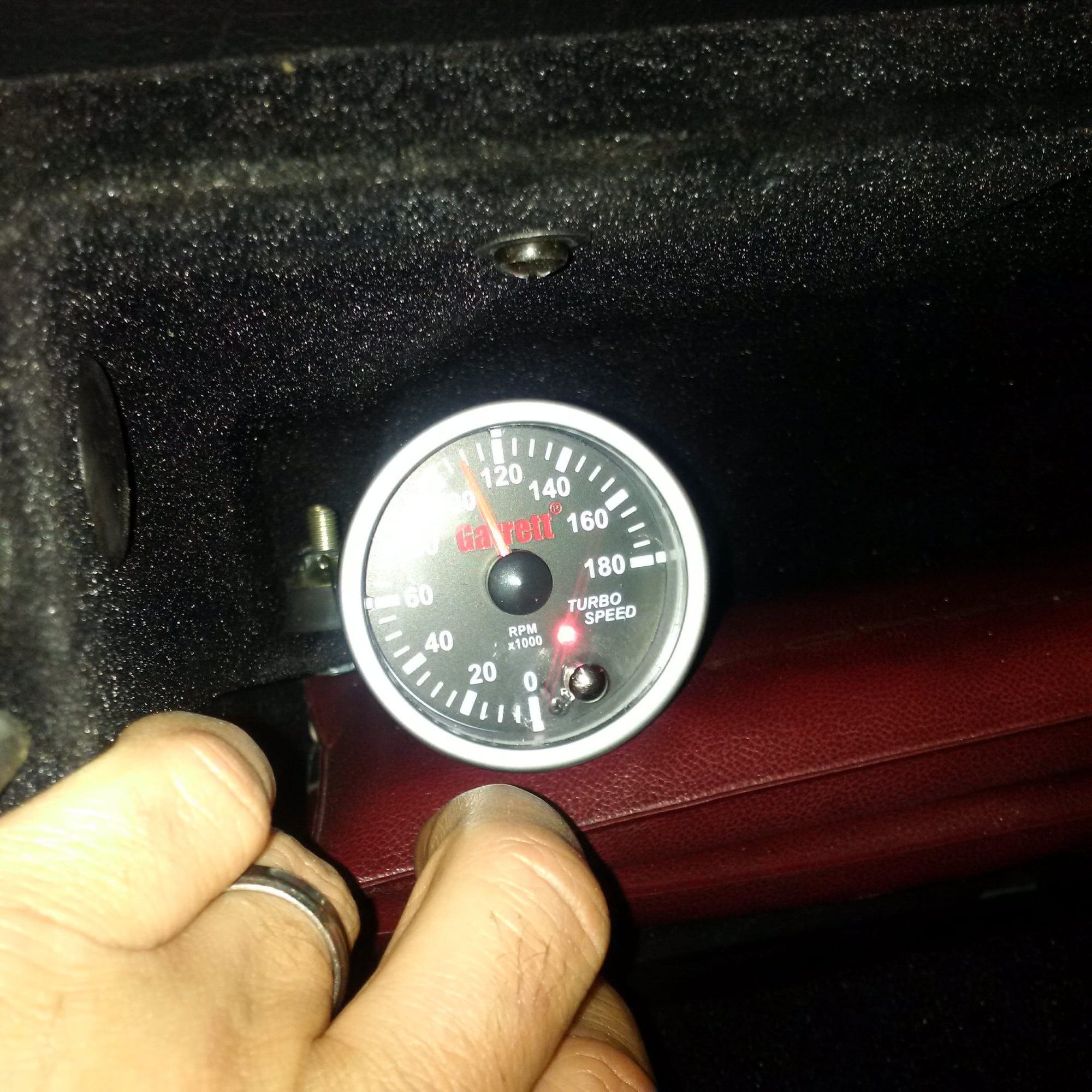
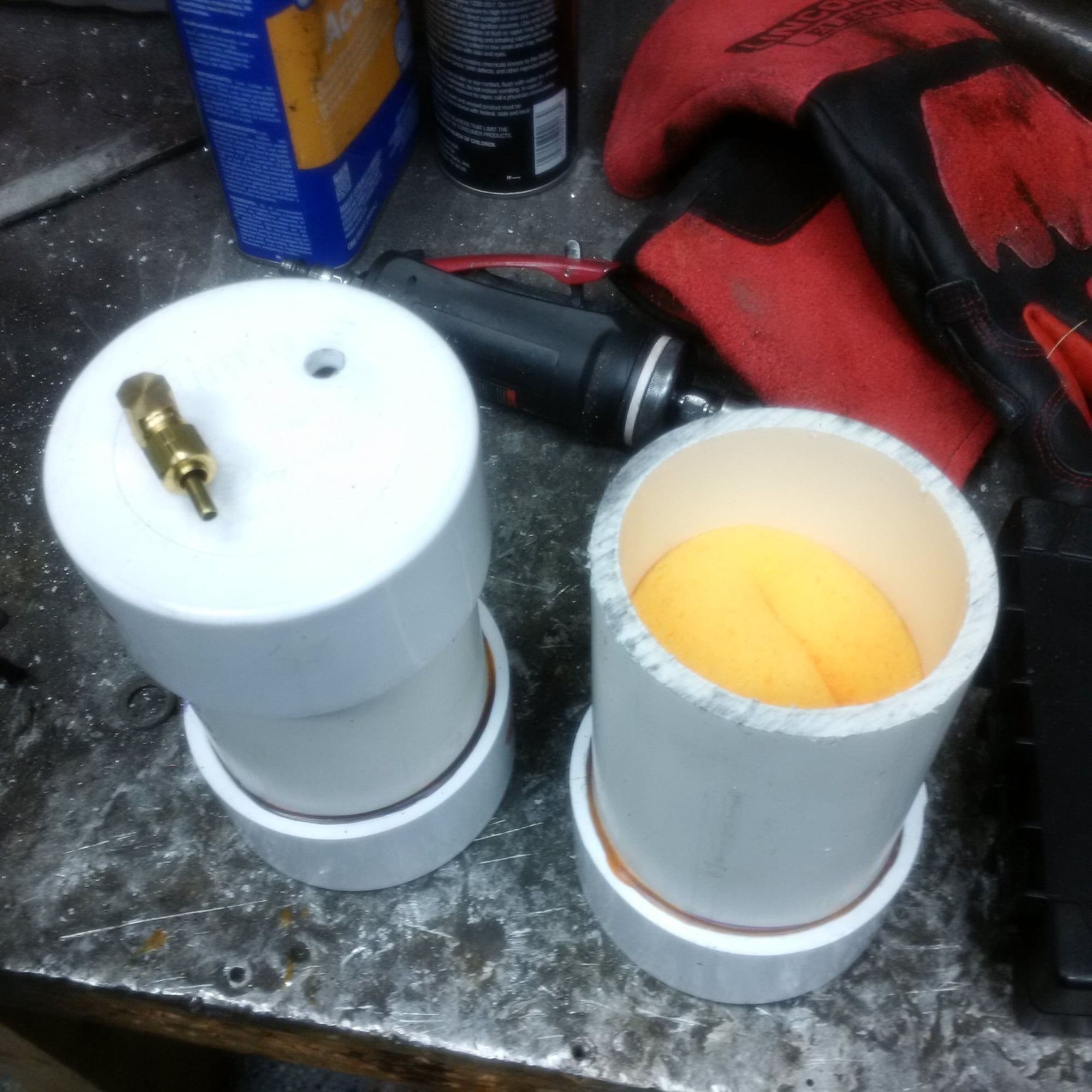
John fabricated some water traps for the slow pressure sensors, so now they don't boil on the dyno. The bung and line orientation is such that water accumulates on the lines.
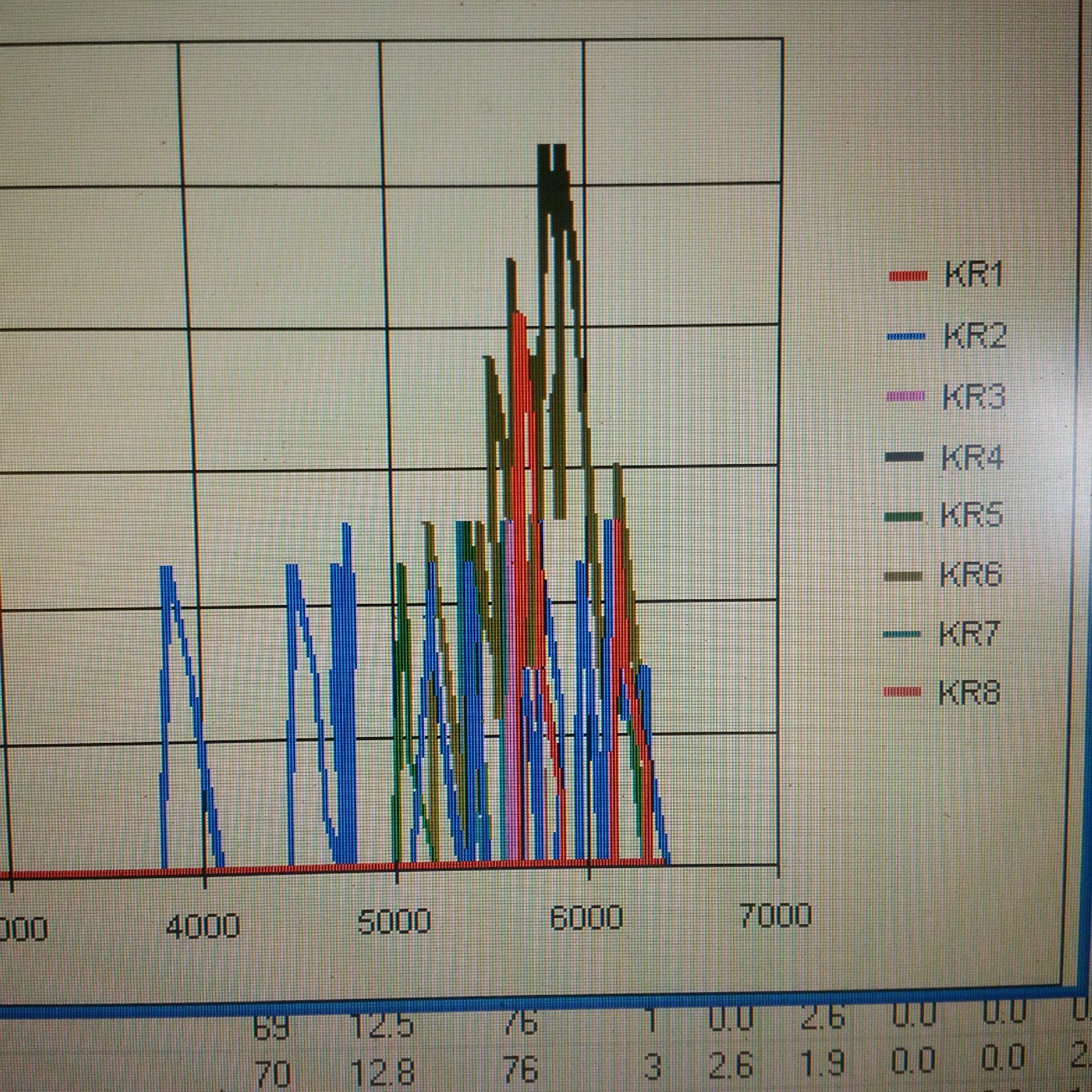
On the dyno, John intentionally induced some knocks to see what cylinders are knock prone with exhaust manifolds (not headers). At mid range, cylinder #2 sees most knocks. As predicted by the simulator, at 6000 rpm the most knock prone cylinders are #6 and #1 due to the 90-degree exhaust blowdown interference. You normally aspirated guys out there, install headers!
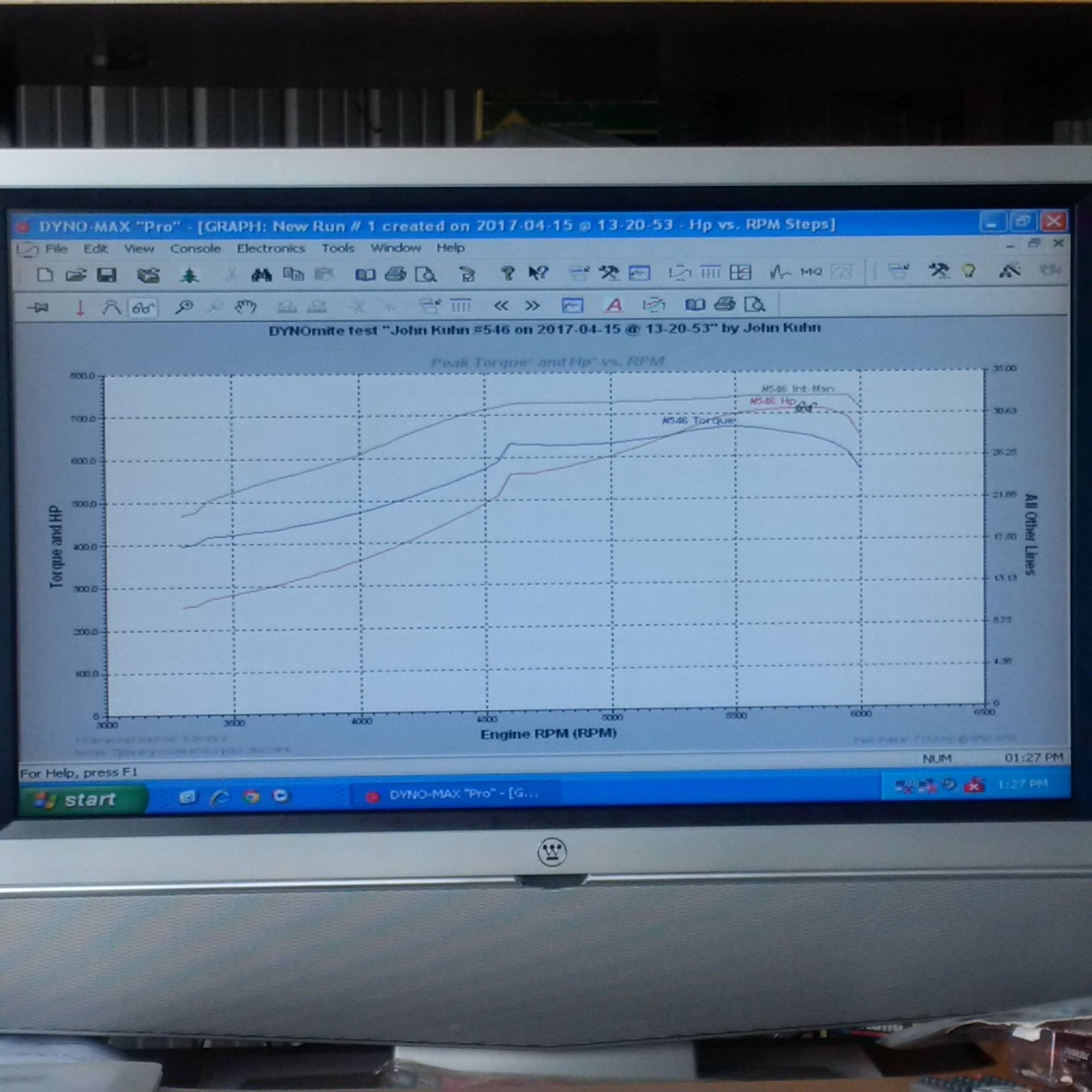
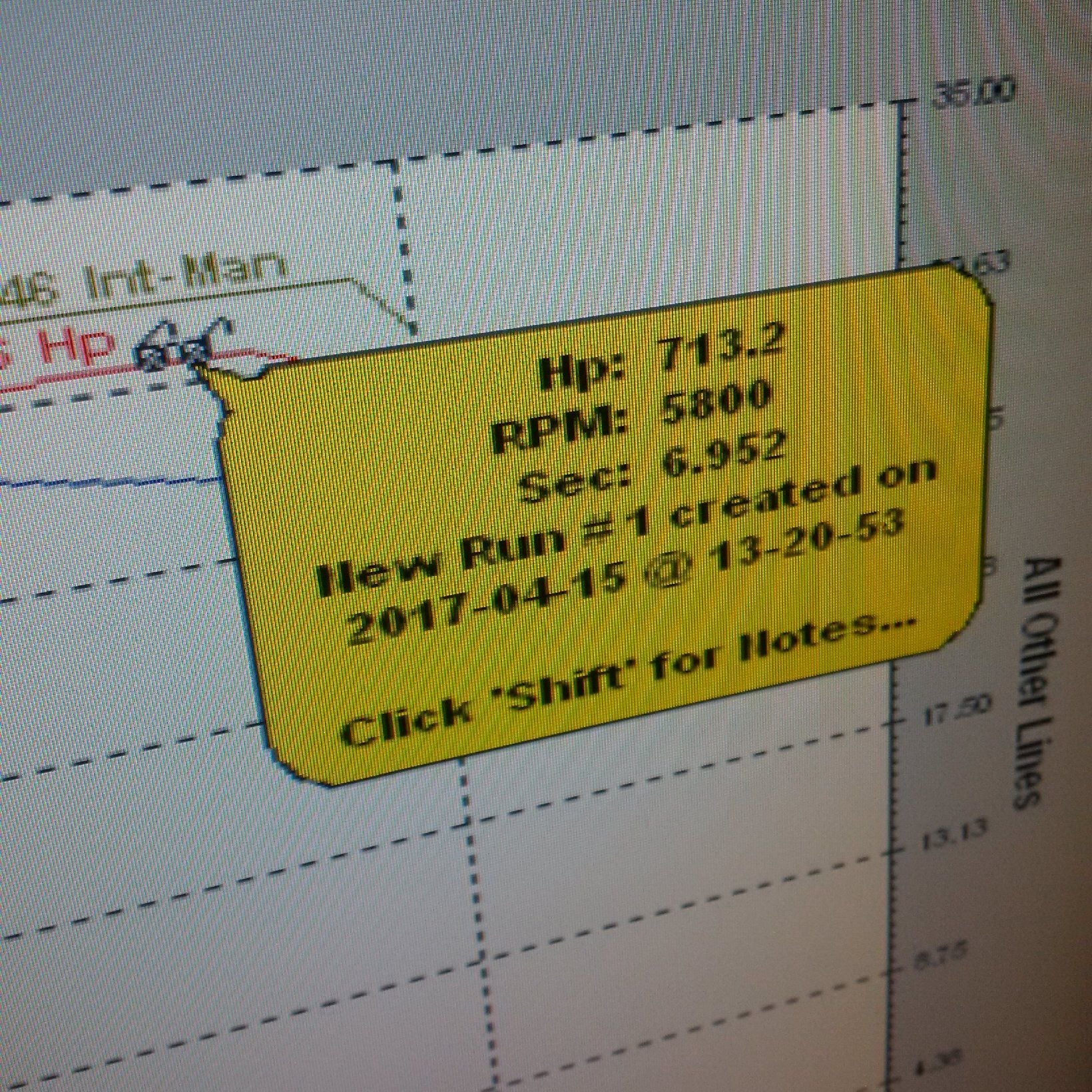
The car wants to make little over 700 rwhp on pump gas reasonably efficiently. Going past that on pump gas, we can foresee a number of issues. Dual 3" exhaust size, the LH and EZK consistency, intake manifold and throttle body, knocks especially at and above 6000 rpm, the heavy pistons and rods that can't go much above 6000 rpm anyway, etc. We'll work around those issues, but in my expectation we're pretty close to pump gas limit with 18 psi boost.
Intercoolers are still world beaters. 80 degrees in the shop, better than 80% effectiveness.
We also tested different ramp rates on the dyno. It's a turbo car, so one has to tune many different paths to full boost at 5000 rpm depending on the gear. Gear is being simulated by altering the dyno ramp rate.
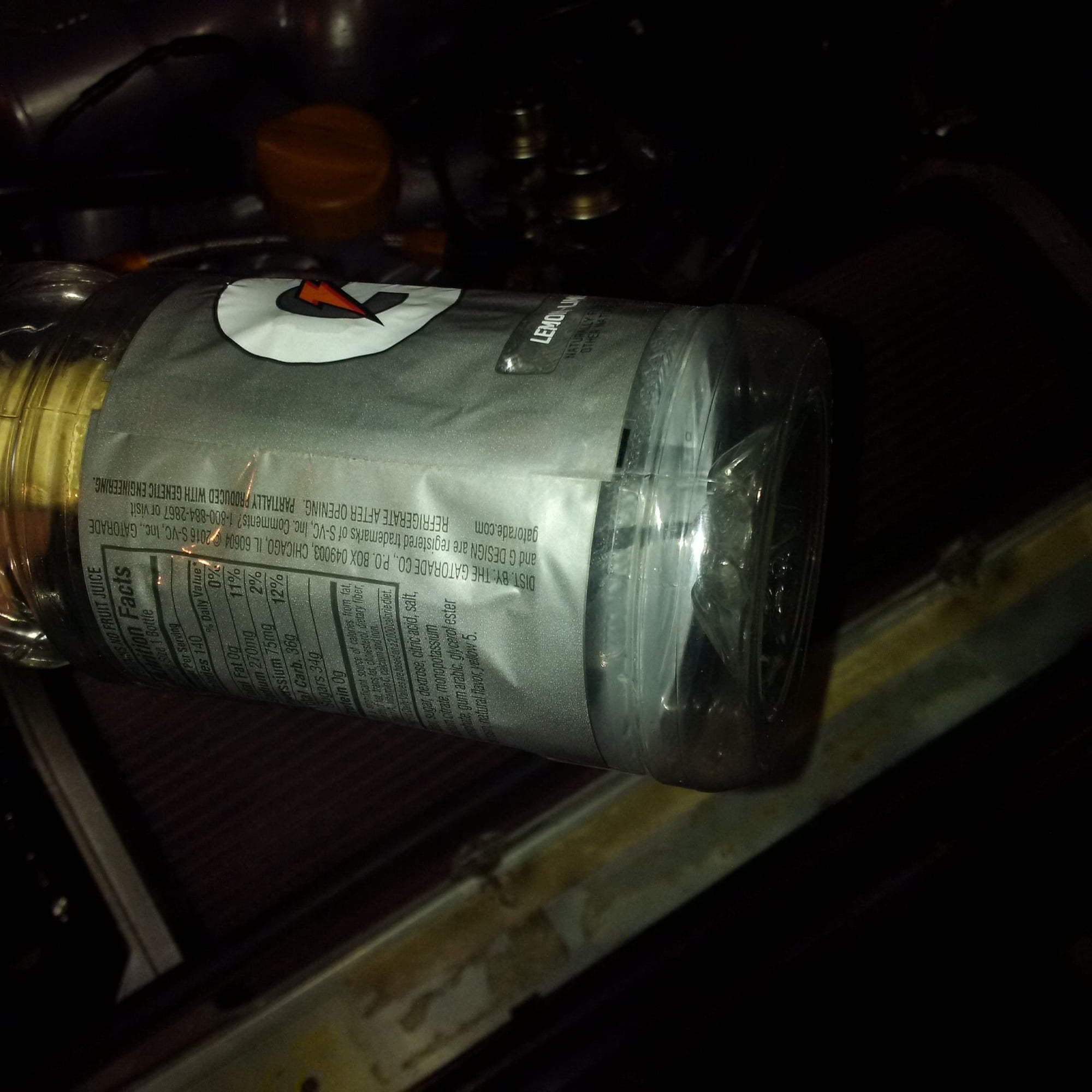
Catch cans have only water. I woudn't drink it, but it's pretty close to tap water in Flint MI.
are those wheel/hub numbers or "crank corrected"?
either way...holy ***t
Hub, with John's dyno. Only the density and temperature corrections applied. This was at barometric pressure of 14.5 psi and about 80 degree temperature in the shop.
When it's all said and done, we'll run the whole combo at an independent dynojet shop.
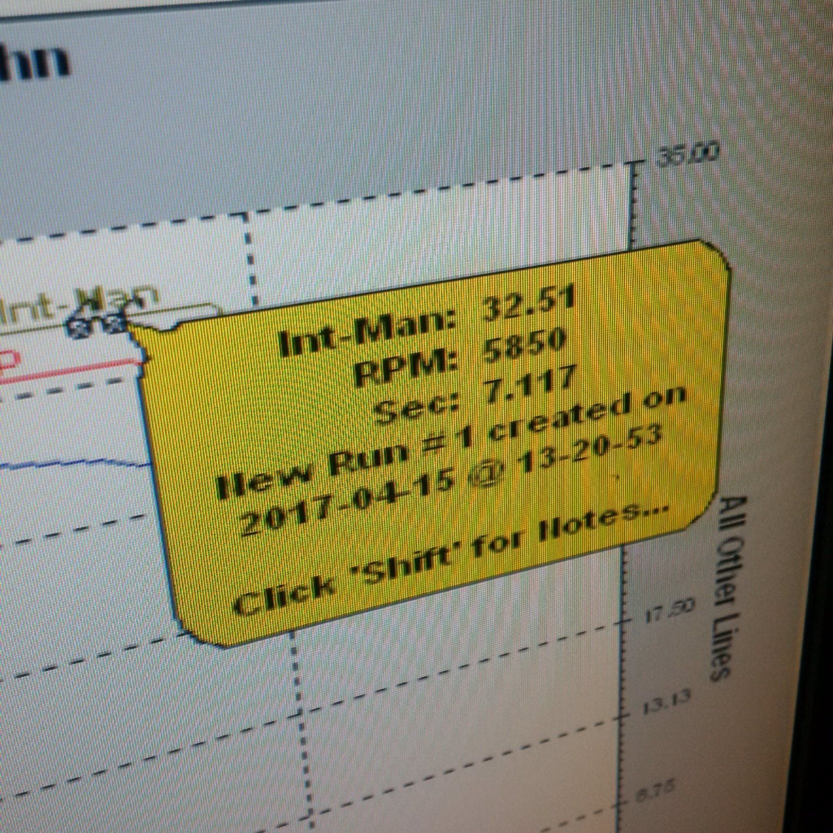
I take it the number on the right hand side of the chart is manifold absolute pressure [MAP] in PSIA? If so you are now at about 17 psig and pumping out 710 bhp [rwhp or bhp?].
I take it that that is cylinder No 6 leading the knock event charge -how many degrees retard at peak?
Those are very solid numbers- do you intend to dial back the timing a bit?
I take it the number on the right hand side of the chart is manifold absolute pressure [MAP] in PSIA? If so you are now at about 17 psig and pumping out 710 bhp [rwhp or bhp?]. I take it that that is cylinder No 6 leading the knock event charge -how many degrees retard at peak? Those are very solid numbers- do you intend to dial back the timing a bit?
That knock run was just to illustrate which are the knock-prone cylinders at each rpm. The pump gas tune that we'll actually run will be at close to factory-levelish knock probabilities.
With exhaust manifolds, turbo or stock, 1 and 6 are the most knock prone cylinders at 6000 rpm and above. With long tube headers, I'd expect this high rpm knock issue for those cylinders to be mitigated. Below 6000 rpm, cylinders with the best filling longer and straighter intake runners such as 2 and 6 are the most knock prone.
Yes, the pressure as are in absolute and hp at the rear axle. We're at about 32 or so psia in the intake and 35 in the exhaust. This thing wants a bigger exhaust than dual 3" which will bring the exhaust manifold back pressure close to boost.
That is not an exhaust it would be more like a horizontal industrial chimney!
Originally Posted by BC
Hence the reason when its acceptable, the turbo guys simply put a sewer pipe sticking out of the hood.
It's the conflicting requirements of very low downpipe back pressure and quiet sound when the load is low. the current exhaust works well for the pump gas runs, but it will not have the headroom for the race gas runs. So we have to figure out something there.
The intercoolers are breaking out on the upside. The pressure drop is very small considering how much heat they remove and to how close to ambient discharge measures.
The crankcase breather system also seems to be doing its job well, as are Kevin Johnson's deflector plates for the head oil drains.
Logically speaking, without piston squirters, it would seem to be a bad thing to keep the pistons from some or all of the oil spraying around from the crank. Obviously windage affects many things. But if you stop and think, keeping some of the oil off the crank throws (drainback control) is good- but keeping most of the oil off the crank (scraping) could be bad for piston tempature.

 04-10-2017, 09:27 AM