blown engine
 02-24-2016, 05:56 PM
#436
Former Vendor

Would some engines' IM shafts and bearings be installed misaligned at the factory by any chance ... due to minute manufacturing imperfections?
About 2 months ago the most eye opening case yet popped up.. A shaft that had a bearing failing, and was retrofitted with a competitors part. That part started to fail, so the bearing was blamed and the person bought a Classic Single Row LN bearing (even though he was advised not to, because the bearing previously had failed). That bearing was installed and within 6 months the engine had a similar noise reappear for a 3rd time. It was pulled apart, and the story started to get really interesting.
 02-24-2016, 05:58 PM
#437
Race Director
My favorite was the test rig that used (as I recall, my memory may be flawed) a shop vac and some matches to indicate the degree to which the intake...um...sucked.
*edit* Sorry, it was foamy discs, not matches. Told you my memory sucked.
*edit* Sorry, it was foamy discs, not matches. Told you my memory sucked.
02-24-2016, 06:04 PM
#438
Former Vendor
That video is revealing, until one realizes that the long side of that splitter does nothing on an NA engine, and the relevance of that test would only come into play when boost is involved... Thats never mentioned, though.
Dude obviously never spent any time on a flow bench, if he did, he'd know that the short side of the plenum/ port or etc is the only side that sees velocity in an NA application. On the long side, a pitot tube can be employed, and even at 28" IWC you won't see any velocity there thats measurable.
The way that unit builds "torque" is by reducing plenum cross sectional volume, which hurts HP, while making just a tad more torque over a very narrow range.
02-24-2016, 06:31 PM
#439
Racer
There's a lot more to the story. We have been gathering data to support this for years, measuring every shaft we can, and logging dimensions.
About 2 months ago the most eye opening case yet popped up.. A shaft that had a bearing failing, and was retrofitted with a competitors part. That part started to fail, so the bearing was blamed and the person bought a Classic Single Row LN bearing (even though he was advised not to, because the bearing previously had failed). That bearing was installed and within 6 months the engine had a similar noise reappear for a 3rd time. It was pulled apart, and the story started to get really interesting.
About 2 months ago the most eye opening case yet popped up.. A shaft that had a bearing failing, and was retrofitted with a competitors part. That part started to fail, so the bearing was blamed and the person bought a Classic Single Row LN bearing (even though he was advised not to, because the bearing previously had failed). That bearing was installed and within 6 months the engine had a similar noise reappear for a 3rd time. It was pulled apart, and the story started to get really interesting.
I hope some day we'll hear the end of that story ... but until then, I will respect your proprietary silence.
Cheers!
Martin
02-24-2016, 07:11 PM
#440
Drifting

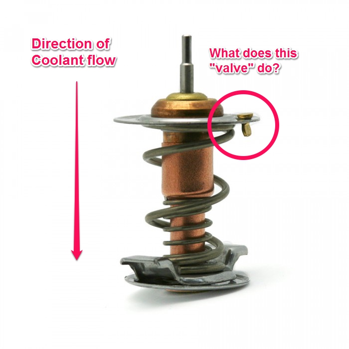
"An open IMS bearing only requires 1cc of oil per minute, you can spin the shaft 20,000 RPM and let it sling oil to Mars, and it'll still retain 1cc of oil per minute."
I am interested in that critical 1 cc of oil.
I am guessing that is just an estimate to emphasize how little oil is required to maintain a contiguous film of oil on the load bearing surfaces of the bearing? So most of that 1cc/min of oil would be filling the voids in a deep groove ball bearing & acting as a reservoir ?
If this is correct(???) the volume of oil actually providing the working film between the loaded ***** and race may be even smaller than the notional 1cc/min ?
Just trying to understand this issue.Apologies if I am way off base.
 03-01-2016, 03:22 PM
#442
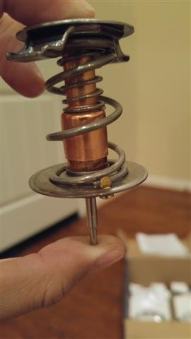
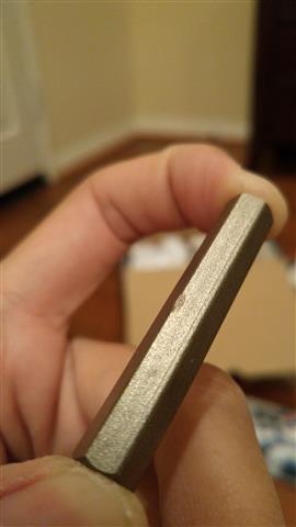
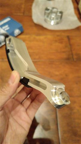
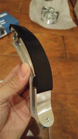
3/4" electrical conduit, compression union, and a 15mm deep socket... voila you got a tool 
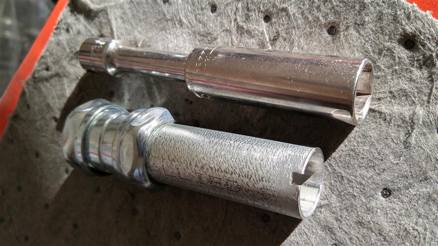
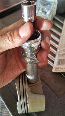
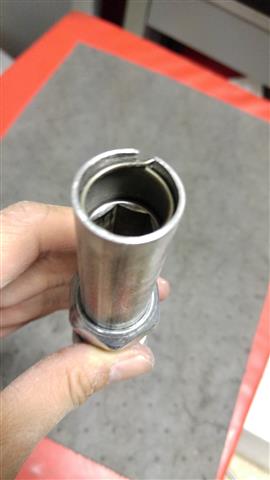
It's just for fun as I'm gonna get the Porsche timing/wrist pin clip tool (cloned) anyway.
It's just for fun as I'm gonna get the Porsche timing/wrist pin clip tool (cloned) anyway.
 03-01-2016, 04:10 PM
#444
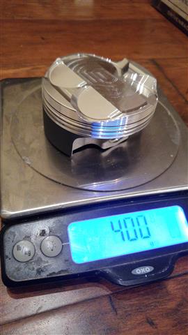
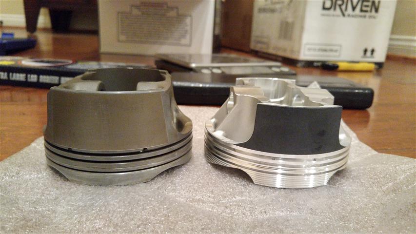
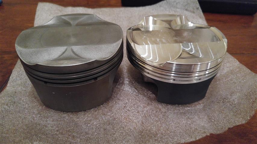
Thanks. More thoughts on the JE piston.
The pistons feel very solid with all the trusses (lightened) at the bottom.
The top edge of the piston has ribs supposed to reduce friction. That's interesting because I thought with the rings in place, the top of the piston should never touch the cylinder wall?
The coated skirt is shorter and has a much smaller contact area than the stock piston. I also found that not intuitive as you would think longer skirt should provide better stability, especially with the large thrust angle of the rods (short stroke).