When you click on links to various merchants on this site and make a purchase, this can result in this site earning a commission. Affiliate programs and affiliations include, but are not limited to, the eBay Partner Network.
Have you got a template you can post that I can cut out from?
I've still got the original aluminium templates I made but I'm not sure how I could capture these in an electronic format tho whilst maintaining scale. They're also 3D parts, so the ali template needs to be shaped. Most of the curves and bends are very slight so can be done with just your hands (1.2mm ali), but there are two 15cm long edges on both liners that require a compound curve. You can form this with a small ball hammer and a sandbag.
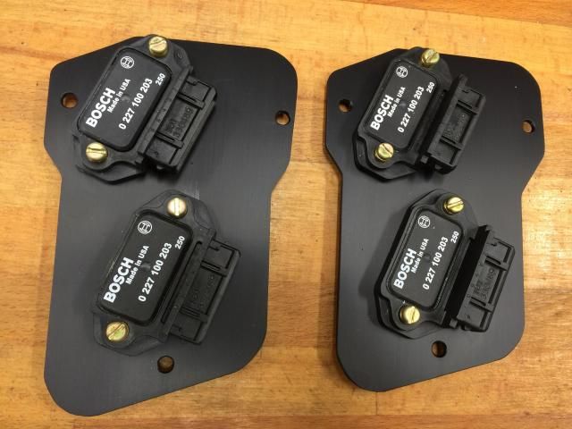
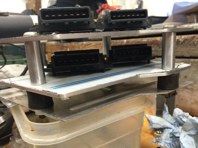
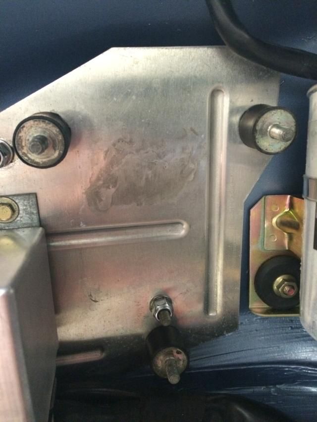
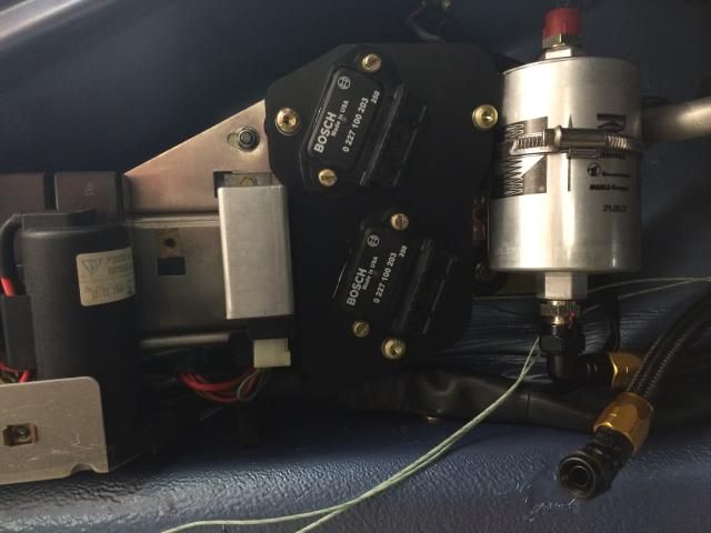
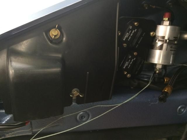
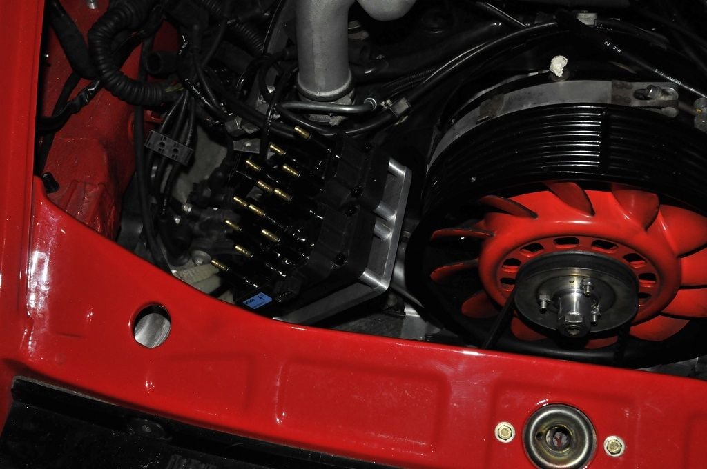
Here you go Rob, this is what I've done with the ignition components for my build; I no longer needed the EZ69 ignition module that mounts to the inner wing fuse/relay board, so re-used that space for making up some plates to mount the 4 x Bosch ignition amps to (bigger = better for heat sinking). They're then stacked with 3x spacers, using the rubber bobbins to try and isolate as much vibration as possible. I'm not familiar with the NA engine bay, but is this any use to you for when you remove the dizzies? --->
Thanks Spenny, thats good info and a nice neat setup. So you've opted to use four of the 3 channel 0 227 100 203 drivers. I assume therefore you're driving a coil per plug? I'll only need 2 of these with my coil packs.
What ECU are you using? Are you able to drive these modules directly? Can you configure the ECU ignition channels for both TTL or open collector?
Yup, I've dual plugged the heads (don't forget, the Turbo's only ran a single plug/cylinder), with each ignition module driving either the top or bottom bank of 3, for either 1,2,3 or 4,5,6...so, if a whole module did fail, I've still got a spark to each cylinder.
I'm using an MBE 9A9 ECU (you've seen my thread over on Pelican Parts, haven't you?). It's being mapped by my pal Steve @ SB Developments in Surrey, with the wiring by Simon @ Sileck down the road from me in New Romney.
The MBE does have built in amplifiers, but not 12 (8, if i remember correctly)....so if it were staying as a single plugged engine, then I could drive the Denso CoP's directly, but in order to drive 12 I needed to hand over ignition amp duties to the Bosch units, which in turn needed a custom version of the 9A9 making for me by MBE.
Here's a test that Simon and I setup a few months ago, to see just how powerful these bad boys are....(probably could've gone a few mm extra). It should ignite whatever's in the combustion chamber, eh?
W.r.t. TTL or open collector, I guess that's the low side drive vs high side drive outputs? In which case, no, mine is a custom board done at the HW level.
>(you've seen my thread over on Pelican Parts, haven't you?)
Eeek no I haven't - so thats tonights reading sorted and looking forward to it
Haha, it's a looong read, put the coffee pot on!....very much along the lines of your thread, also going into minute detail. I've noticed with yours, there so many people that get benefit from seeing various nuances on how you addressed this/that/the other (like our PM's re the fuel lines), if folk can benefit from seeing how I've gone about doing stuff, then great - how a community should work, imo. Conversely, the threads that show a beginning of a project, then 6mths and a dozen cheques later show the final result with nothing in-between....grr.
Absolutely, I actually enjoy documenting it also. It helps me too so that even I can remember how I did something when asked or if I have to go back to it
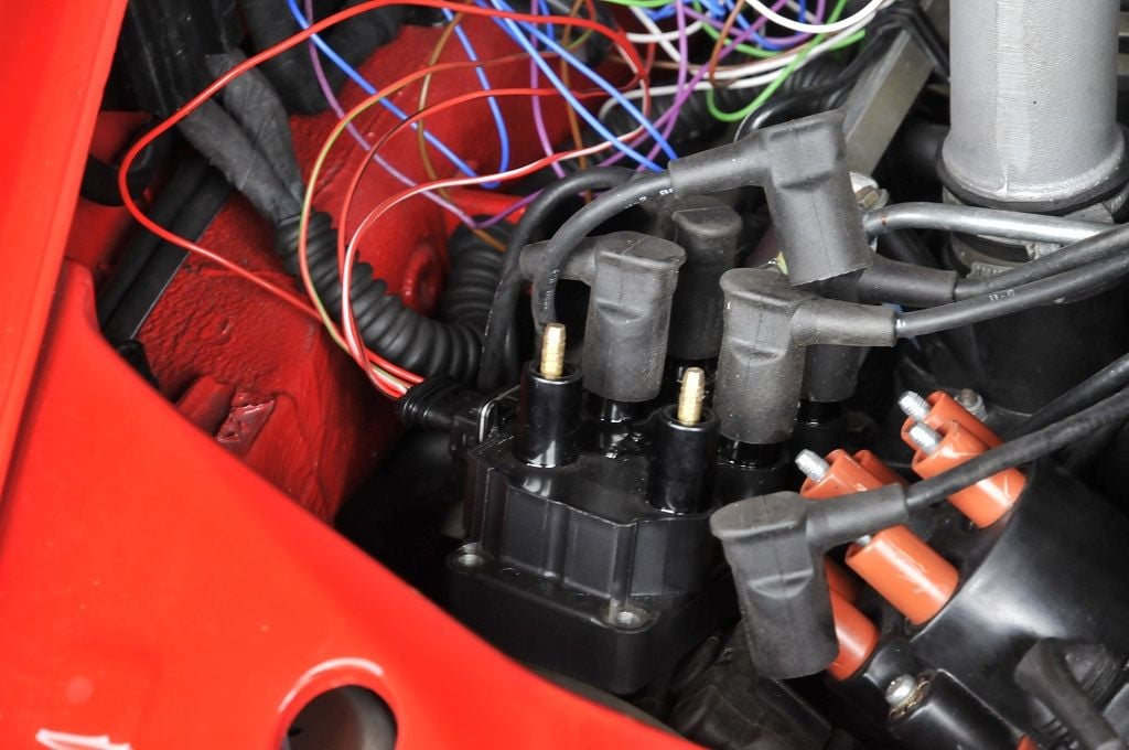
This weekends update. Before embarking on the removal of the stock coils, ignition modules, distributors and associated wiring, I wanted to test out the wasted spark setup. First of all I had to machine up the brass adapters that are needed so that the Porsche HT leads can connect to the Bosch coil packs. These proved quite simple to make and are pressed (light tapping with a hammer to push them home) into the coil packs leaving a nipple exposed in the same way you have on a distributor cap.
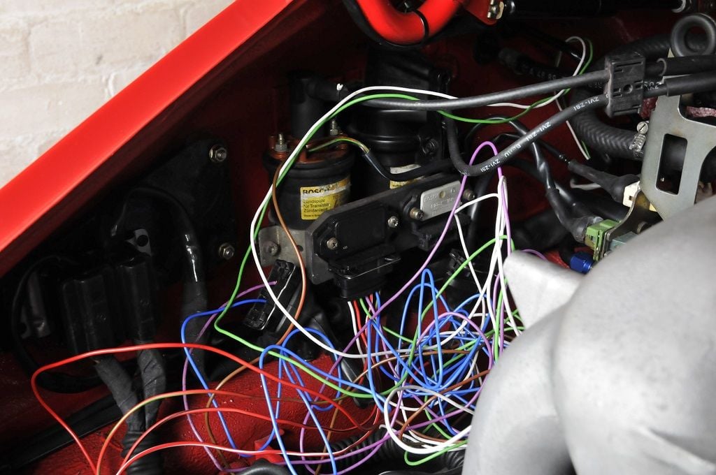
For this simple test I was only going to rig up the engine to run on the lower spark plugs. Removed one of the existing single channel ignition modules and replaced it with one of the new 3 channel ones. I then just wired it all up and reconfigured the ECU to drive it. Sorry about the birds nest wiring This is just a test - It obviously won't look like this later.
This is awesome. I just read up on Wikipedia and have some questions.
Where does the spark get its timing signal from?
And the way you're testing it, it is functioning as a true wasted spark setup, however, once you get all the ignition hooked up, will it still be a wasted spark?
Excellent! ECP came through and got some, or did you get them somewhere else in the end?
Notice any difference when you fired it up using the new amps? Guess it's difficult to tell until it's under load.
Hi Spenny, thanks for your help on that. Yep ECP sourced them. I've gotta now turn it all into something as factory looking as yours
Originally Posted by Vandit
This is awesome. I just read up on Wikipedia and have some questions.
Where does the spark get its timing signal from?
And the way you're testing it, it is functioning as a true wasted spark setup, however, once you get all the ignition hooked up, will it still be a wasted spark?
Ok lets break this down. First off there are two parts to this. There is timing and there is sequencing. Timing is still controlled by the ECU in exactly the same way as it was when using the distributor. All the distributor is doing is routing/sequencing the spark to the correct cylinder. The timing is driven by the ECU using the crank position sensor.
We're all familiar with the firing order 1-6-2-4-3-5. The engine will need to rotate 2 complete revolutions for all pistons to fire so can see that a piston reaches TDC every 120degrees. So when piston 1 is at TDC, piston 4 will be also. The difference is piston 1 is starting the power stroke whilst piston 4 is 360 degrees out of phase and finishing it's exhaust stroke.
This allows the pistons to be placed in 3 groups for firing as:
Group 1 1-4
Group 2 6-3
Group 3 2-5
For the wasted spark setup, you don't have to care which of the cylinders in a group is about to start the power stroke, you just fire them all. The spark is therefore 'wasted' on the piston thats on its exhaust stroke.
The ECU always knows exactly where it is from the crank position sensor. Instead of having a single ignition channel, we now have 3, one for each group. At the moment a cylinder needs to be fired, the ECU triggers the correct group based on the rotational position of the crank ie first 3rd (120degs), second 3rd (240degs), third 3rd (360degrees).
The test I've setup is a true wasted spark setup but only demonstrated using the lower spark plugs. An additional second coil park will be used for the top plugs and wired in identically. This will still be a wasted spark setup as the cyclinder firing / grouping will be the same.
Hi Spenny, thanks for your help on that. Yep ECP sourced them. I've gotta now turn it all into something as factory looking as yours
Ok lets break this down. First off there are two parts to this. There is timing and there is sequencing. Timing is still controlled by the ECU in exactly the same way as it was when using the distributor. All the distributor is doing is routing/sequencing the spark to the correct cylinder. The timing is driven by the ECU using the crank position sensor.
We're all familiar with the firing order 1-6-2-4-3-5. The engine will need to rotate 2 complete revolutions for all pistons to fire so can see that a piston reaches TDC every 120degrees. So when piston 1 is at TDC, piston 4 will be also. The difference is piston 1 is starting the power stroke whilst piston 4 is 360 degrees out of phase and finishing it's exhaust stroke.
This allows the pistons to be placed in 3 groups for firing as:
Group 1 1-4
Group 2 6-3
Group 3 2-5
For the wasted spark setup, you don't have to care which of the cylinders in a group is about to start the power stroke, you just fire them all. The spark is therefore 'wasted' on the piston thats on its exhaust stroke.
The ECU always knows exactly where it is from the crank position sensor. Instead of having a single ignition channel, we now have 3, one for each group. At the moment a cylinder needs to be fired, the ECU triggers the correct group based on the rotational position of the crank ie first 3rd (120degs), second 3rd (240degs), third 3rd (360degrees).
The test I've setup is a true wasted spark setup but only demonstrated using the lower spark plugs. An additional second coil park will be used for the top plugs and wired in identically. This will still be a wasted spark setup as the cyclinder firing / grouping will be the same.
Rob, thanks for the great "wasted spark" primer. Your description is so clear that even I understood what you're talking about!
So the way it is running in test is firing 2 plugs at a time, and once fully hooked up it'll fire 4 plugs at a time. Both wasted spark.
Yes, the test is using only 1 plug per cylinder. The Bosch coil pack is designed for 6 cylinder engines, running wasted spark with 1 plug per cylinder. We have 2 plugs per cylinder so must run 2 coil packs.
It can't be hooked up to fire 2 at a time (on the same cylinder)? 6 pairs of firings versus 3 quads of firing?
It could if different (12)coil packs were used and 6 ignition channels instead of 3, but it would no longer be a wasted spark configuration.
With wasted spark coils, you should not run both HT terminals of the same coil winding to the same cylinder in twin spark systems. You will end up with a weaker overall spark. It must be configured so that when it fires, only one of the cylinders is under compression.
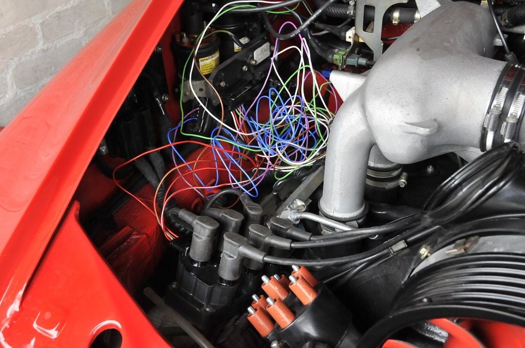
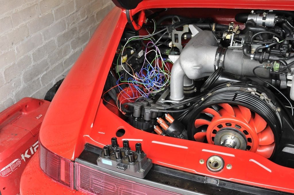
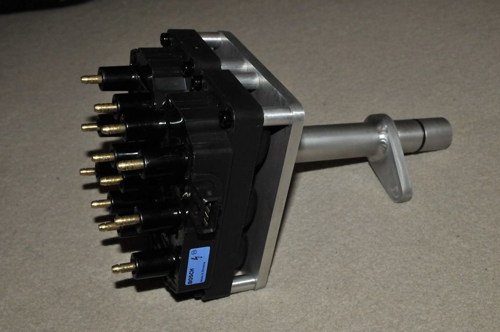
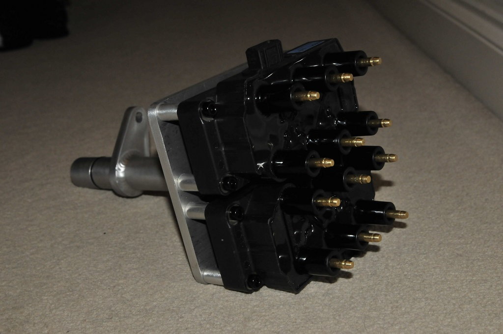
Time to update this thread I think! Progress has been painfully slow of late but but I've finally got something to show for it. I've been scratching about for a while trying different methods and positions of mounting the coil packs but only one arrangement really worked best so here it is.
It looks a little funky but positions the coil-packs similar to that of the original dizzy caps allowing me to keep the existing HT leads. The end of the mount (with the arm) is identical to that of the distributor and so drops into the crankcase and fastens in the same manner. There is also an o-ring on the shaft to ensure an oil tight seal.
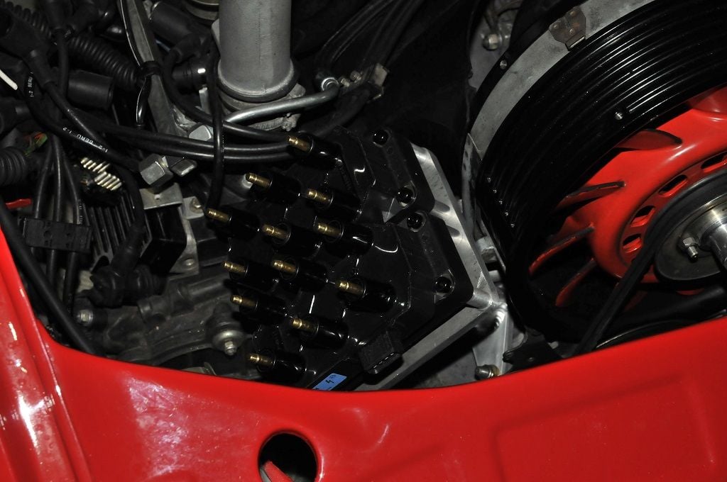
And here it is in position.
Sorry about the dark images. It was ummmm dark outside

 12-29-2014, 05:54 AM