
964 Refurb
 02-23-2015, 11:16 AM
#856
Race Car
nice work Rob .. haven't seem a 964 loom out the car but I can imagine its a heck of alot more than your new one ... and at least a few kilo's heavier!
I like the super thick backing plate for the TPS ... but isn't it too thick for the length of the rod that comes thru the throttle body from the throttle cable side? Have you tried to fit it yet? Is it a bosch TPS or does it have a VAG number?
(ps - I have a much thinner mounting plate and I thought it was the source of some noise in the TPS signal .... as I mentioned in my dev journal it was actually a messy 5V power source to the TPS from the motronic though. pps - Mine is an MY90 though.)
 02-23-2015, 11:53 AM
#857
Three Wheelin'
Thread Starter
The same has occured to the wires on the ends of the engine sensor plugs. Pull back the rubber hoods on the connectors and I bet you see bare copper in places where the insulation is splitting and breaking down. I wince each time I need to unplug the two big engine loom connectors. Its as if they're made of bakelite. My replacement looms will use all new connectors, modern thin wall conductors and heatproof sleeving. Modern vehicle wiring is capable of carrying much larger currents than the older stuff for a give swg. This makes the looms much smaller, lighter and manageable.
Specialist Components did say it'll fit right on but you might be right. I haven't even offered it up to the engine to eye-ball yet. I'll check for partnos.
03-02-2015, 04:11 AM
#858
Three Wheelin'
Thread Starter

This TPS is just like any other I've seen in terms of the drive spindle it needs. It's the Porsche end thats weird. Not sure how your's is coupled Hiwind but I've not seen a TPS with a spindle as small as the porsche throttle spindle.
Wired in, configured and cranked it up - all good. The next job to look at is the cam phase hall sensor. I was going to leave this a while but watching the wideband lambda reading running on closed loop, I can see its adjusting fuel by 6% on idle (too rich) and varying degrees at other positions. It didn't do this before. This will be down to the engine being forced to run batched injection when the original map is for sequential. So, there is no point me getting the car on the rollers yet for a mapping tweak until the cam phase sensor is sorted or I'll have to do it again afterwards as well. I didn't expect it would effect the fueling so much.
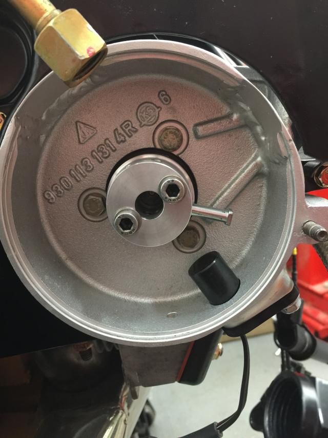
Since I have no engine driven PSP, I'll drive the cam phase off the end of that cam. Annoyingly, the exhuast bracket is mounted stand-off accross that area of the head making clearence tight. I've got about 5cm of depth to play with. I removed the rothsport cam end cover and a teaspoon of oil rolled out. As the cam end has no oil seal, I'll guess it will need one.
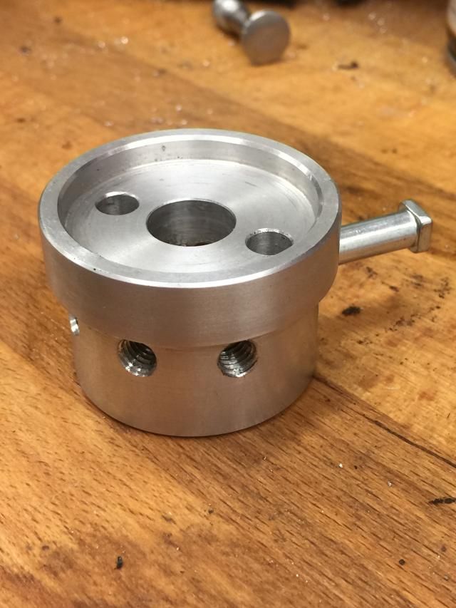
To save machining time I took the old PSP backing plate that has one built in, cut it out with a grinder and then cleaned it up on the lathe. It's perfect. It's now a 70mm disk complete with the correct positioned mounting holes and recess for the oil seal. But then it would be, since that was it's original place and job
I now need to take a 50mm long section of 70mm round ally bar and turn up the top half of the housing to take the sensor. I'll add some pictures later to make this easier to follow The 37way Deutch motorsport connectors arrived on Saturday so I can also get started on the new ECU / Engine loom. I'm loving the clean uncluttered look of the engine bay right now.
03-02-2015, 02:47 PM
#859
Race Car
spindle - that's the word! Yes I figured it would be too thick
... my TPS is a VAG (bosch) part which looks very similar to yours though - any identifying numbers or moulding?
My spindle is half round and the female side of the TPS suited that, but was a bit lose so I added a bit of hard rubber inside to snug it up. Signal is good and allowed for ~99% of the spindle movement and tested it a few times with the software which allows calibration and it didn't lose/change range after a few days so I think its good.
The rest of what you said sounds cool ... but I coudlnt follow it all need pics!
... my TPS is a VAG (bosch) part which looks very similar to yours though - any identifying numbers or moulding?
My spindle is half round and the female side of the TPS suited that, but was a bit lose so I added a bit of hard rubber inside to snug it up. Signal is good and allowed for ~99% of the spindle movement and tested it a few times with the software which allows calibration and it didn't lose/change range after a few days so I think its good.
The rest of what you said sounds cool ... but I coudlnt follow it all
need pics!
03-03-2015, 04:48 AM
#860
Three Wheelin'
Thread Starter
Nadda - Only ID is the number on the box in which it arrived in.
Spent 3 hours lastnight staring and measuring the hall sender, end of the cam and the oil seal housing waiting fo the eureka moment on the best way of doing this
Ordered the indexable cutting inserts and a new boring bar so I can get going once I've worked it out.
Spent 3 hours lastnight staring and measuring the hall sender, end of the cam and the oil seal housing waiting fo the eureka moment on the best way of doing this
Ordered the indexable cutting inserts and a new boring bar so I can get going once I've worked it out.
03-03-2015, 04:56 AM
#861
Three Wheelin'
I will say though that I'm not sure your symptoms are due to the lack of cam synch. There are plenty of closed loop lambda bank/batch injection cars in the world, sure its not as precise esp with really big injectors but a big trim like that seems more related to a slightly out of whack VE table in my mind, or maybe even injector characterisation.
03-03-2015, 06:29 AM
#862
Three Wheelin'
Thread Starter
It could be, butI'm certain there was no appreciable delta prior to me switching the cam phase off. Unlike the motronic, the TYPH2 won't automatically switch to batch mode on loss of cam synch. It's a config change and the engine won't run if it expects one and doesn't get it. Sure there are plenty of batch config'd engines about but would they have not have been mapped with that config from the get-go? I'm guessing...
03-03-2015, 06:45 AM
#863
Three Wheelin'
It could be, butI'm certain there was no appreciable delta prior to me switching the cam phase off. Unlike the motronic, the TYPH2 won't automatically switch to batch mode on loss of cam synch. It's a config change and the engine won't run if it expects one and doesn't get it. Sure there are plenty of batch config'd engines about but would they have not have been mapped with that config from the get-go? I'm guessing...
I forgot you ran with the dizzys at first, so if there was no trim back then as you say the VE must have been close.
I'd look at injector characterization, if the dead time is set too short in the ecu then the when you double it up by running batch you would see a more noticable effect. And you wouldn't notice at full chat as the dead time is inconsequential at bigger injector duty but at idle where say you have 10ms pulses then a 250us mis-calibration will make a difference especially if you then split it to run two 5ms pulses and get two dead times added to the total pulse. Are they EV1,EV6 or EV14 injectors?
Doesn't really matter though, cam synch is cool, and you'll make it work
 They're 440cc fuel injectors - Bosch 0 280 156 280
03-03-2015, 07:31 AM
They're 440cc fuel injectors - Bosch 0 280 156 280
03-03-2015, 07:31 AM
#865
Three Wheelin'
Anyway with 440s (effectively bigger because they are 440 at 3bar and the rail pressure is higher than that) you will have fairly short pulses in batch mode. When you run down to really short pulses it can be very difficult to model the injectors' behaviour and the normal voltage offset table doesn't really cut it and you may only get full success going back to sequential. I have spent many hours pulling my hair out on this.
Does the typhon give you a log of the injector duty?
03-03-2015, 07:52 AM
#867
Three Wheelin'
As a point of reference I've seen a 6% trim induced as a result of changing something as small an induction kit in the past.
03-03-2015, 08:06 AM
#868
Rennlist Member

Join Date: Jul 2005
Location: Kent, UK
Posts: 156
Likes: 0
Received 0 Likes
on
0 Posts
Hey Rob,
I had to re-do my cam timing sender the other week - for some inexplicable reason, the sender was right over the sensor @TDC...the only place you really don't want it, as it's an indeterminate state w.r.t. which cycle it's on. Re-made the whole spindle and a new sender. We can now just plug in the X� offset to sync it with the crank position. Have a look at the last few pages of the thread, you'll see what I mean.
If you ever get problems with stock TPS (they're not the most reliable of things), then look into Penny & Giles units.... Steve @ SBD sells them.
I had to re-do my cam timing sender the other week - for some inexplicable reason, the sender was right over the sensor @TDC...the only place you really don't want it, as it's an indeterminate state w.r.t. which cycle it's on. Re-made the whole spindle and a new sender. We can now just plug in the X� offset to sync it with the crank position. Have a look at the last few pages of the thread, you'll see what I mean.
If you ever get problems with stock TPS (they're not the most reliable of things), then look into Penny & Giles units....
Steve @ SBD sells them.
03-03-2015, 08:09 AM
#869
Three Wheelin'
Thread Starter
Whilst I have your attention I have a question for you
Do you happen to know where in relation to the cycle the ECU expecting to see the cam phase signal? I know I can work it out by realigning the standard dizzy and measuring it but if you happen to know.... ? Also, as it is purely used to indicate phase I assume its not too fussy on being either side of the correct point by a few degrees? I have a scope so can plot it against every 2nd revolution of the flywheel patten and use the reference point on that.
I have a question for you Do you happen to know where in relation to the cycle the ECU expecting to see the cam phase signal? I know I can work it out by realigning the standard dizzy and measuring it but if you happen to know.... ? Also, as it is purely used to indicate phase I assume its not too fussy on being either side of the correct point by a few degrees? I have a scope so can plot it against every 2nd revolution of the flywheel patten and use the reference point on that.
03-03-2015, 07:07 PM
#870
Rennlist Member
Join Date: Jul 2005
Location: Kent, UK
Posts: 156
Likes: 0
Received 0 Likes
on
0 Posts
Whilst I have your attention I have a question for you
Do you happen to know where in relation to the cycle the ECU expecting to see the cam phase signal? I know I can work it out by realigning the standard dizzy and measuring it but if you happen to know.... ? Also, as it is purely used to indicate phase I assume its not too fussy on being either side of the correct point by a few degrees? I have a scope so can plot it against every 2nd revolution of the flywheel patten and use the reference point on that.
I have a question for you Do you happen to know where in relation to the cycle the ECU expecting to see the cam phase signal? I know I can work it out by realigning the standard dizzy and measuring it but if you happen to know.... ? Also, as it is purely used to indicate phase I assume its not too fussy on being either side of the correct point by a few degrees? I have a scope so can plot it against every 2nd revolution of the flywheel patten and use the reference point on that.
But when I remade the boss, I drilled and tapped multiple M6 holes so that when we're up on the dyno, with time being very much of the essence, we can quickly remove it and relocate into another hole if required. Of course, I only needed half the amount of holes, as the boss itself can be switched 180�, but in my own little OCD mind, this looked neater (balanced)
Not sure if that's of any help, sorry!