When you click on links to various merchants on this site and make a purchase, this can result in this site earning a commission. Affiliate programs and affiliations include, but are not limited to, the eBay Partner Network.
:-) Y and F are the 2 points I'm looking for. Just for ease of measurement... Thanks for clarifying, though.
Is your driveshaft still coupled to your trans, I hope?
Thanks,
Alan
Thanks Alan! - Yes, still connected to the trans at the other end, and all still mounted in the car (except for the engine). Will get you some measurements tonight. this weekend
Measure from the underside of the crossmember, front edge, center of car.... up to a point on the underside of the hood that is about 6 inches forward of the front of the crossmember. If you have about 24.5" it should clear the valve cover with a little wiggle room. Intake manifold is lower and should not be an issue.
This of course assumes that the bottom of the 968 crossmember is in the same location as a 944. Also, I'm not sure if the 968 has hood insulation, but if so that would need to be removed in a small area.
To clarify, 6" forward of the front lower crossmember edge and then straight up? (not a diagonal from the edge to a spot 6" forward?)
For my 968:
Straight up at the crossmember I've got 24.75"
Straight up 6" forward of the crossmember I've got 24"
Both of these are to the center support beam with no insulation. Probably have an extra 3/8-1/2 if the highest point of the VC isn't at the inner support location.
It's been a while since I've looked up the process for TT installation, but is the idea that the shaft bottoms out on the pilot bearing?
I've got a torque tube out of the car that I could measure if that's any help. I could measure the max and min excursion. Measuring it with the trans attached is going to have a variance too I imagine since the adapter is just a splined compression fit.
I have been looking for the flow rate on the factory 07k injectors and for the life of me can`t find anything . I`ve tried all my usual searches , vwvortex , google , even checked a couple sites that rebuild injectors and nothing . I have found high flow injectors and stock replacements but nothing stating what the factory size is . Anybody able to shed some light on this ? P.S. I`m no help with the input shaft measurement either as my engine is still in the car and running decent for a 33 year old engine .
I have been looking for the flow rate on the factory 07k injectors and for the life of me can`t find anything. I`ve tried all my usual searches, vwvortex, google, even checked a couple sites that rebuild injectors and nothing. I have found high flow injectors and stock replacements but nothing stating what the factory size is. Anybody able to shed some light on this? P.S. I`m no help with the input shaft measurement either as my engine is still in the car and running decent for a 33 year old engine.
I wasn't able to find anything either... This may or may not be helpful, but a quick search gave me a process for how to measure them.
They're rated in units of cubic centimeters per minute. Take 1 injector, pressurize the line, apply 12+ volts, measure how much comes out in 1 minute. If you can figure out the PSI of the stock fuel rail, and a way to replicate it, you might be able to get a rough estimate.
But also just by plugging in 170 hp @ 5 injectors, 80% duty cycle, gave me ~200cc. https://www.deatschwerks.com/fuel-ca...tor-calculator
I think it's safe to guess it's a fairly low rate, knowing these cars were designed for fuel efficiency.
Last edited by senior_squishy; 01-19-2019 at 02:16 PM.
I know the 07k uses a returnless fuel system , like the LS engines do . I am pretty sure these are set at about 50psi at the rail and it does not change . I would say using the calculator you posted , 8 of the stock 07k injectors would feed another little project I am working on . Guess I need to get some graduated test tubes and start working on an injector test bench .
returnless is good for only so much power and is really an emissions fix...
for real power you'd want to convert to a return style, easy since the car's already plumbed for it
Your numbers seem very close to the 944 hood measurements to the center rib. The valve cover is offset from center, so I think you will be ok.
Alan
Originally Posted by alxdgr8
To clarify, 6" forward of the front lower crossmember edge and then straight up? (not a diagonal from the edge to a spot 6" forward?)
For my 968:
Straight up at the crossmember I've got 24.75"
Straight up 6" forward of the crossmember I've got 24"
Both of these are to the center support beam with no insulation. Probably have an extra 3/8-1/2 if the highest point of the VC isn't at the inner support location.
It's been a while since I've looked up the process for TT installation, but is the idea that the shaft bottoms out on the pilot bearing?
I've got a torque tube out of the car that I could measure if that's any help. I could measure the max and min excursion. Measuring it with the trans attached is going to have a variance too I imagine since the adapter is just a splined compression fit.
Yes, there will be some variability. I'm just trying to center my design on the range.
I think I will loosen the bolts that hold the coupler on my car, and slide the driveshaft all the way back and all the way forward (within the limits that the grooves in the shafts allow the coupler bolts to move).
As of yesterday, I have received all of the parts from iAbed, and obviously I already had my engine mount parts. So, I can ship everything very soon. This weekend, Mike Hinton and I will be taking pictures and making notes about the installation process, which will be shared with you all (perhaps on a Boost Brothers Garage youtube vid or written instructions on his web store). If all goes well, I hope to pack up the kits on Sunday, and ship them out early next week.
I do have some questions for you guys...
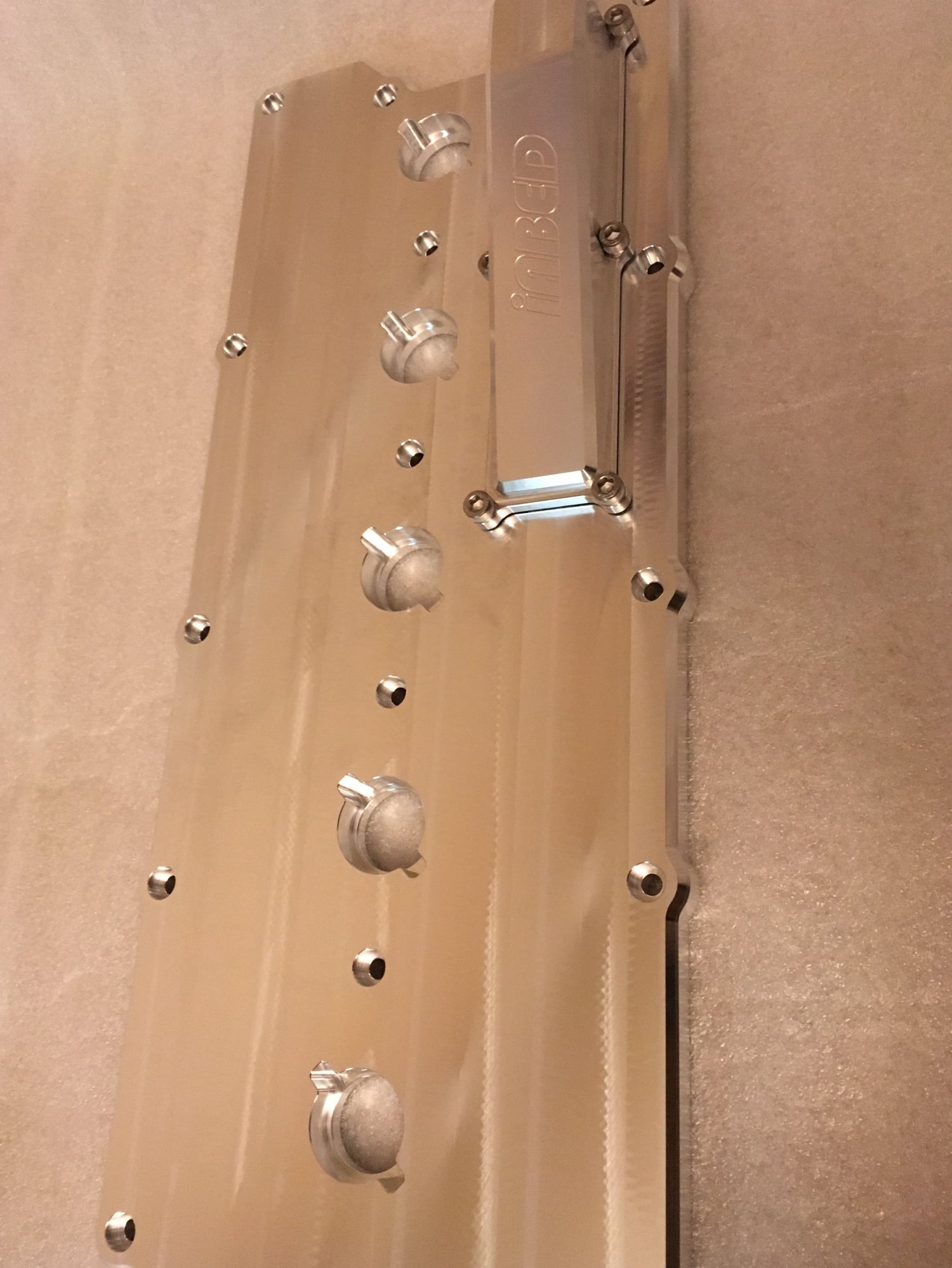
1. The valve covers were shipped to me without any seals. iAbed's thought was that we should silicone the valve cover to the head, with the assumption that we would not need to remove it in the future. For me personally, that is not the case, so I may try to find a gasket solution for my valve cover. I will probably try to find some silicone o-ring stock that will fit in the groove he machined around the perimeter. I will also try to find o-rings for the holes around the coils and bolts running down the center. If anyone is interested in these, let me know and I can ship them to you at a later time.
2. The breather boxes were shipped with an o-ring seal. I'm not convinced yet that this seal works perfectly, but worst case scenario is putting some silicone around it before tightening it to the valve cover. In my opinion, the breather box falls into the category of not needing to be removed from the valve cover once installed.
3. The breather boxes need some sort of steel wool or other media to catch heavy oil that is thrown up under the valve cover before going to your catch can or other PCV system. I do not have that media yet. I will be looking into the best media to use and can ship to you later if you're interested (perhaps for a small fee). If anyone has a good tip on the best media to use for this, let me know. Keep in mind that this breather box is not intended to be used in lieu of a catch can. So, this media might be different than what you would normally see inside a catch can?
returnless is good for only so much power and is really an emissions fix...
for real power you'd want to convert to a return style, easy since the car's already plumbed for it
oh I�m going to run a return system . I�m just trying to work out the flow . I can�t properly tune an engine if I don�t know the injector flow .
vt951 - plenty of OEM cars with "breather boxes" use a sort of labyrinth of hole-punched plates to filter out the heavier oil. no risk of coming apart like steel wool.
something to think about.
As of yesterday, I have received all of the parts from iAbed, and obviously I already had my engine mount parts. So, I can ship everything very soon. This weekend, Mike Hinton and I will be taking pictures and making notes about the installation process, which will be shared with you all (perhaps on a Boost Brothers Garage youtube vid or written instructions on his web store). If all goes well, I hope to pack up the kits on Sunday, and ship them out early next week.
I do have some questions for you guys...
1. The valve covers were shipped to me without any seals. iAbed's thought was that we should silicone the valve cover to the head, with the assumption that we would not need to remove it in the future. For me personally, that is not the case, so I may try to find a gasket solution for my valve cover. I will probably try to find some silicone o-ring stock that will fit in the groove he machined around the perimeter. I will also try to find o-rings for the holes around the coils and bolts running down the center. If anyone is interested in these, let me know and I can ship them to you at a later time.
2. The breather boxes were shipped with an o-ring seal. I'm not convinced yet that this seal works perfectly, but worst case scenario is putting some silicone around it before tightening it to the valve cover. In my opinion, the breather box falls into the category of not needing to be removed from the valve cover once installed.
3. The breather boxes need some sort of steel wool or other media to catch heavy oil that is thrown up under the valve cover before going to your catch can or other PCV system. I do not have that media yet. I will be looking into the best media to use and can ship to you later if you're interested (perhaps for a small fee). If anyone has a good tip on the best media to use for this, let me know. Keep in mind that this breather box is not intended to be used in lieu of a catch can. So, this media might be different than what you would normally see inside a catch can?
Wonder if the OE 07k valve cover gasket will work? p/n 07K103483B
On all of the newer TSI engines Audi/VW no longer use valve cover gaskets, they use a green anaerobic sealant, p/n D154103A1. I believe that's what Iroz has used on all of their engines with billet VC's. It's totally still removable, but it is expensive so it's not something you want to make a habit out of.
Issam should be able to recommend some stainless steel wool, he has used that in some block breathers he designed for older I5's.


 01-17-2019, 06:06 PM