When you click on links to various merchants on this site and make a purchase, this can result in this site earning a commission. Affiliate programs and affiliations include, but are not limited to, the eBay Partner Network.
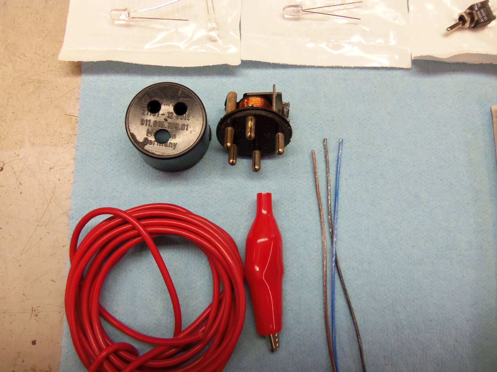
Because I like doing things the hard way, I bought a Werhle round case 911/914 relay. Disassembly went about as well as could be expected for me. In all my infinite wisdom, I decided to split the sealed seam at the back of the case by hand. On a bench grinder. Well...I didn't ruin the case, but it didn't come apart.
So...onto one of the smaller lathes at work. I chucked the case up in the lathe and set it to slow speed. I very carefully cut away at the seam until the case and back plane separated.
No photos of this, as I am not proud of what I did, and didn't have my camera with me that night.
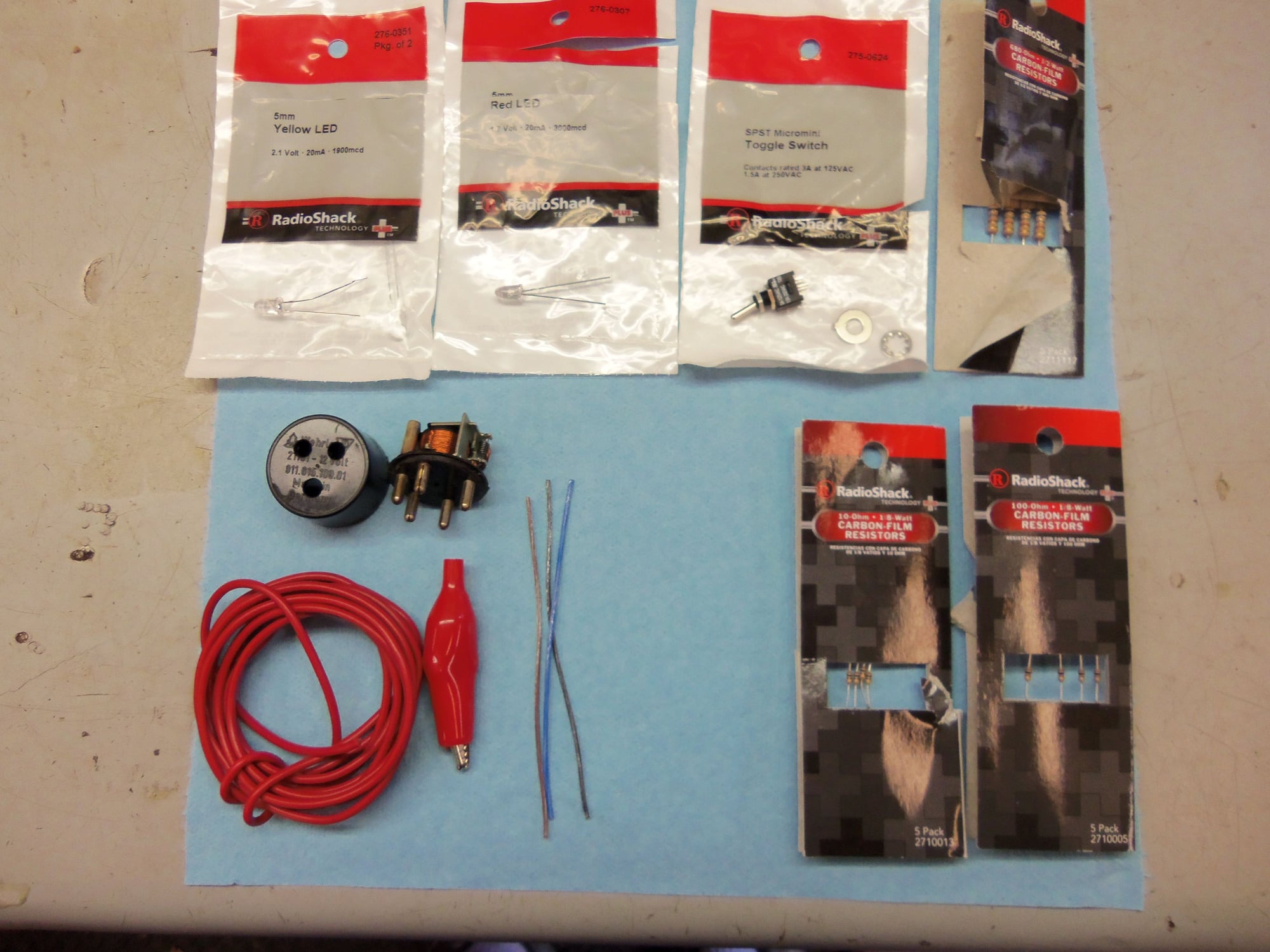
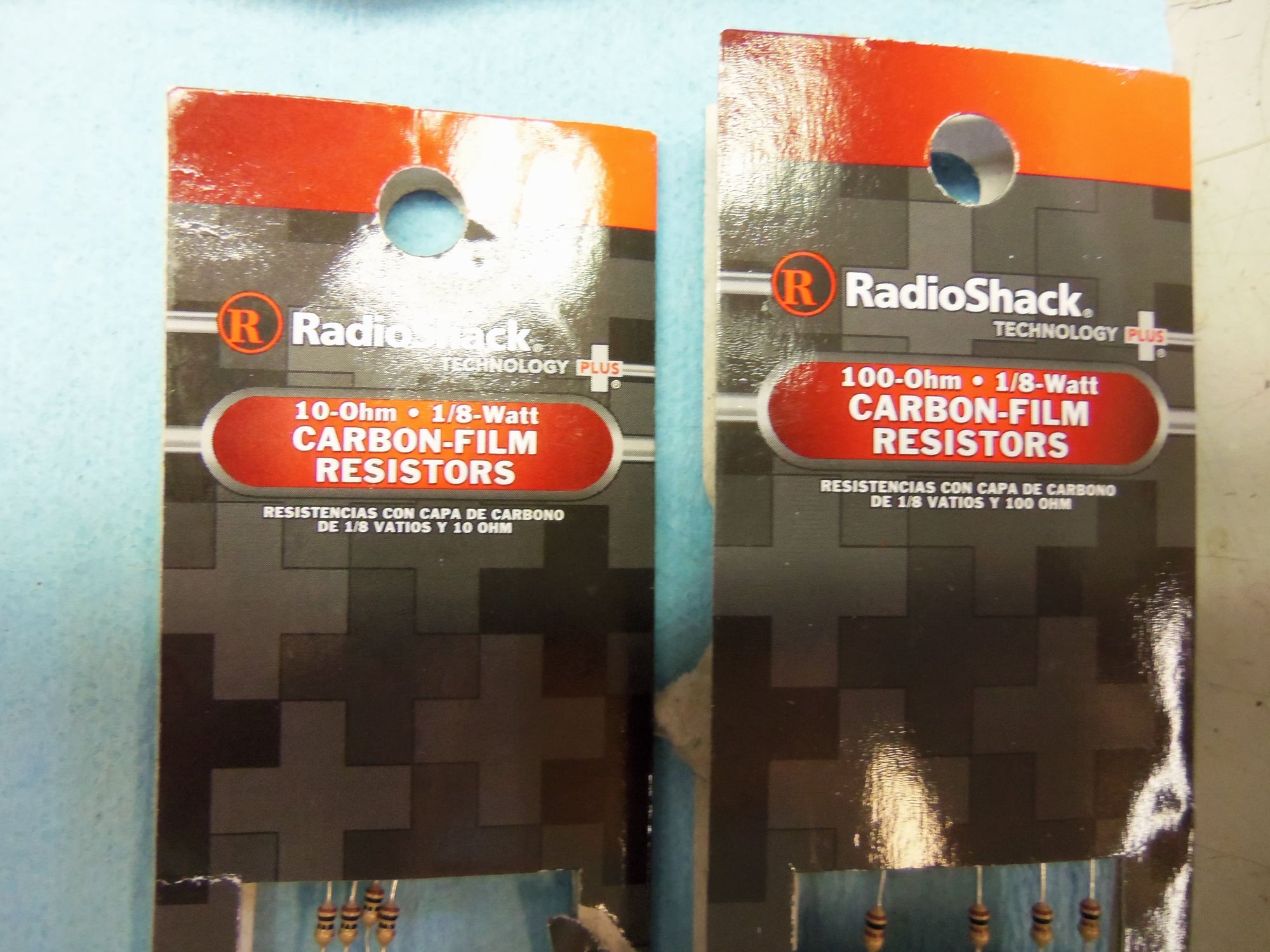
Unable to find suitable LED's at work, I went shopping at Radio Shack:
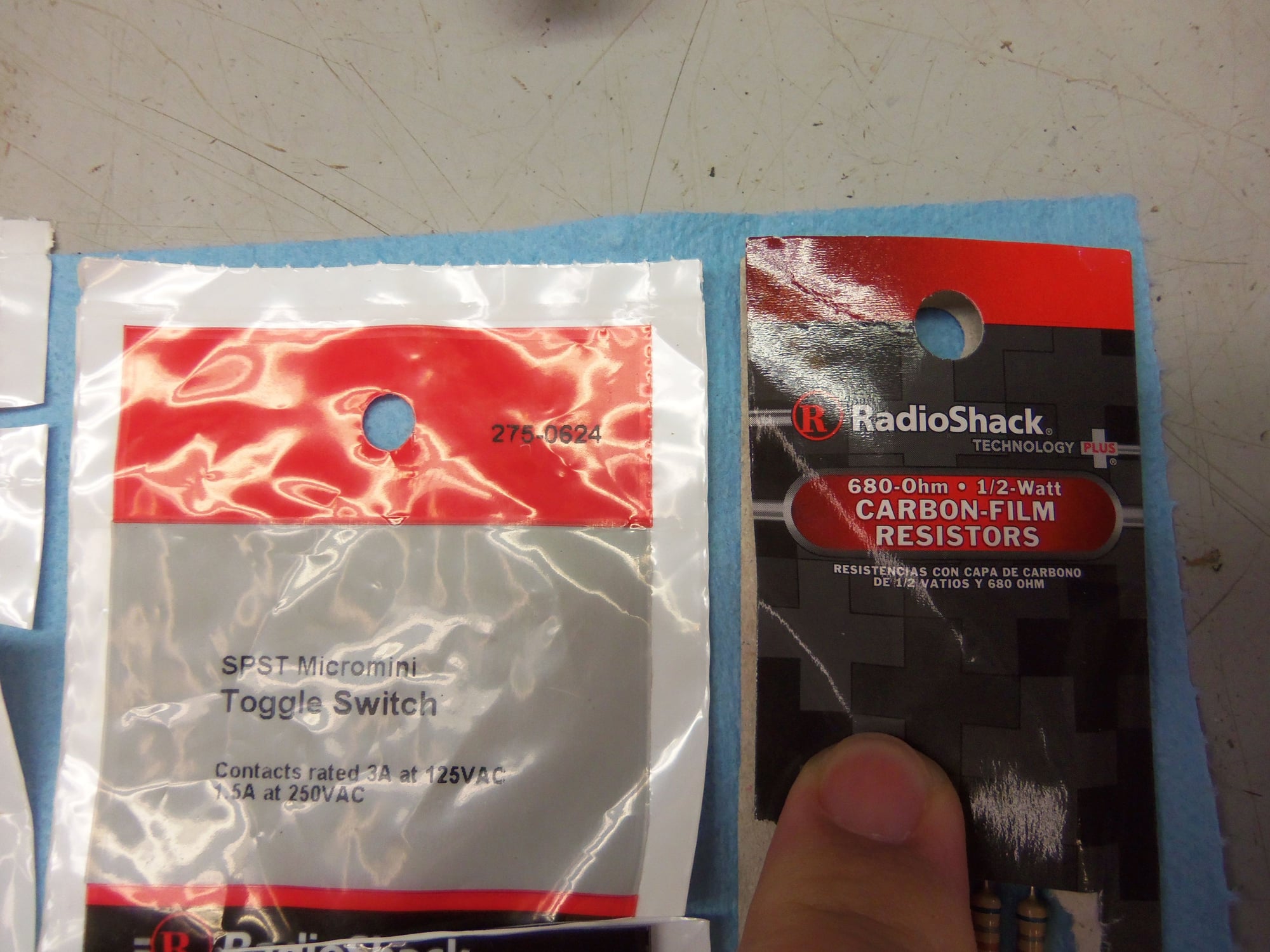
(1) 275-0624 SPST Micromini Toggle Switch
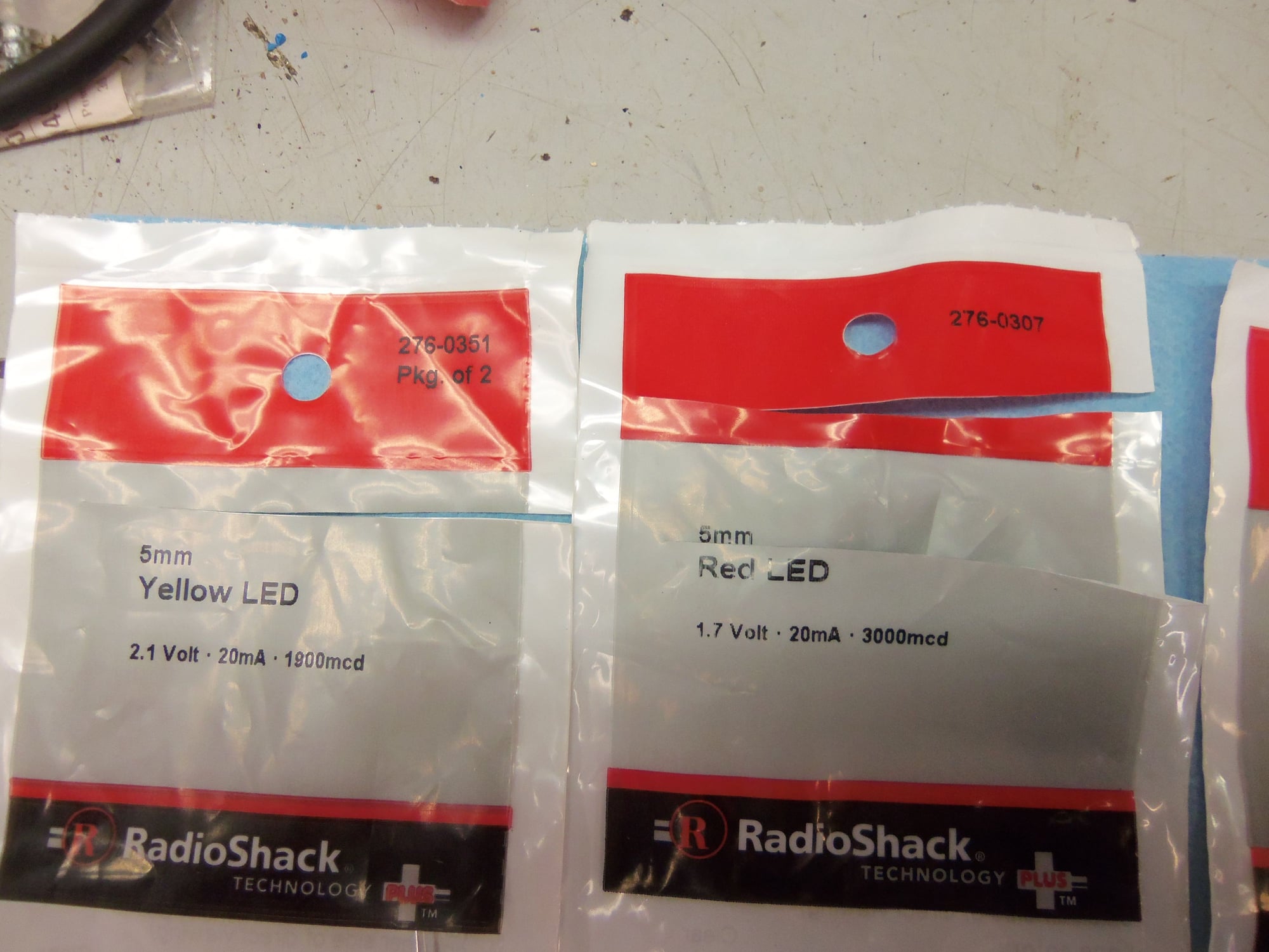
(1) 276-0307 5mm Red LED 1.7 Volt, 20mA, 3000mcd
(1) 276-0351 2-pack 5mm Yellow LED 2.1 Volt, 20mA, 1900mcd
(1) 2711117 5-pack 680 ohm 1/2 watt carbon film resistors
(1) 2710005 5-pack 100.0 ohm 1/8 watt carbon film resistors
(1) 2710013 5-pack 10.0 ohm 1/8 watt carbon film resistors
From my workshop, I sourced a red covered alligator clip, a length of 16 gauge red wire, lengths of blue, brown, black 22 gauge sensor wires, and various lengths of heat shrink tubing.
I laid out and drilled holes for the switch and LED's in the front of the case. The switch hole was a tad large, as I didn't have the exact sized bit, but the LED holes were spot on. They were a friction fit in the holes.
I built a test rig, doing the following:
680 ohm resistor to anode of red LED
100.0 and 10.0 ohm resistors in series of anode of yellow LED
Note, anode is longer lead, cathode is shorter lead. Anode is (+) voltage, cathode is (-) return voltage.
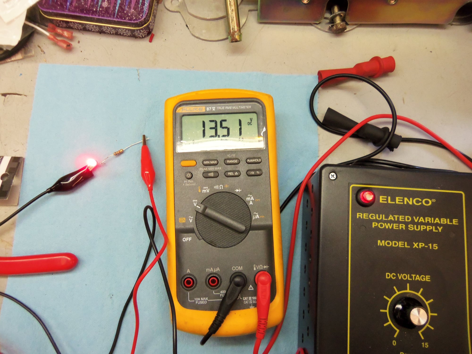
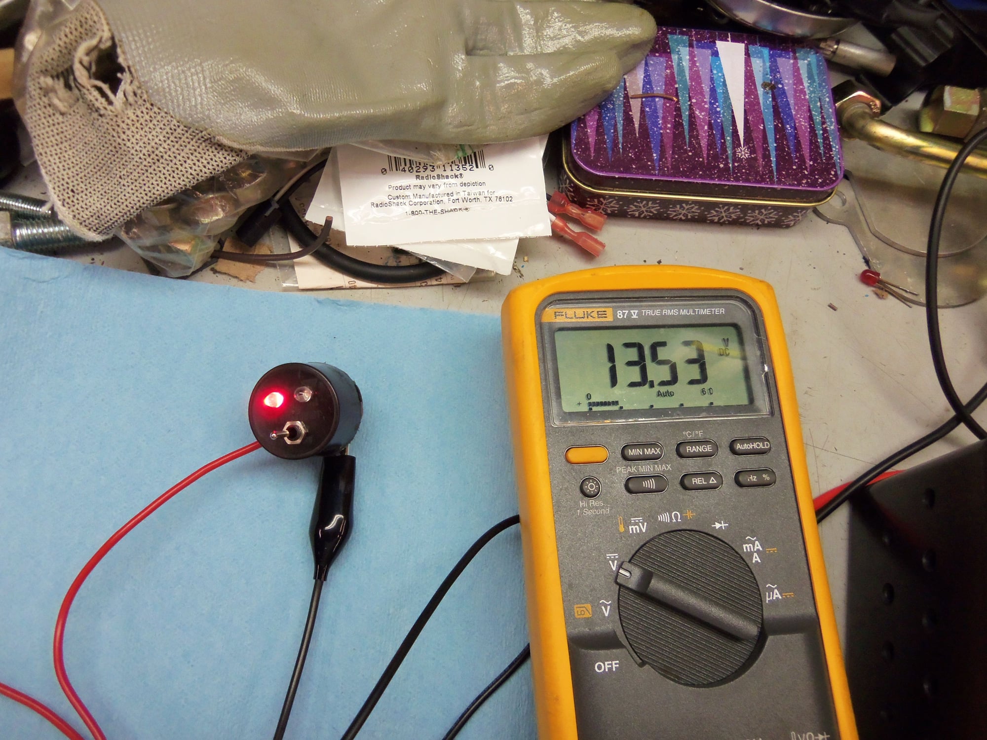
I set these up on a little adjustable power supply I made as a project years ago in school. It is adjustable from 0.0 to 15.0 VDC. I used one of my Fluke 87V's to measure voltage.
For the red LED, I connected the red lead to the 680 ohm resistor and the black lead to the short lead cathode. I walked the power supply up to 13.5 VDC, which I thought was representative of jump post voltage on an idling 928. The LED started dim, then was quite bright. I torture tested it up to 15.0 VDC just because. No issues.
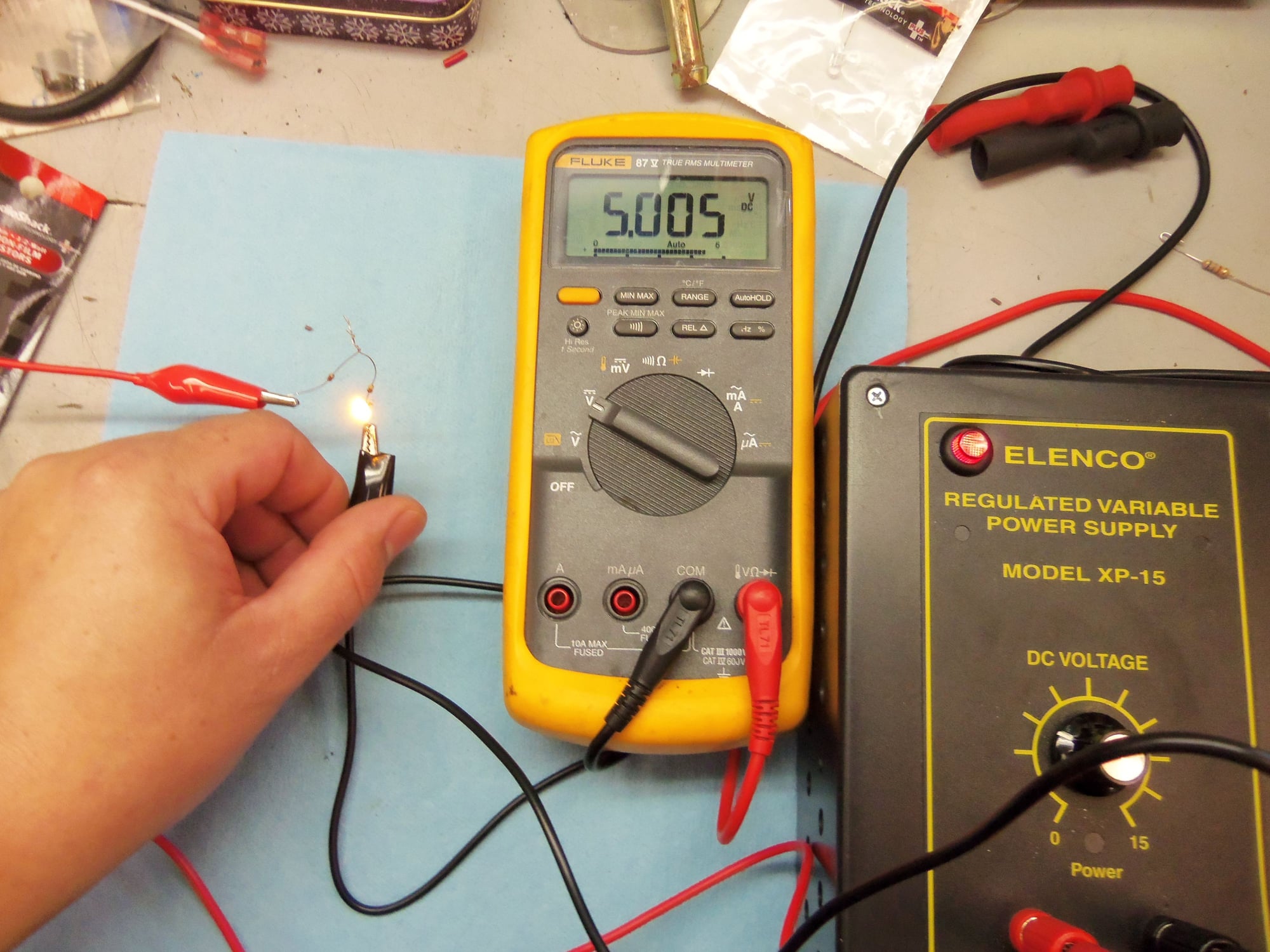
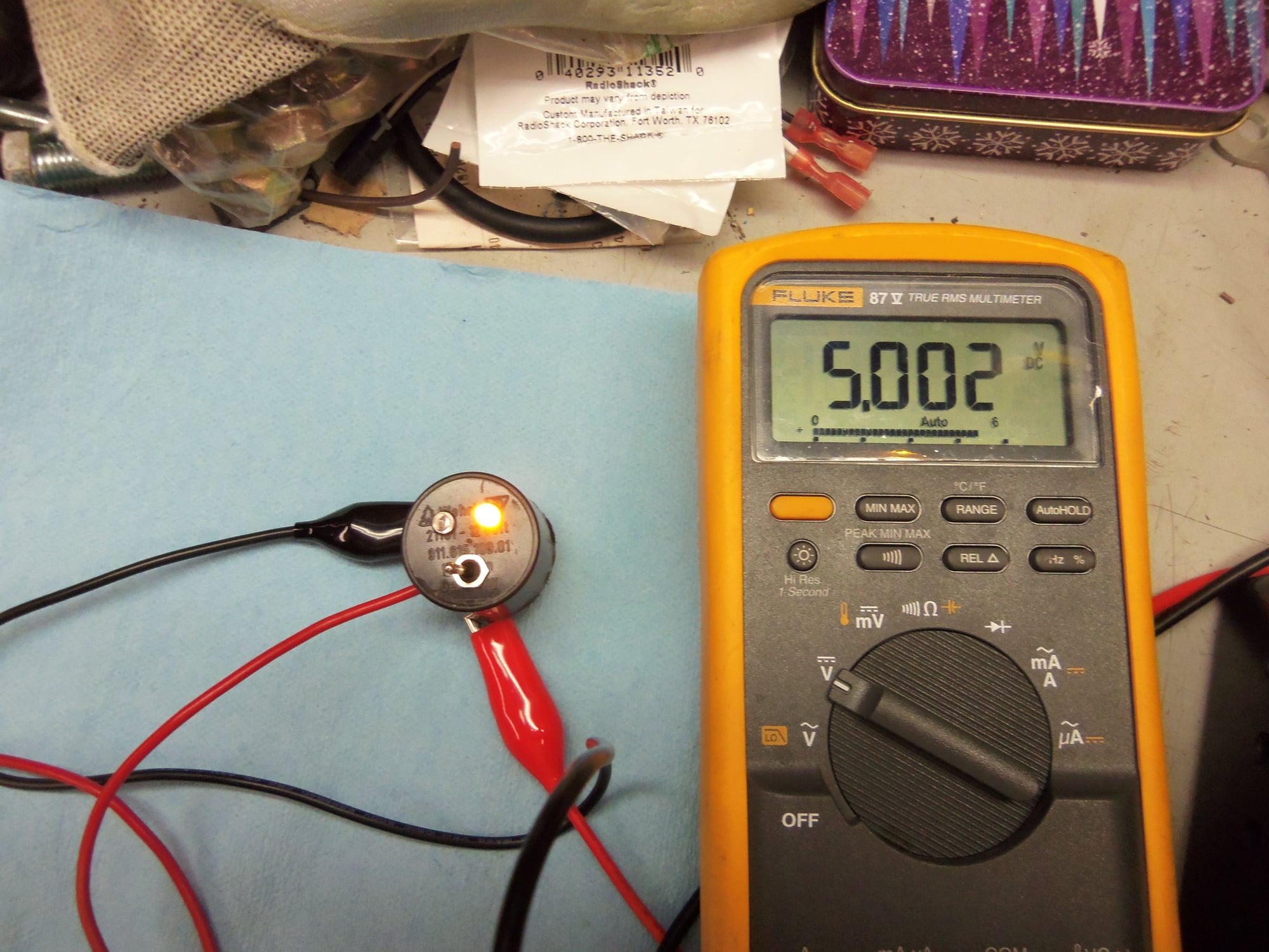
I did the same setup for the yellow LED, but held power supply voltage slightly above 5.0 VDC. It worked just fine.
I wanted to make sure both LED's were nice and bright so I could see them when using the Blink'r.
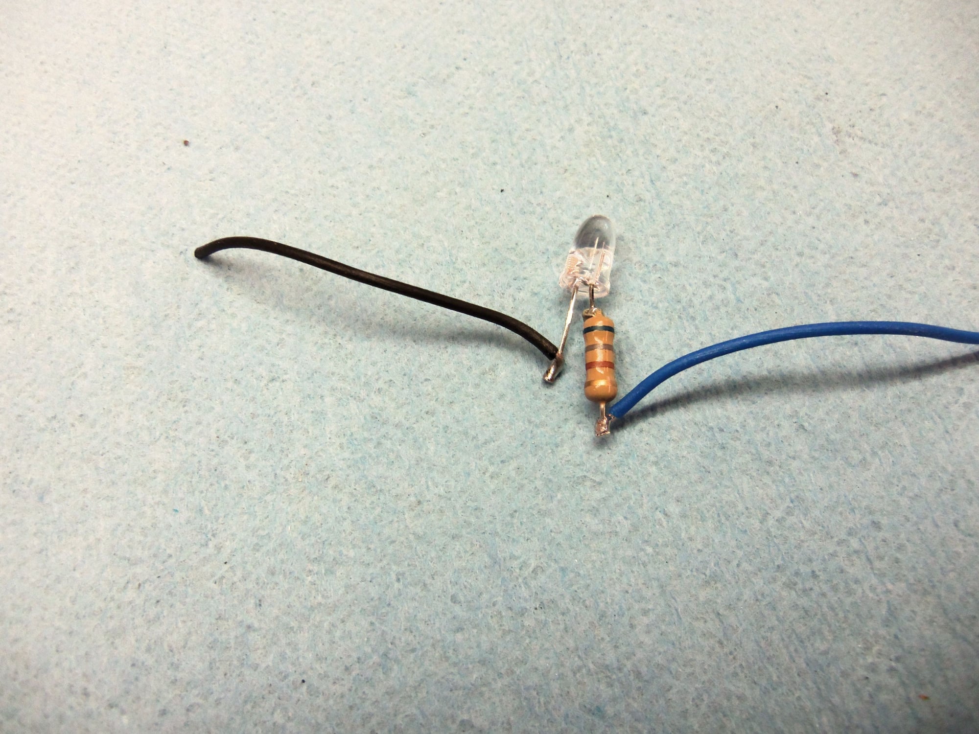
Testing done, I soldered the resistors onto the LED anodes in as tight a package as I could. I then soldered lengths of the sensor wire onto the resistors and cathode leads. All then got covered by heat shrink.
The terminals of the toggle switch were done in the same manner.
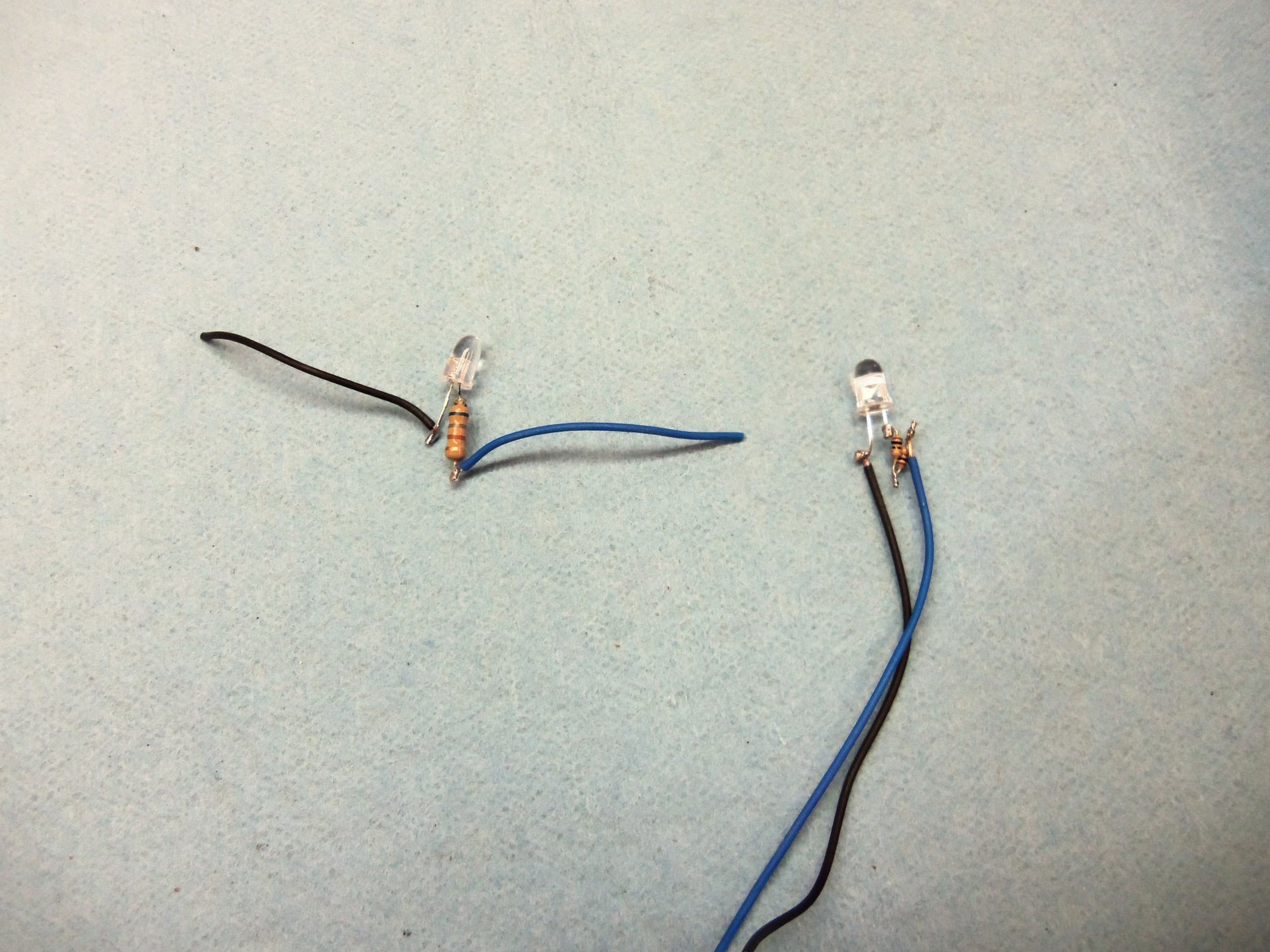
Red LED on the left, yellow LED on the right.
Red LED and 680 ohm resistor.
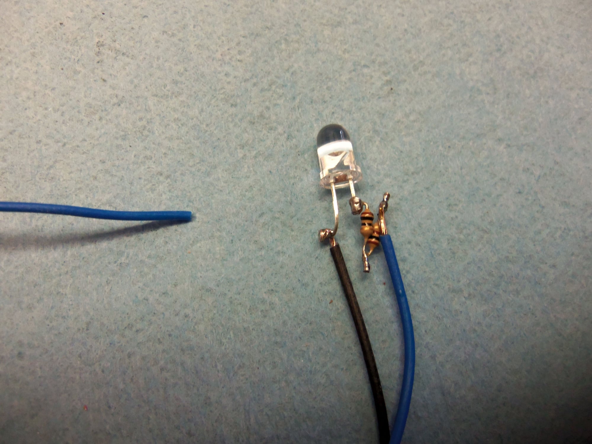
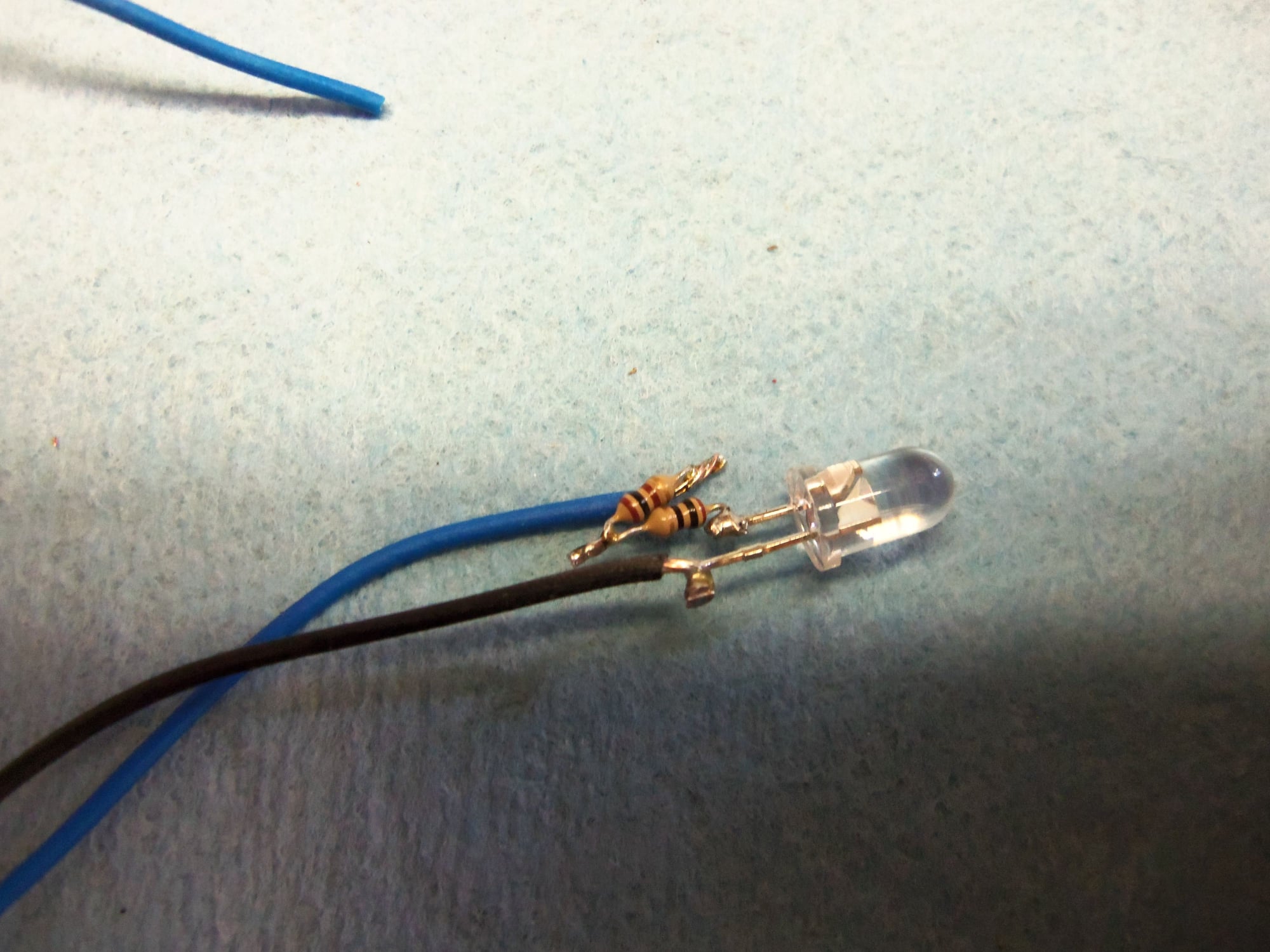
Yellow LED and 100.0 and 10.0 ohm resistors.
Another view of yellow LED and resistors.
I used my dremel type tool to remove the tall contact posts for the relay guts. I then used a grinding stone to remove the top of the metal post securing the plastic cap for the coil wiring. Man, that was alot of wire for such a tiny coil...
I was left with a large center post and the metal bracket for the contact arm. I was able to carefully pry the metal bracket off the center post without damaging the plastic backplane of the relay case. Then, it was a matter of twisting and pulling with pliers to get the metal center post out of the plastic backplane.
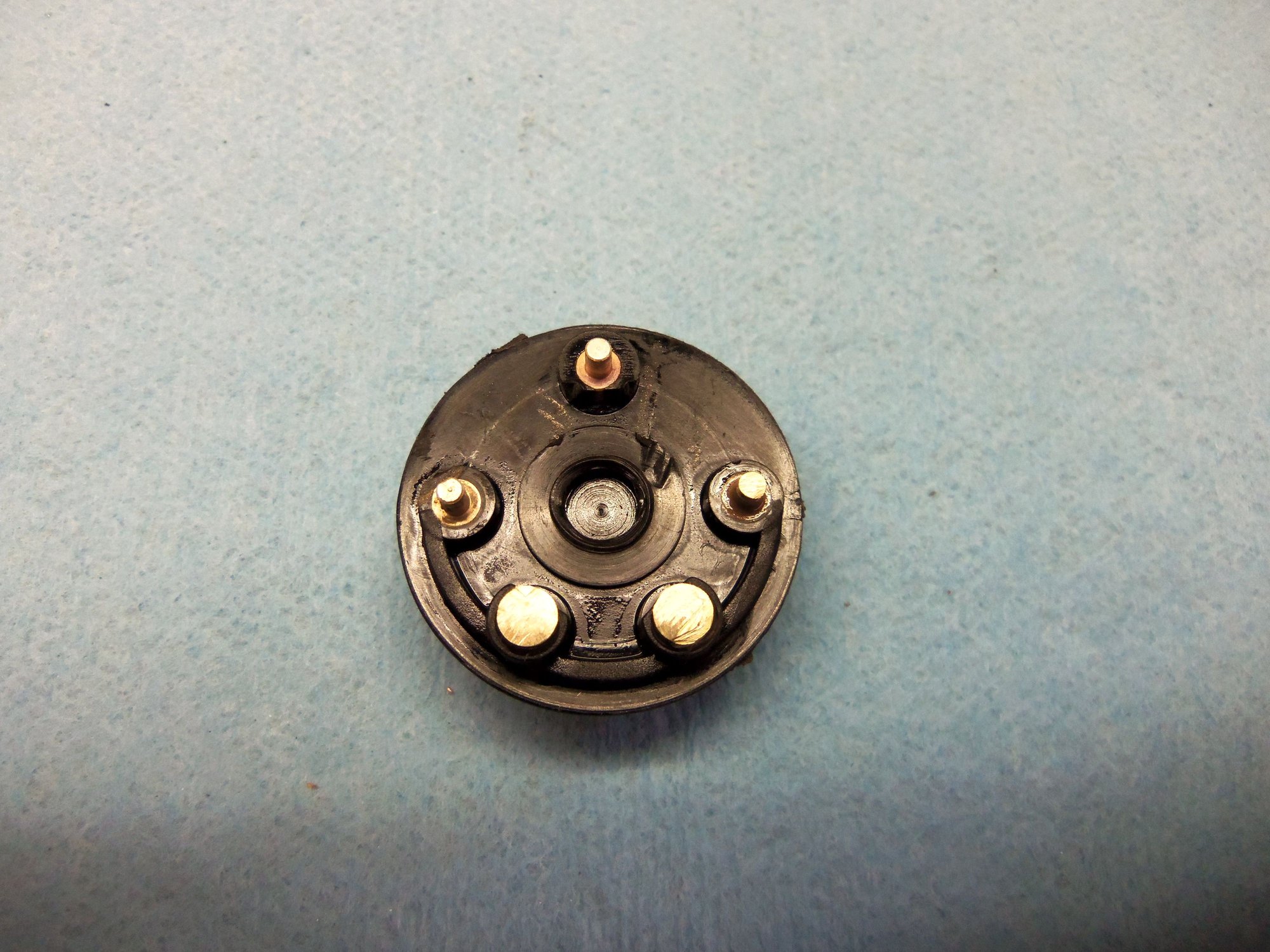
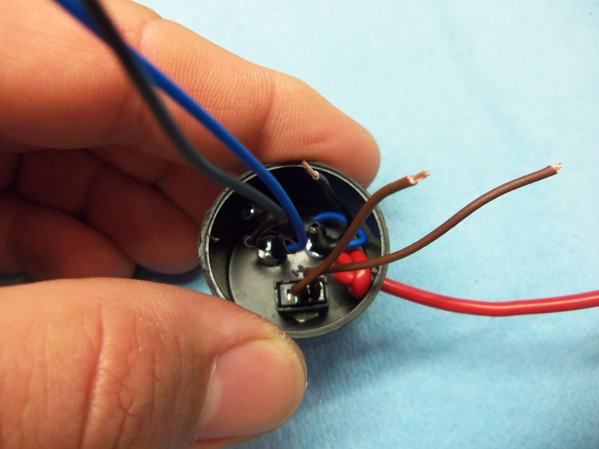
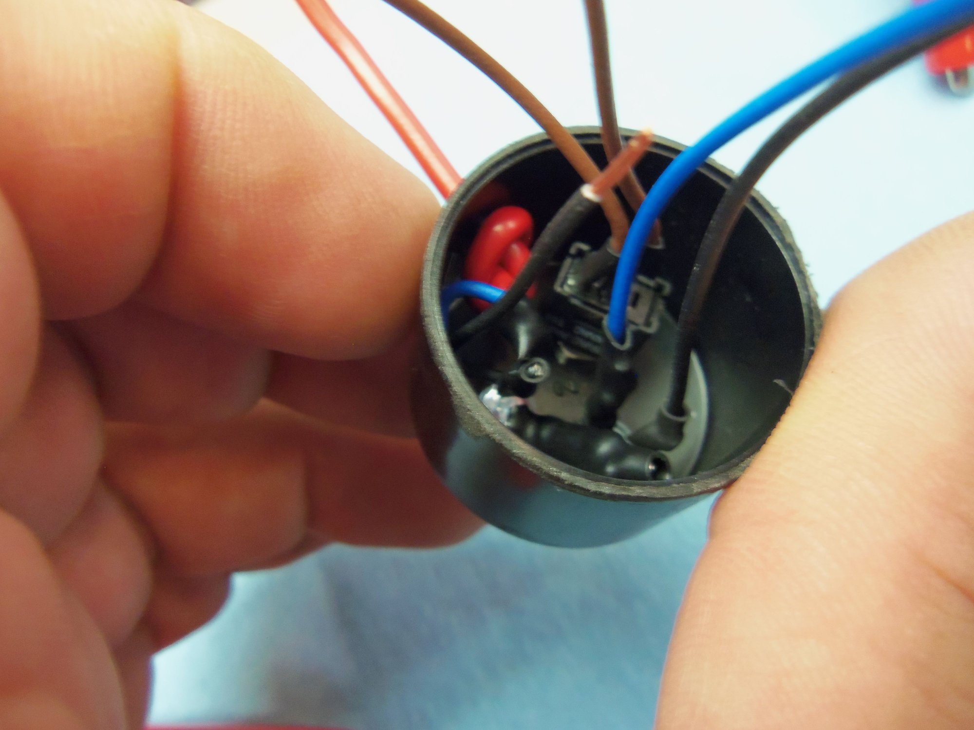
Inside of backplane, showing guts removed. Note cut off posts at the bottom.
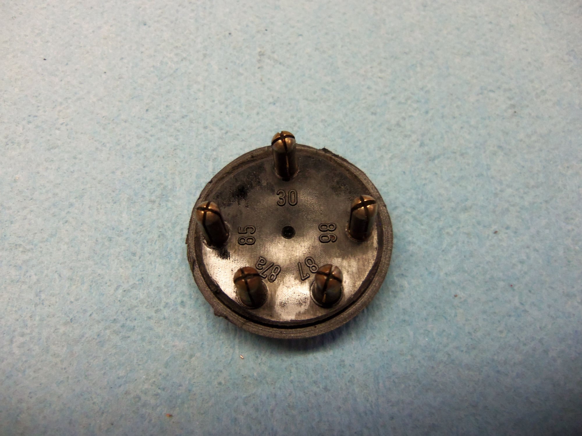
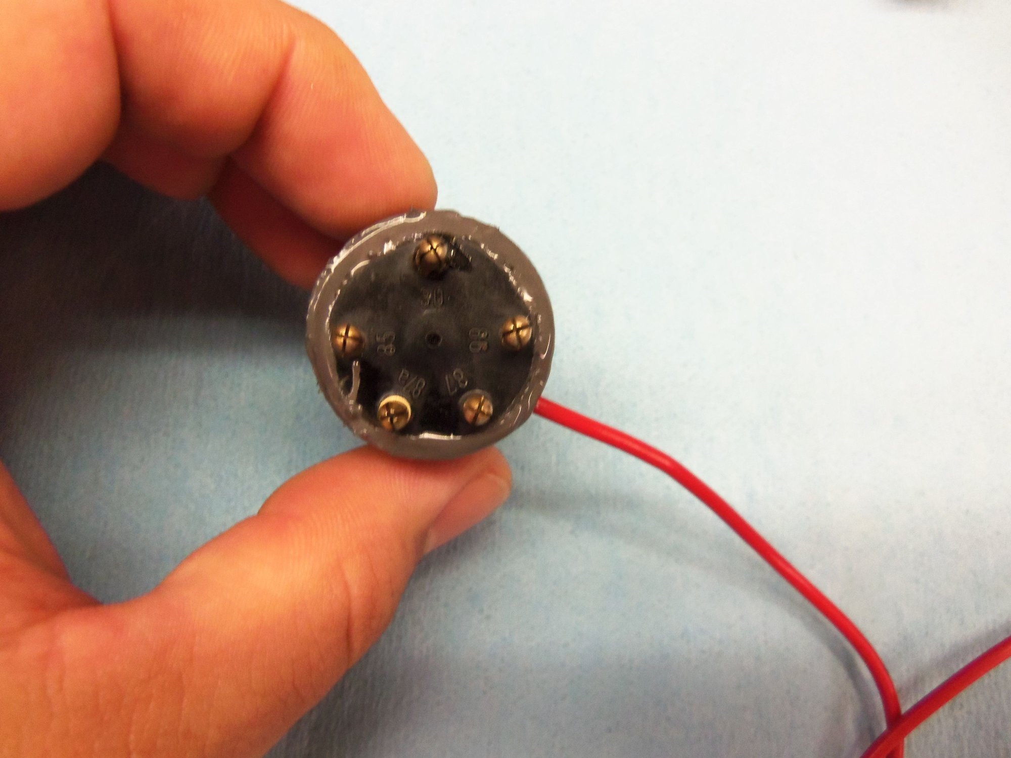
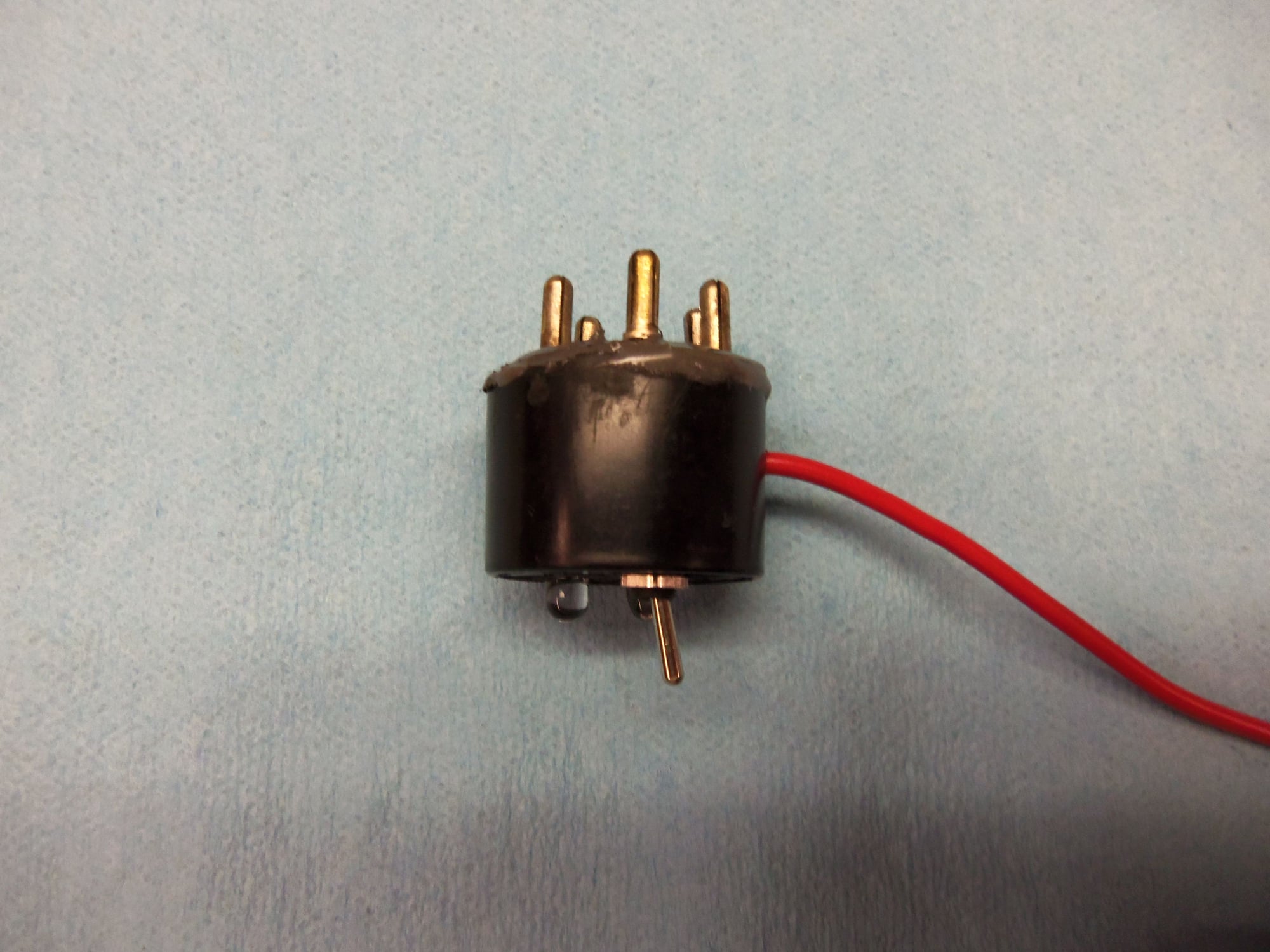
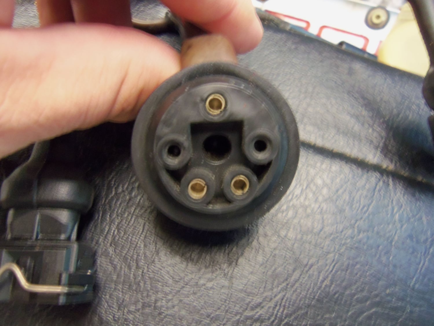
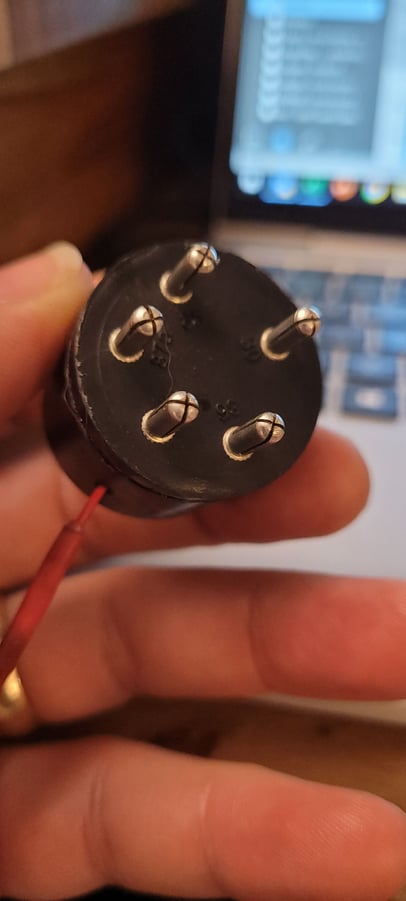
Backside of backplane, showing relay terminal posts.
I screwed this next part up. I cut my connecting wires too short. This left me with precious little room for soldering once all was installed. I installed the switch in the lower center hole, the red LED in the upper left hole, and the yellow LED in the upper right hole. I put a little epoxy on the backsides of the LED's in the case to hold them in place. I drilled hole in the side of the case for the red 12 VDC lead. I ran the lead through and knotted it as strain relief.
I will be upfront with this. Soldering to the relay case pins was a beyatch in high heels. At one point, I had so much heat in one of the pins, that it slid out of place in the plastic backplane. It took alot of heat and alot of solder to get the wires to stick to the relay pins. But, I got it. Yes, they are some UGLY solder joints. No, I am not proud of them. But, they work. And, you get no photos of the soldering.
After soldering, I tested everything one more time. Had to resolder the wires at the B terminal several times until it held. Then, reassemble the case and backplane with a layer of JB Weld. I managed not to make a horrible mess out of it. Not through lack of trying.
Once dry, one more test and call it good!
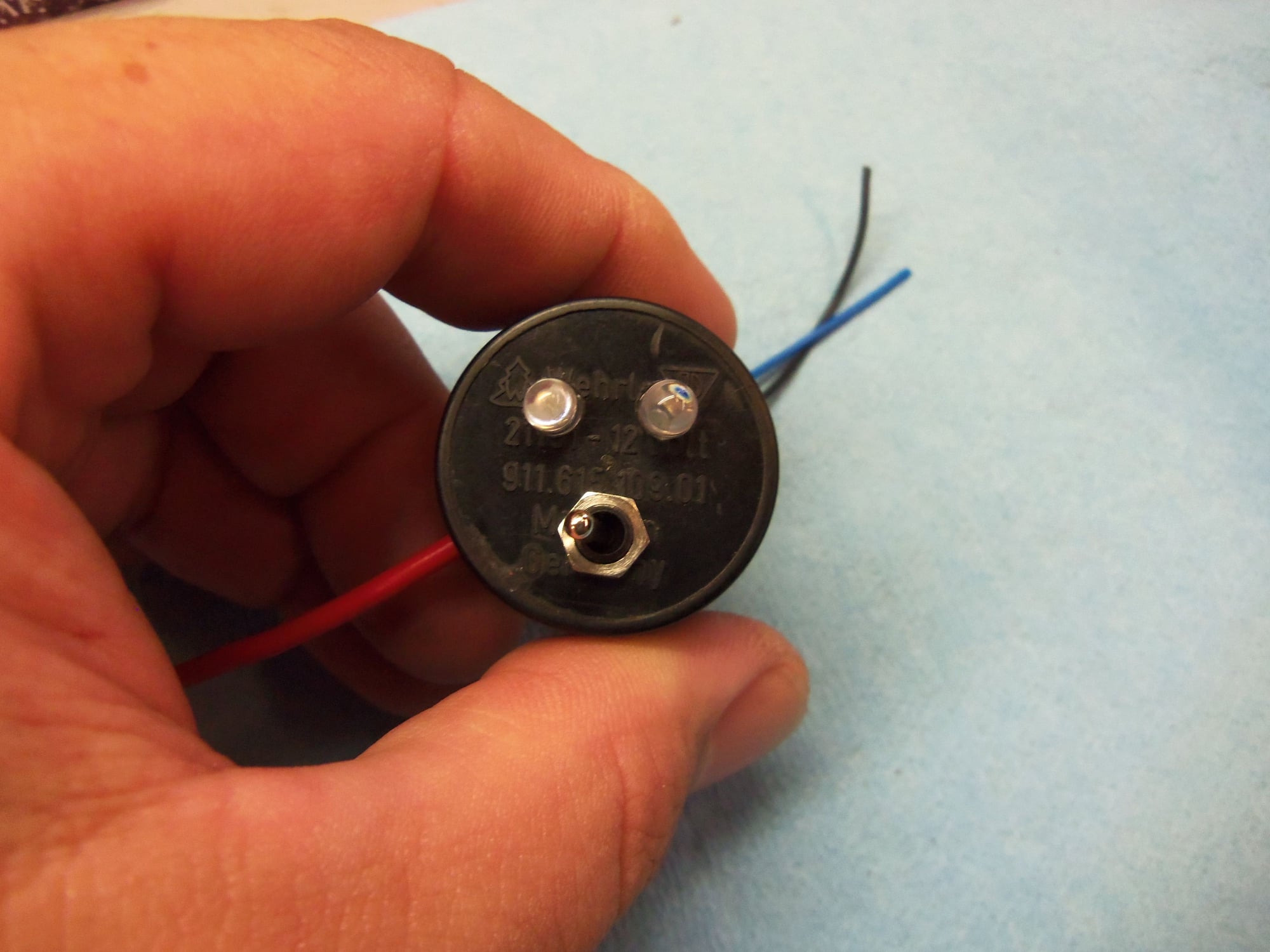
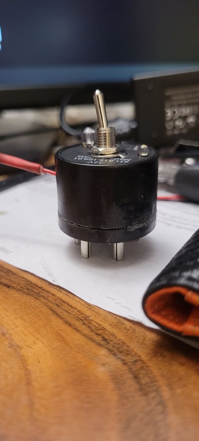
Completed Blink'r!
Successful test of red LED.
Successful test of yellow LED.
Also, for reference, here is a photo of the test port in the wiring harness for the S3. Note, top terminal is 'C', bottom left is 'B', and bottom right is 'A.'
As you know (thanks for the guidance on relay dismemberment) I'm doing the same thing, with (initially!) lower success. I didn't remove the relay, just the switch lever, and soldered to the relay posts. That actually seemed to work OK, but I seem to have messed up my switch, or else I got a bad one, because it's not switching anything. I'll fix it...but for now I got annoyed and just stuck a wire in the two ports for my immediate needs.
This thread is a nice reference, for anyone making these going forward. Thanks for documenting!
Note on the WOT circuit - IIRC, through trial and error, I had to put in a larger resistor than I calculated for the WOT LED I used to keep the LH from thinking the WOT was on all the time.
(The WOT input is variable, wired to a A/D converter, IE. they could have used a pot instead of a switch.)
Originally Posted by skpyle
The frustration of doing this multiple times would surely push me right on into alcoholism.
Note on the WOT circuit - IIRC, through trial and error, I had to put in a larger resistor than I calculated for the WOT LED I used to keep the LH from thinking the WOT was on all the time.
(The WOT input is variable, wired to a A/D converter, IE. they could have used a pot instead of a switch.)
You can test WOT at the LH connector...that's how I did it. I put a pot on that...like Ken mentioned. What I found out on my car is that increasing the resistance on the line changed more than just WOT...interestingly enough....Ken..did you have similar experience with yours? Just wondering...
@skpyle (or others since this is an old post), First, thank you thank you.
Confused on a couple details:
> Is "high load throttle" synonymous with the switched state of WOT
> Is a Blink'r comprised of two unrelated circuits? In this example, is the yellow LED circuit separate and isolated from the red LED circuit?
> Are the correct assumptions that the yellow LED:
indicates a bridged connection between |B| and |C|,
is performing the bridge,
the yellow LED is energized by the 5VDC on |B|,
and is the only switched bridge?
> Is the red LED an un-switched bridge between |A| and the 12VDC passenger-side jump post?
Hi meatful!
To be honest, it has been a few years since I did this and thought about it. My Red Witch is still languishing on liftbars. I am not done with her yet.
I will strongly suggest you look at the two links I posted. They helped clarify things for me when I built it.
I am not trying to blow you off. I just don't want to give you the wrong information when I am not familiar with it anymore.
So after a few epiphanies and lots of fiddling I built one! Great exercise. The fog cleared when I realized that a) the lit yellow LED is simply a visual confirmation that B and C are otherwise bridged, and that b) the red LED (O2 pulse output) is not electrically associated with the yellow LED or switch whatsoever.
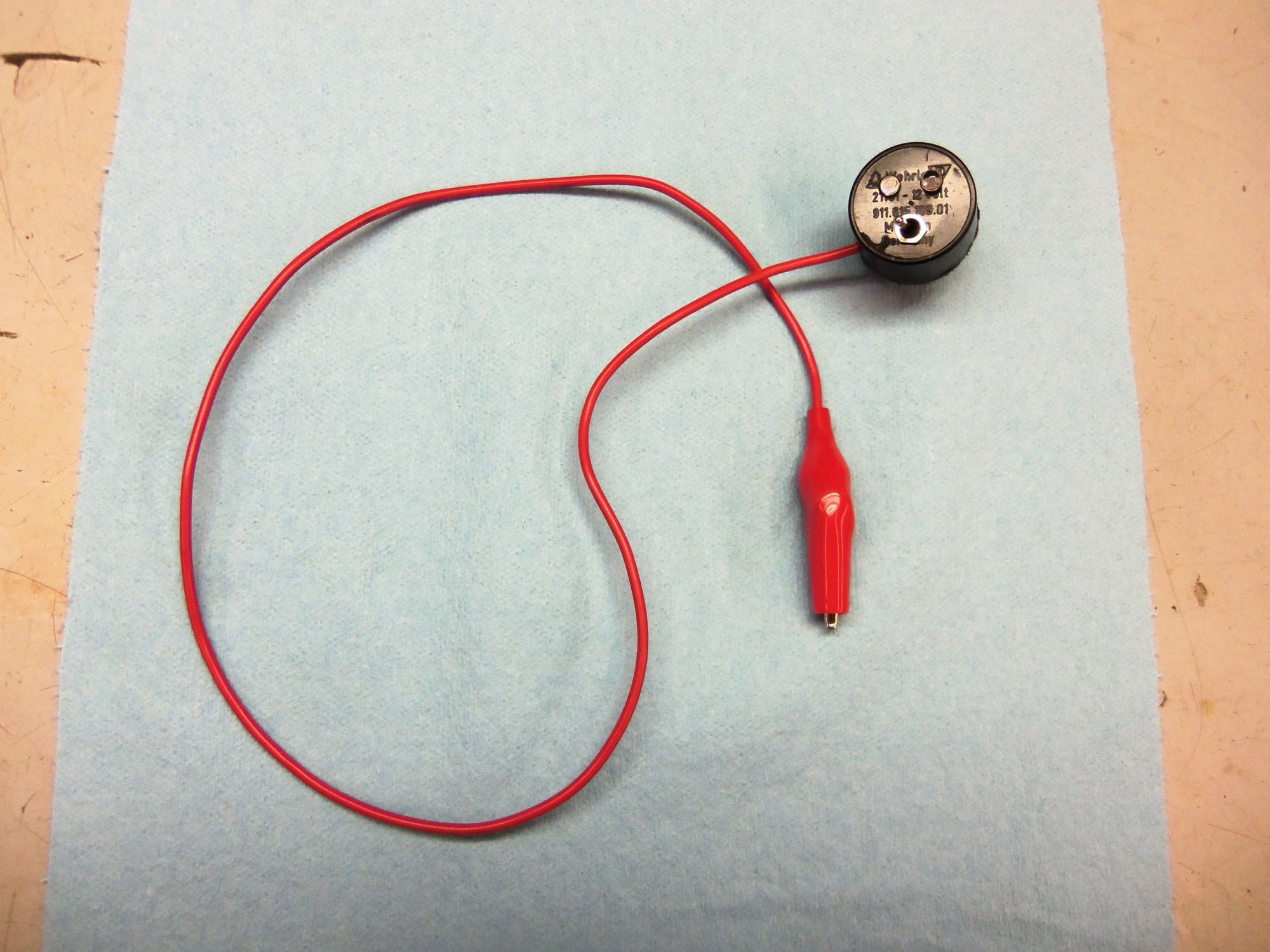
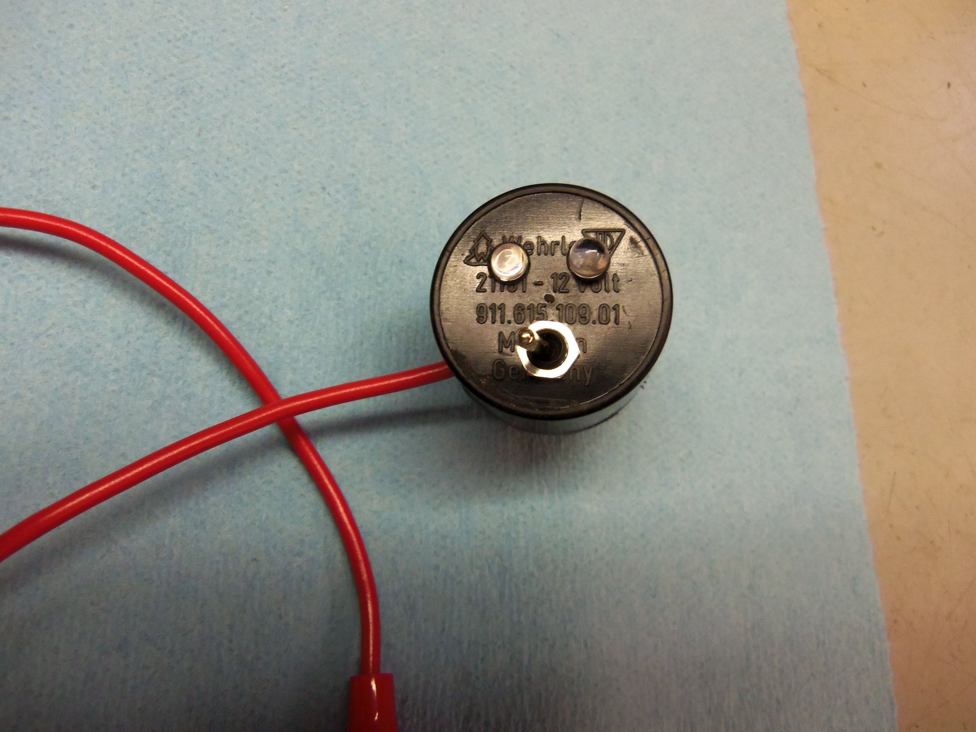
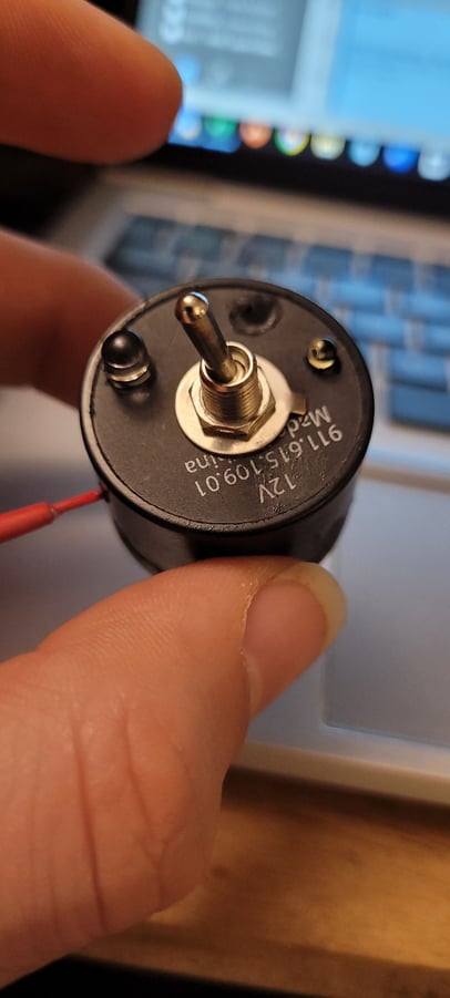
Thanks for posting an original writeup as years later it was a big help. Below are pics from mine.
Gutting the 914 relay was pretty easy with slow twisting motions from pliers. I opted to fill the cavity with epoxy (because you never know when you need to protect a blink'r from 40Gs of acceleration, lol).
DIY blink'r side view DIY blink'r posts DIY blink'r front

 06-25-2017, 10:25 PM