When you click on links to various merchants on this site and make a purchase, this can result in this site earning a commission. Affiliate programs and affiliations include, but are not limited to, the eBay Partner Network.
but ive been driving my race car on the street for many many years with NO problems!
the standard S4 pump is used on street cars, returning much of the fuel to the tank with no issues.
ive sat in traffic for hours with the race car as well, but the pump doesnt know its a race car , so are we talking pump or injectors.
i have used the 30lb or 19lb injectors with the stock pump.. also, i run the tank always at 1/8 tank, and not much more unless im in a race, where it starts out at 1/2 tank. never had an issue............... my question, is what issues are you looking for?
ill take my race car out today, and just put around. i could measure fuel temp if you would like after a half hour run. all part throttle or idling around. its going to be cool. ive actually pulled the fuel line cap off after running and the fuel is not warm that comes out. ive had dripping out the rear of the tank at the fuel pump and the fuel was cool. i can check the fuel in the tank from the filler to see if it is warm.... it wont be i would bet.
but ive been driving my race car on the street for many many years with NO problems!
The stock regulator works pretty well with a single 044 pump, in my experience. The fuel heats up, but not enough to cavitate the pump. AFR will go a bit lean though when the tank is low.
Are you using the stock pump or 044 pump? Because the flow rate is very different.
Also one question is what level of a problem would register on your radar screen?
Impossible for me to explain the fuel pump/regulator problem any better than what Tuomo has done in post #750 and #752....he's got it figured out.
I'd only add that fuel heating is a problem, when things are not balanced....even in race cars.
Yes, there is not a problem when the engine is running at higher rpms and using most of the fuel volume. However, if a race car is caught in a "yellow light" situation for several laps, the fuel can get very hot, very quickly.
I was talking once to my good friend Chris Cervelli, who lives in Denver (high altitude). One of the problems up there, where the atmospheric pressure is slightly lower, is that people add bigger pumps to increase the volume (because they think this is a good idea.) This can raise the fuel temperature, like we've talked about, here. They actually end up getting the fuel temperatures high enough to vaporize (boil) the fuel, when the cap is removed from the tank (remove the pressure.)
According to Chris, this is a very common problem.
I think the entire point of this discussion about making intake manifold changes is very simple.....when redesigning something, there are obvious issues that need to be considered and not so obvious issues, which may also be important and need to be addressed.
Each change in a system can require many other changes in order to function correctly. The "art" of making something work well is to consider all of possibilites and change your design, if necessary.
Interesting that Bosch prescribed a higher-pressure pump to try and solve fuel heating problems on early CIS cars. That helped with boiling in the rails but exacerbated the total heating problem... Which ultimately made boiling worse in the lines. The fuel coolers in the 928 are there for a reason.
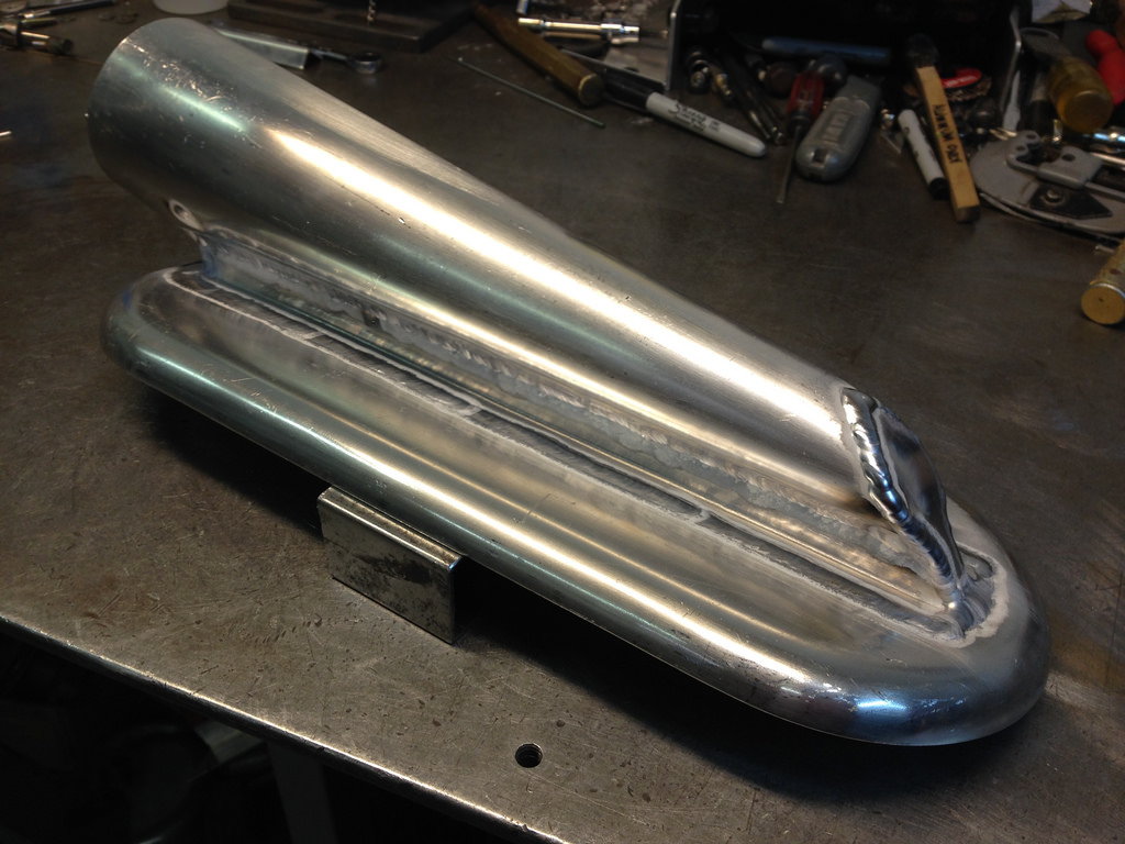
The lower cant be modeled until I have some time to play with the throttle location to make sure we can get the Y-pipe to clear the fuel cooler and all the other stuff by the firewall. I hope to get that done this weekend, but its already pretty full. Its getting darn close, but still some things to figure out, such as throttle actuation, throttle location, tps adapters... but those should all come pretty quickly after the lower plenum design.
So, here are some captures from CAD as well as a fully manipulable 3D model for your consideration:
Took a look at your rendering. That's a good design, in my opinion. The plenum roof is high enough that you have a lot of options for designing a lower plenum that distributes well. The plenum volume doesn't matter in terms of tuning for this kind of manifold, which gives you a lot of freedom. If your throttle body stays at the currently modeled location, there's going to be some careful thinking needed to feed the two back cylinders as well as the rest. If you make a flat box plenum and feed it with a pipe from the center, you're guaranteed to get the distribution correct. But it's not the simplest design to fabricate, in my opinion. A lot of work left, but progress is impressive.
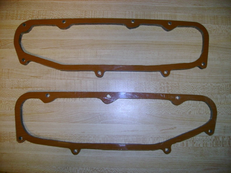
Thanks to Hans�s pictures it looks not to be very difficult to fabricate the intake. I like metalwork and I am in the possession of a complete workshop. However I will refrain in favour of my own design or Mr. Brown will call me a copy cat.
The intake gained a good 50 rwhp on Rob Edward GTS stroker, not bad. Post #183 https://rennlist.com/forums/928-foru...udy-hp-13.html
�ke
Last edited by Strosek Ultra; 04-17-2016 at 08:09 AM.
I'll be back soon to complete explanations, but for the moment many image sets are reasonably self explanatory.
Cheers
Upfixen
Originally Posted by Strosek Ultra
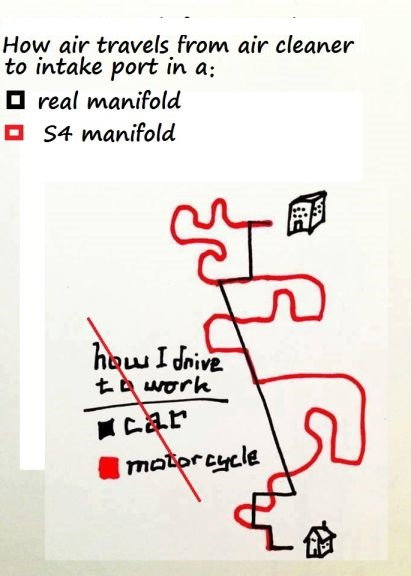
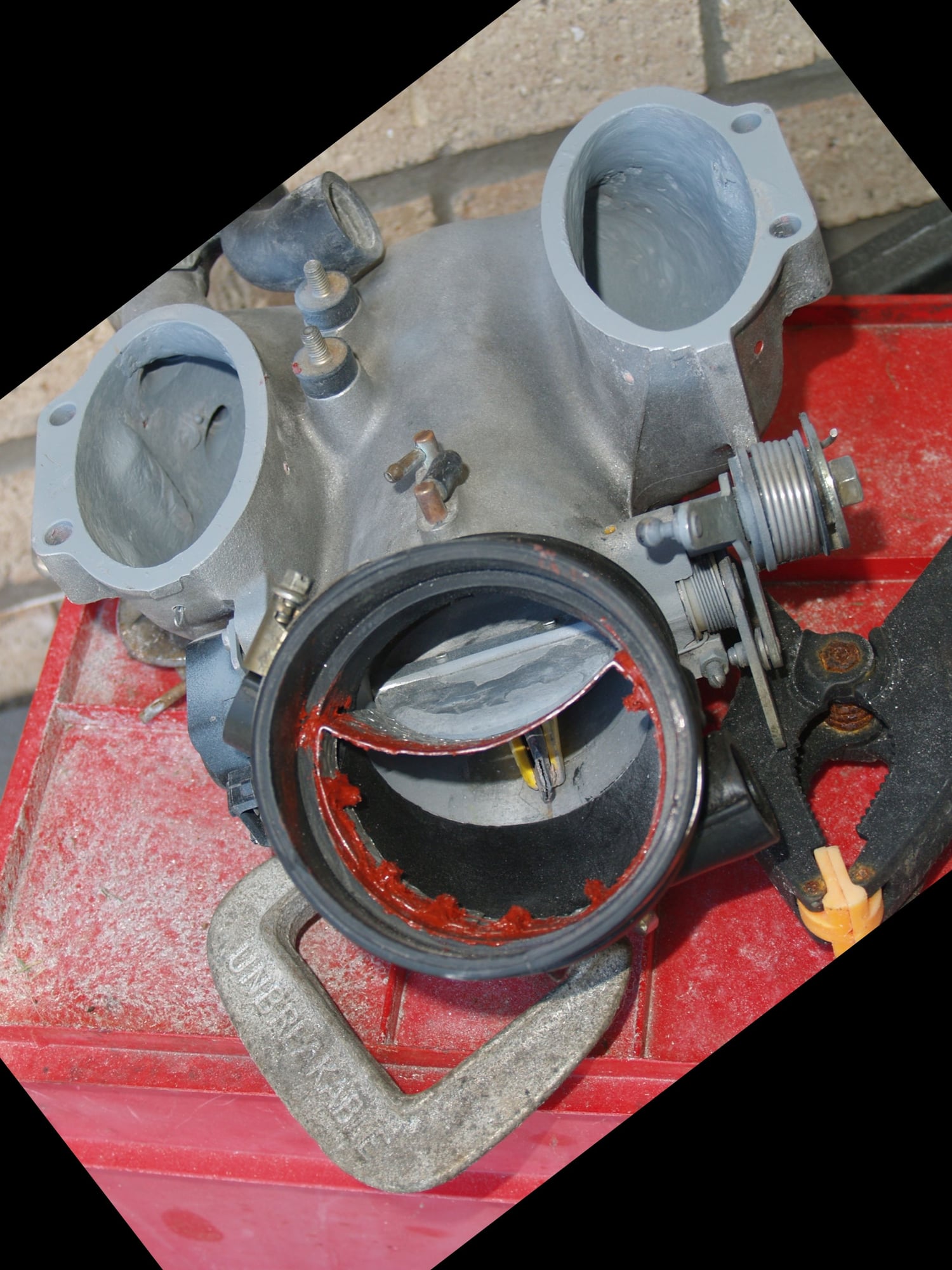
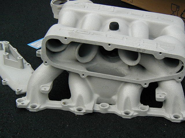
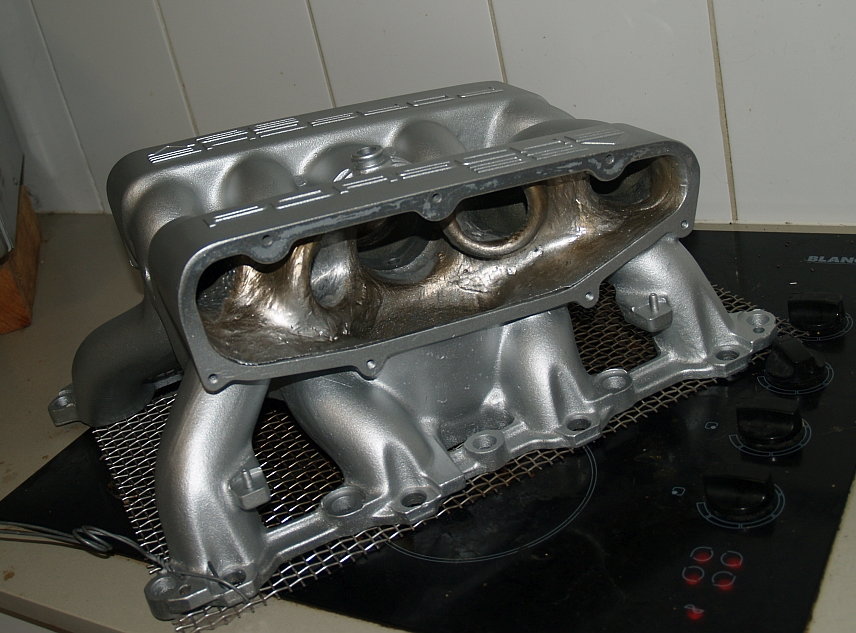
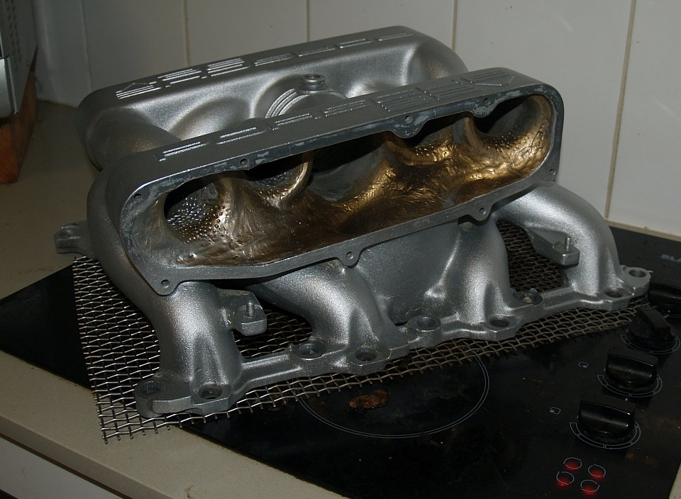
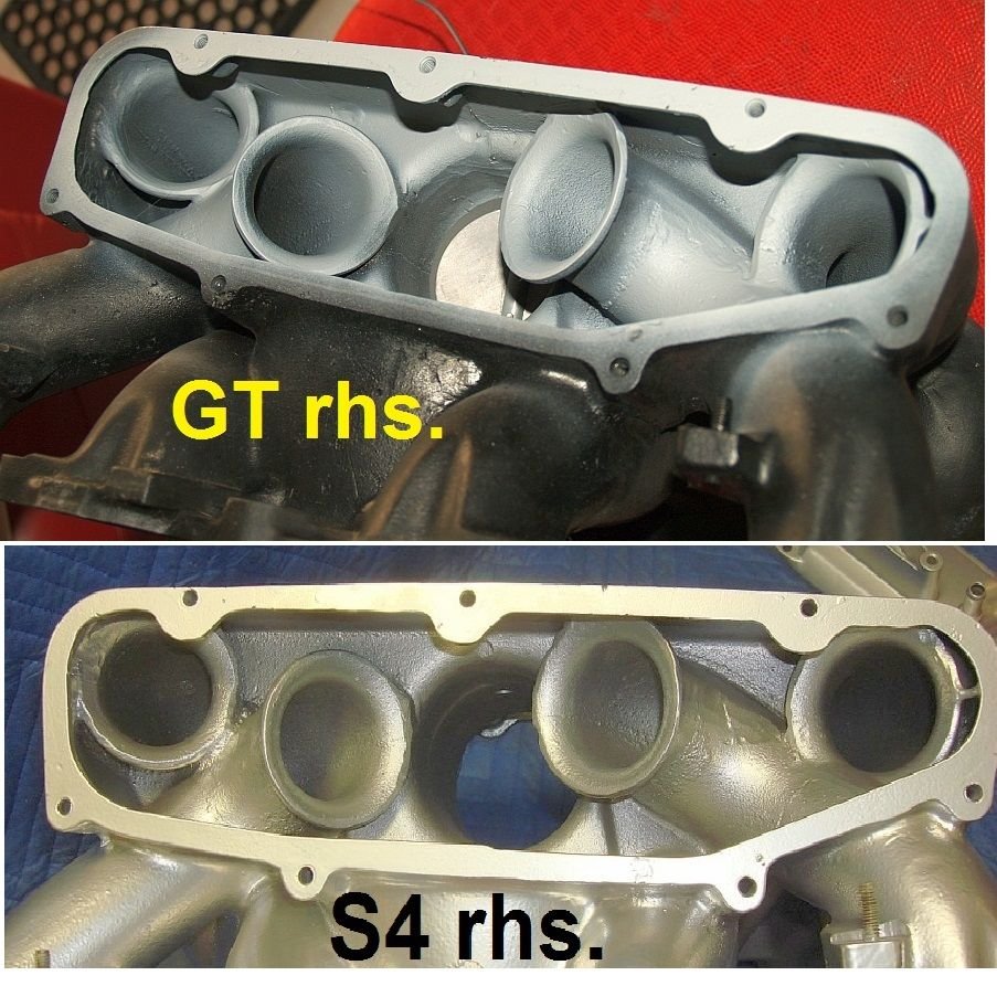
If you have a look at the complete intake system of the S4 engine, the air from the front of the car is passing through very long air ducts to the air filter housing, through the air filter, mass airflow sensor, throttle body and up the intake manifold, where it turns several times before it passes through the curved runners, and then into the intake port and behind the open intake valves.
Compare it to an ITB intake where the air has a straight shot down to the intake valves. That is a massive difference. Not only the intake manifold has to be considered when designing a good flowing intake system.
�ke
You hit the nail on the head Strosec, , and, might I say, seem the only Rennlister who has shown this level of understanding of the airflow problems.
Everyone else is capable of amazing machine work, but with airflow they're stabbing in the dark, and with moving air you just can't do that.
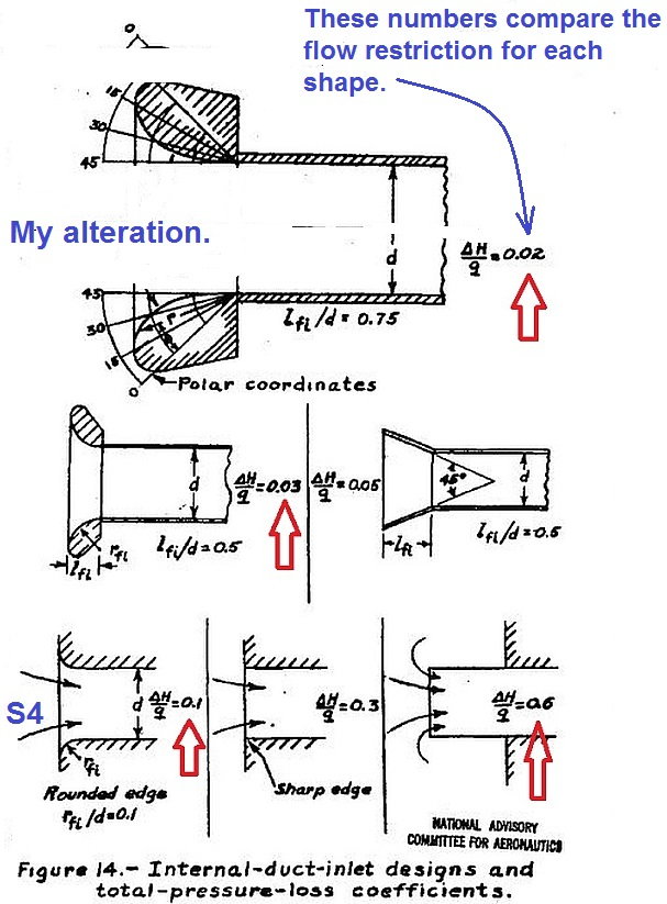
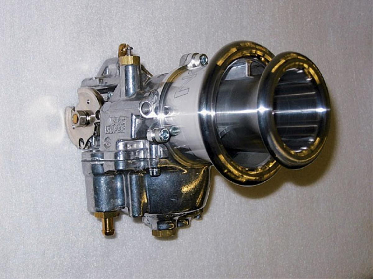
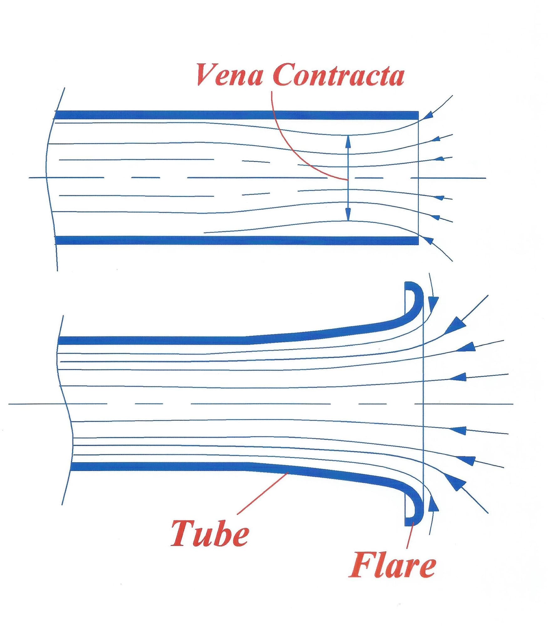
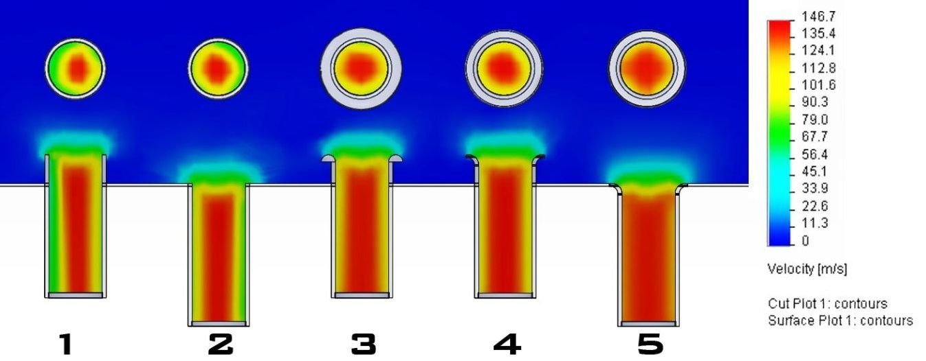
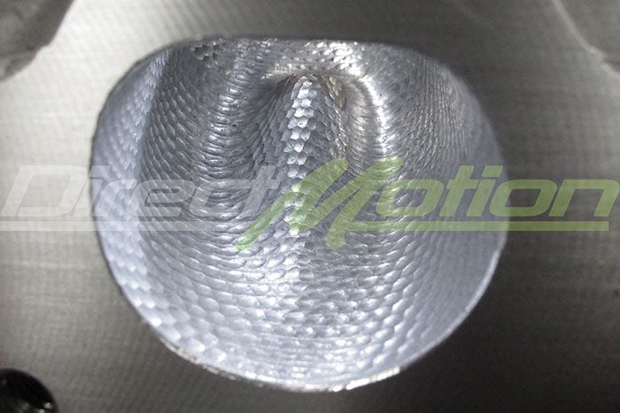
Below I've posted a spread of stuff out my "aero" library. It shows the why's and wherefore's behind my intake manifold performance gains, and the subtleties of airflow behaviour.
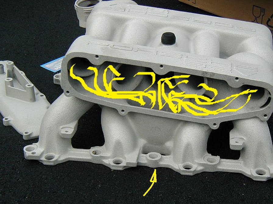
Intake air pathway on 928 S4:
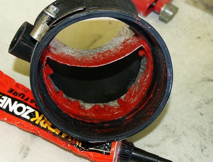
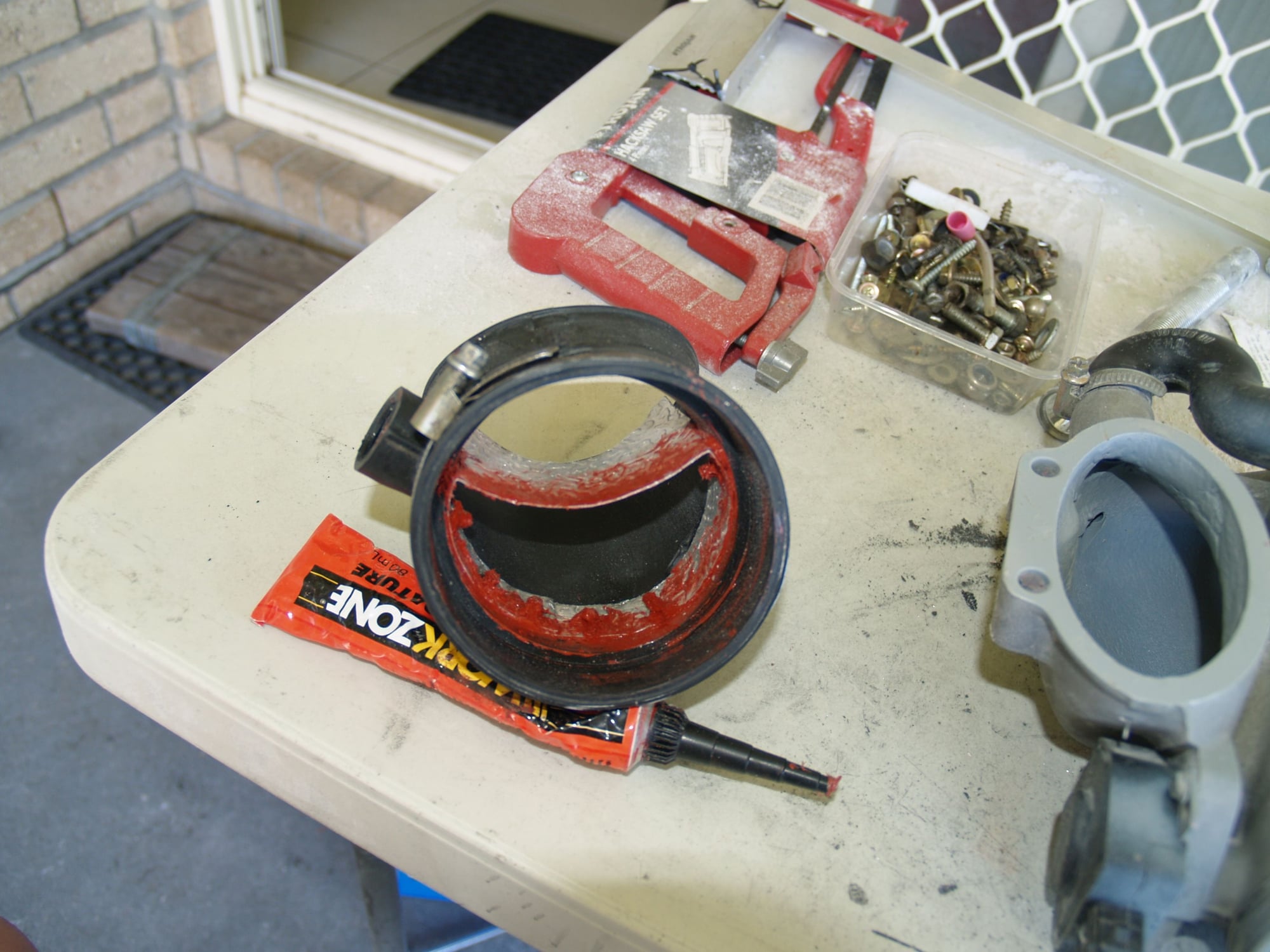
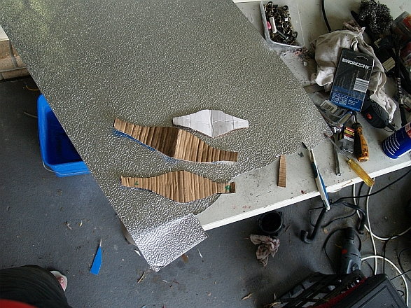
An understanding (and application) of this was at the core of my S4 intake manifold modifications.
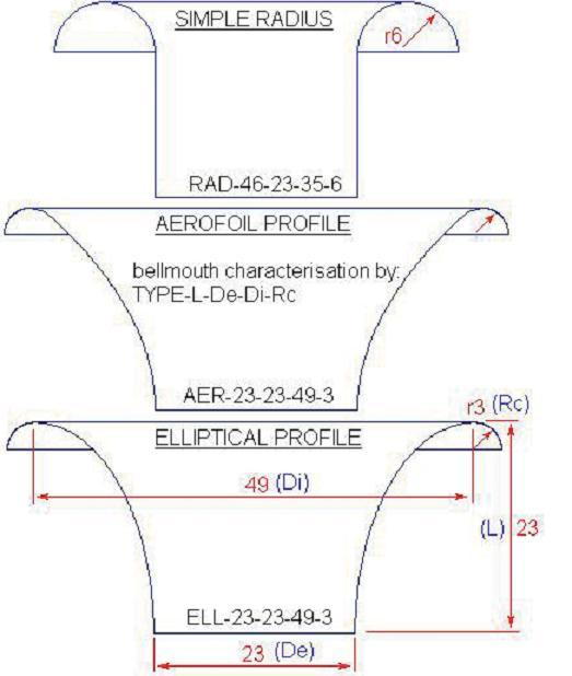
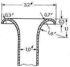
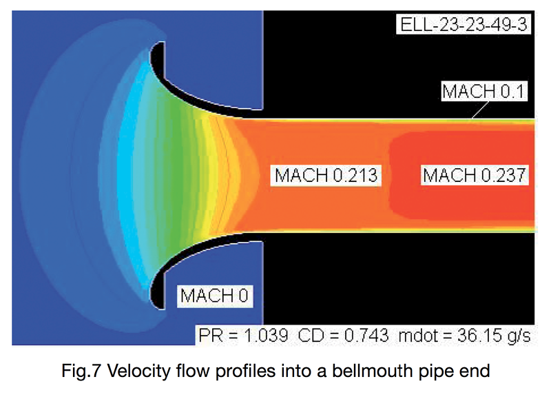
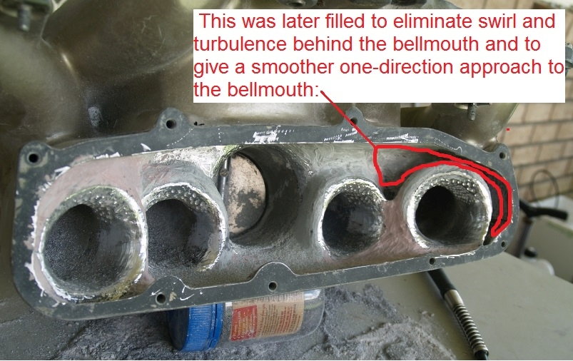
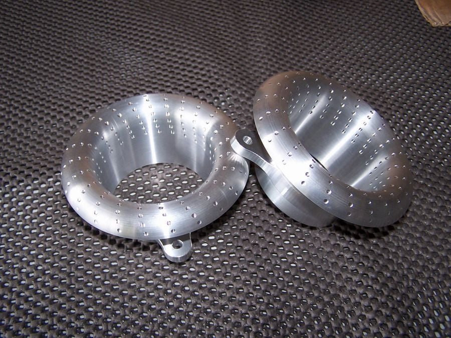
It centered on airflows at the pre-TB elbow (fitting a splitter), TB plenum (another splitter), and upper plenum intake bellmouths and runners (tapering of intakes and forming mathematically optimum bellmouth lips).
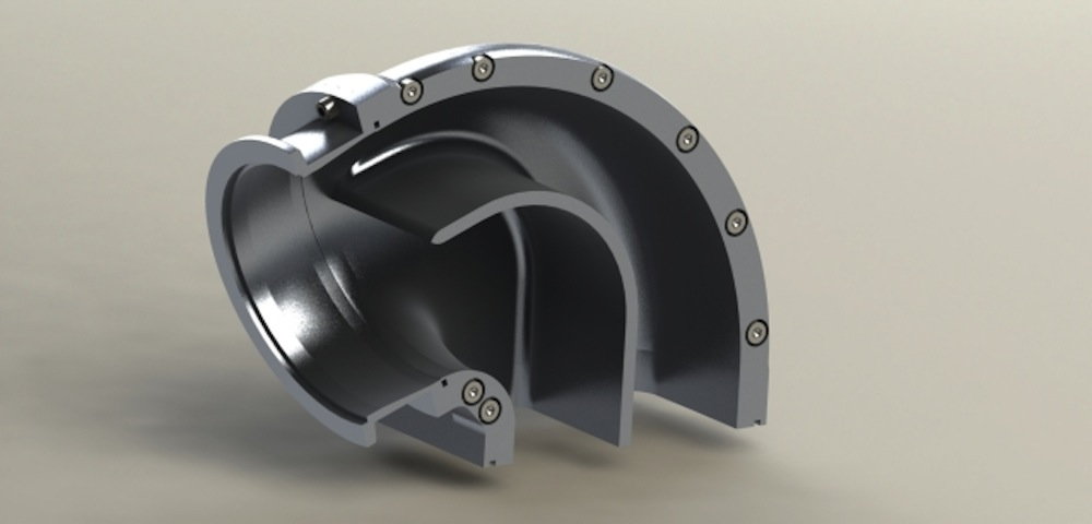
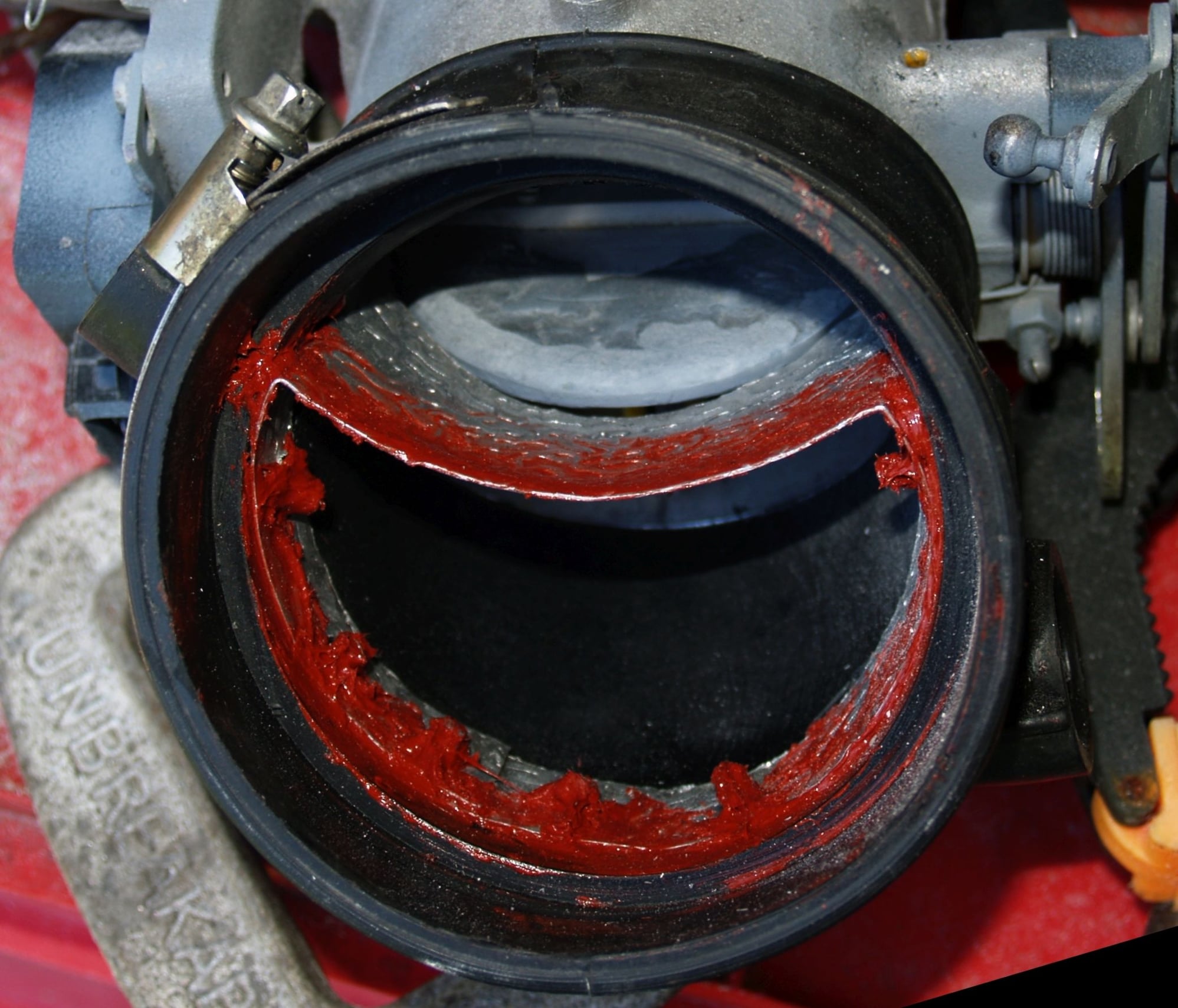
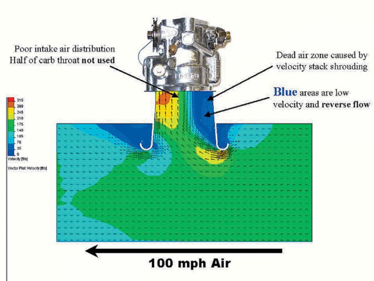
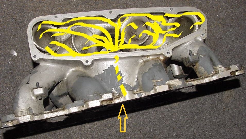
Air flowing through dog-legs etc wants to take the shortest path, shown by the red area on the inside of the turn.
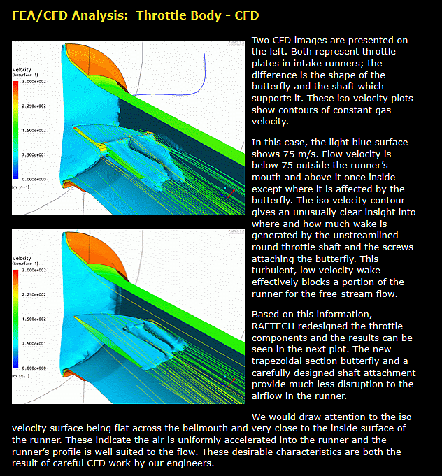
This brings it across the face of the partly opened butterfly plate, resulting in a turbulence shadow, or wake.
The best flow occurs when the plate is at about 45 deg, ie parallel to the airflow.
Beyond that, it goes back to the air flowing obliquely across the plate, again leaving a turbulence shadow.
To alleviate this, many manifolds incorporate turning vanes, or splitters, to separate flow cleanly to each side on the butterfly throttle plate.
Took a look at your rendering. That's a good design, in my opinion. The plenum roof is high enough that you have a lot of options for designing a lower plenum that distributes well. The plenum volume doesn't matter in terms of tuning for this kind of manifold, which gives you a lot of freedom. If your throttle body stays at the currently modeled location, there's going to be some careful thinking needed to feed the two back cylinders as well as the rest. If you make a flat box plenum and feed it with a pipe from the center, you're guaranteed to get the distribution correct. But it's not the simplest design to fabricate, in my opinion. A lot of work left, but progress is impressive.
You're aware this isn't a "start from scratch" design exercise, but a production version of an already designed and tested manifold, right?
Thanks to Hans�s pictures it looks not to be very difficult to fabricate the intake. I like metalwork and I am in the possession of a complete workshop. However I will refrain in favour of my own design or Mr. Brown will call me a copy cat.
The intake gained a good 50 rwhp on Rob Edward GTS stroker, not bad. Post #183 https://rennlist.com/forums/928-foru...udy-hp-13.html
�ke
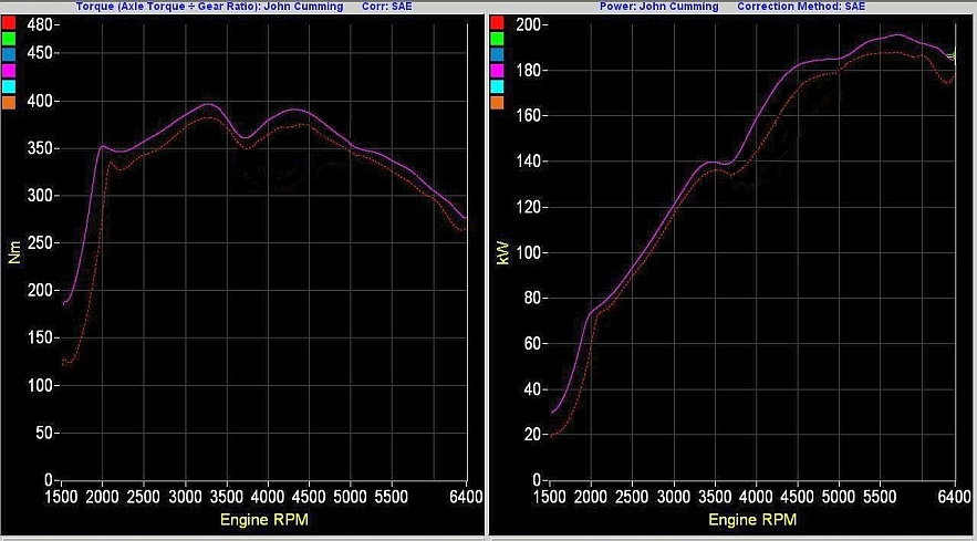
I obviously don't need to make excuses for the gains we achieved on the engines we tested this manifold on.....it worked well.
Howevet, it is worth noting that this prototype manifold was hampered by the plenum fabrication. What started out as smooth pieces with good airflow ended up being a cobbled up mess, because of different factors. While the significantly disturbed airflow was insignificant at lower engine speeds, the very disturbed air became a major issue as the rpms went up.
The production version will work much better, in the higher rpm range.
My goal is a 75 horsepower gain on these 6.5 liter engines, without trading torque for that horsepower. And on the 5.9 liter versions, I'm looking for a true 500+ flywheel horsepower.
You're aware this isn't a "start from scratch" design exercise, but a production version of an already designed and tested manifold, right?
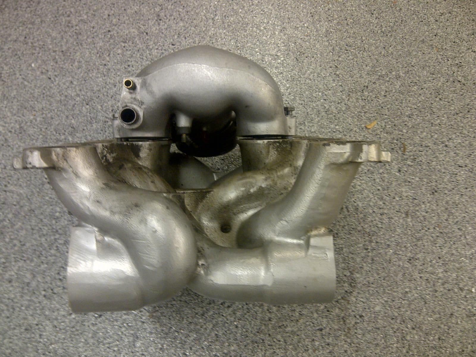
What Hans has drawn there is very similar in appearance to your prototype manifold. It's also similar to Porsche's "Group B" S3 manifold. And a countless number of other EFI intake manifolds made over the last 30 years, including GM and Ford manifolds, Nissan Titan manifold etc. Curved runners going into a central plenum fed thru a single throttle body is a very old and commonly used design. Surely you don't disagree?
Whether what Hans has drawn is similar to your prototype intake depends on a list of design parameters that distinguish between all the various V8 manifolds with curved runners with a single throttle body plenum in the valley. Most importantly, the runner length and diameter. Slightly behind those in terms of importance, the curvature tables of the runners and the vertical level of the plenum roof plane. If those parameters are the same, or very close then I'd say that what Hans has drawn could be considered a production version of your prototype manifold. I don't know those parameters for your intake, so I can't really opine on the similarity or the two in one direction or another.
If you and Hans are building these manifolds together, that seems like a good thing to me. With complementary skills and the knowledge already accumulated from your prototype intake manifold, by my guess your cooperation is going to make it more likely that these manifolds will be available sooner. And I think -- and this is just a personal opinion -- the manifold will be a very good one for a normally aspirated car with a manual transmission, based on what I've seen.
My goal is a 75 horsepower gain on these 6.5 liter engines, without trading torque for that horsepower
If you are speaking of the peak torque, this manifold will in my opinion and prediction produce a ton of it compared to the stock S4 intake. At low rpms, however, the stock S4 intake manifold is hard to beat for torque production, making it in my opinion a very good manifold for automatic cars. But for manual transmission (normally aspirated) cars, the stock S4 intake is in my opinion an unnecessary compromise and a single plenum manifold with straight and long runners will be better. These are all my personal opinions.
For a turbo street car, you kind of want to go into either corner solution. Either a big turbine and manifold with most torque at low rpms before the turbine spools or a smaller turbine and a short-runner stub intake that will help at the very top end. In either case, the turbo can fill in any torque curve hole in the mid range rpms. I understand that this is turbo case is a total niche case with about 10 turbo 928s out there, so it of course should have approximately zero influence on any commercial 928 intake manifold production effort. Just bringing this up here to explain why my interests on these manifold topics are somewhat orthogonal to almost everyone else's interests.
The gains on the engines we tested this manifold on were hampered by the plenum fabrication. What started out as smooth pieces with good airflow ended up being a cobbled up mess, because of different factors. While the disturbed airflow was insignificant at lower engine speeds, the very disturbed air became a major issue as the rpms went up.
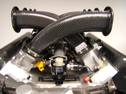
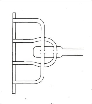
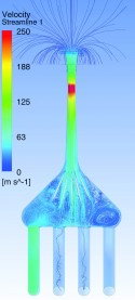
In case you and/or Hans are interested in my unsolicited opinions, here is one idea that might be worth considering in terms of feeding the plenum. First, make a relatively shallow box plenum that is maybe 3 inches deep and has the other dimension equal to the rectangle roof plate in Hans's rendering. This is by my understanding similar to the flat plenum of the S3 Group B plenum, the understanding being limited because of I've just seen one photo of it. Then, feed that plenum with a conical distribution manifold that has the throttle body attached to it. The conical distribution manifold and its narrow feed slot would be centered better and approximately the length of the block valley, but really the slot can start between the cylinders 1&5 and 2&6 and end between 3&7 and 4&8. This kind of distribution manifold is pretty much guaranteed to produce equal air distribution to the runner inlets. I don't know if the space constraints allow for this, though.
What I'm thinking about is this kind of feeder plenum, with the main plenum of course much wider and flatter than what is in the below picture:
What Hans has drawn there is very similar in appearance to your prototype manifold. It's also similar to Porsche's "Group B" S3 manifold. And a countless number of other EFI intake manifolds made over the last 30 years, including GM and Ford manifolds, Nissan Titan manifold etc. Curved runners going into a central plenum fed thru a single throttle body is a very old and commonly used design. Surely you don't disagree?
Whether what Hans has drawn is similar to your prototype intake depends on a list of design parameters that distinguish between all the various V8 manifolds with curved runners with a single throttle body plenum in the valley. Most importantly, the runner length and diameter. Slightly behind those in terms of importance, the curvature tables of the runners and the vertical level of the plenum roof plane. If those parameters are the same, or very close then I'd say that what Hans has drawn could be considered a production version of your prototype manifold. I don't know those parameters for your intake, so I can't really opine on the similarity or the two in one direction or another.
If you and Hans are building these manifolds together, that seems like a good thing to me. With complementary skills and the knowledge already accumulated from your prototype intake manifold, by my guess your cooperation is going to make it more likely that these manifolds will be available sooner. And I think -- and this is just a personal opinion -- the manifold will be a very good one for a normally aspirated car with a manual transmission, based on what I've seen.
One of the very first things that becomes extremely evident, when first starting out designing a manifold, is that there are very limited ways to "package" an intake system and have "proper" runner lengths.
So, it is no shock that my ending manifold design is similar to other modern V8 manifold designs....
[QUOTE=ptuomov;13206683]What Hans has drawn there is very similar in appearance to your prototype manifold. It's also similar to Porsche's "Group B" S3 manifold. And a countless number of other EFI intake manifolds made over the last 30 years, including GM and Ford manifolds, Nissan Titan manifold etc. Curved runners going into a central plenum fed thru a single throttle body is a very old and commonly used design. Surely you don't disagree?
Yes, similar designed intake manifolds can be seen on many V8 engines like my wife�s BMW Alpina B10 4.6. A very smooth engine putting out 350 hp and much low end torque.
�ke
In case you and/or Hans are interested in my unsolicited opinions, here is one idea that might be worth considering in terms of feeding the plenum. First, make a relatively shallow box plenum that is maybe 3 inches deep and has the other dimension equal to the rectangle roof plate in Hans's rendering. This is by my understanding similar to the flat plenum of the S3 Group B plenum, the understanding being limited because of I've just seen one photo of it. Then, feed that plenum with a conical distribution manifold that has the throttle body attached to it. The conical distribution manifold and its narrow feed slot would be centered better and approximately the length of the block valley, but really the slot can start between the cylinders 1&5 and 2&6 and end between 3&7 and 4&8. This kind of distribution manifold is pretty much guaranteed to produce equal air distribution to the runner inlets. I don't know if the space constraints allow for this, though.
What I'm thinking about is this kind of feeder plenum, with the main plenum of course much wider and flatter than what is in the below picture:
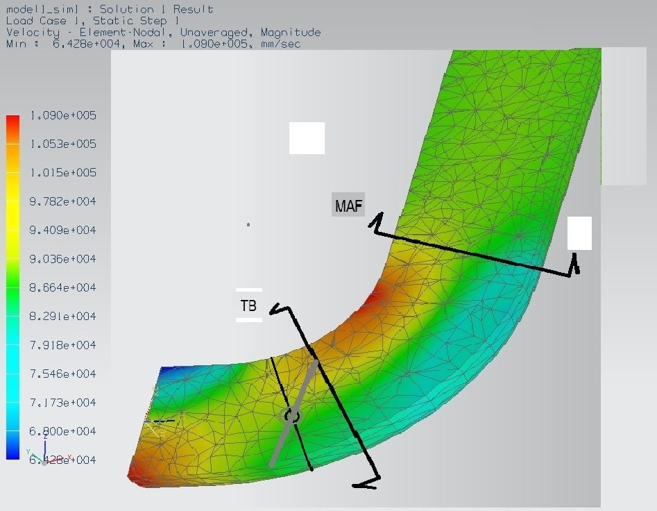
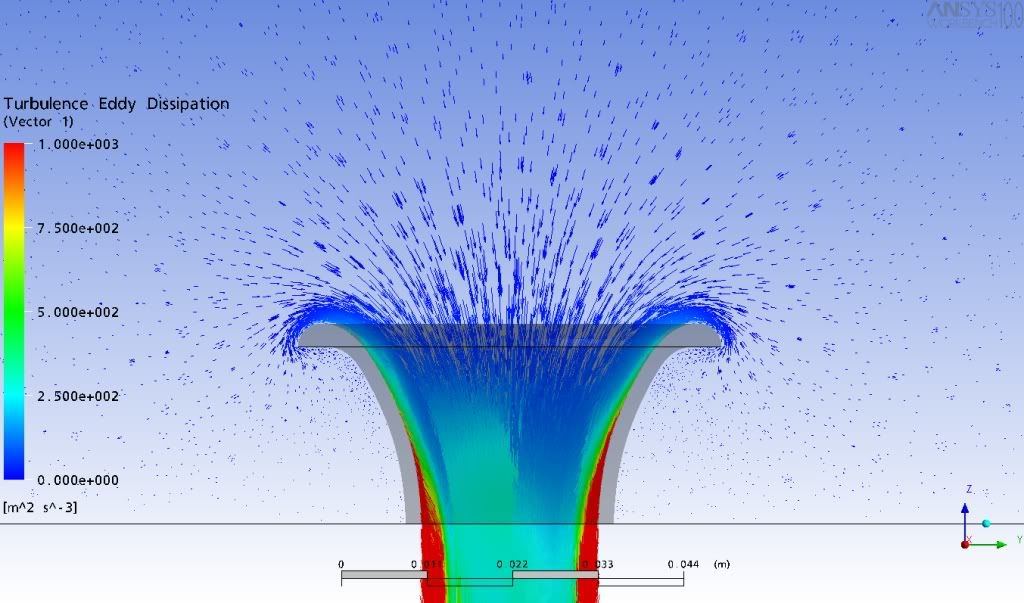
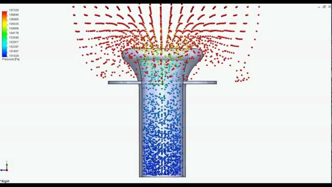
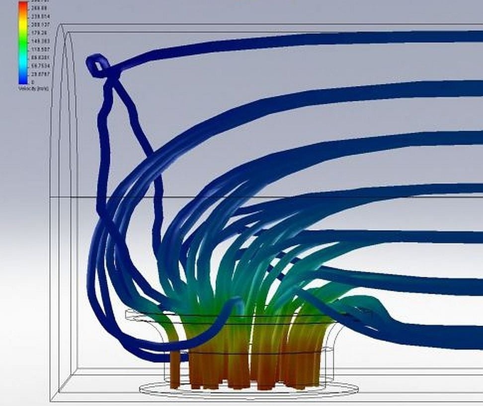
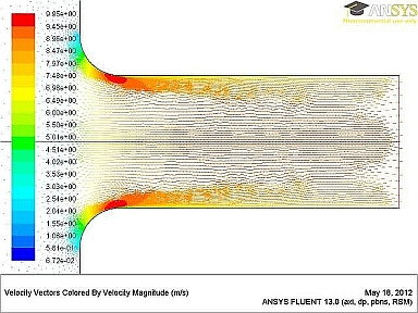
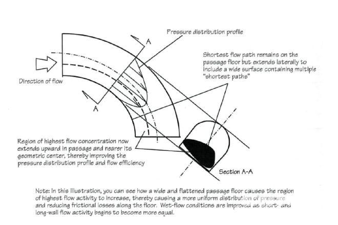
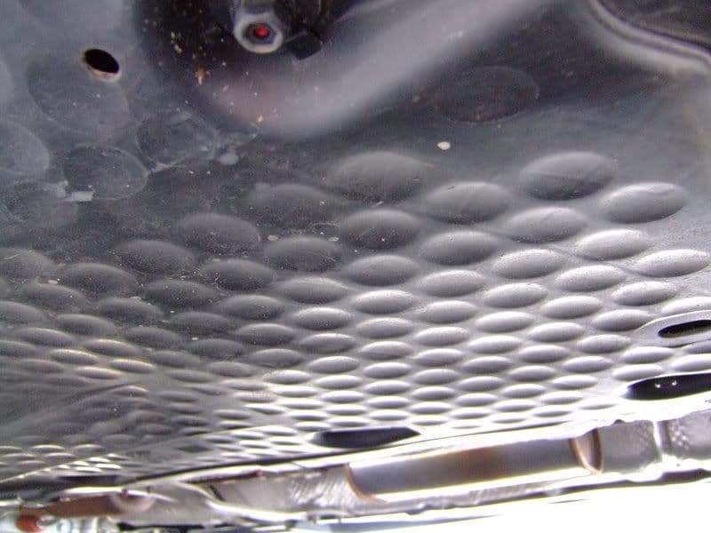
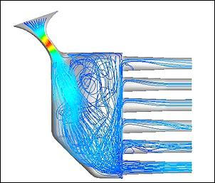
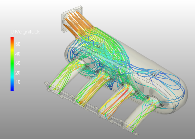
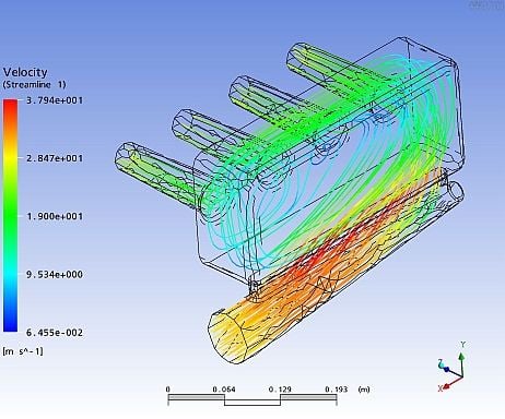
======================================================================== =============== There's more to feeding intakes from a plenum than a "looks about right approach".
Examine these computer emulations: the aim is (obviously) for even flows across all runners.
If one simply looked at them, their appearance would certainly impress, until the airflow's were measured.
Last edited by UpFixenDerPorsche; 04-20-2016 at 08:15 PM.

 04-16-2016, 03:40 PM