When you click on links to various merchants on this site and make a purchase, this can result in this site earning a commission. Affiliate programs and affiliations include, but are not limited to, the eBay Partner Network.
that was along the lines i was thinking, but i do think the stock fuel rails would work as well as the RRFR i have and dampers. if we needed to change to Hans' fuel rails, sure, why not. i dont think there is an issue with pulsation as i have shown with my experience that not to be a problem at all at fuel pressures up to 75ps on 19lb injectors to 40psi on 30lb injectors using the stock stuff.
we also dont need to worry about he cross member or oil filler, as the AM intake would be pointed rearward. that way, we use the air below the base of the windshield and there is a tone of room there for filter and MAF. worst case, a simple extension wire loom for the MAF, like mark and joe had. the only real challenge will be plumbing in the idle stabilization , and the breather lines will be a breeze as you can imagine.
My goal is to use the stock stuff and only gain the 50hp on the 6.5 liter or the 30hp on the S4. not too lofty goals. and i bet it can make more. If i was to consider a MAP or other engine management, heck, i would just go ITB and call it a day! .. maybe thats the way! the entire project is wrapped around bolt on HP with no changes. I think its more than possible for the AM intake,but it will take mastery of welding and fitting to make it work... i agree!
Originally Posted by dr bob
Mark--
Take a hard look at the A-M manifold, and consider cutting the runners off just below the floor of the plenum, all in one plane. Leave enough "stub" sticking out to support a pair of flat flanges. Have the flanges welded to the intake, then cut flat after welding. A second mating flange for each side, identical to the one you welded to the plenum but with bores to match the A-M runners, will be the top plate on your adapter, with grooves on the mating faces for o-rings of course.
From that point, your task is to figure out how to get from the plate you made with the A-M runner openings to Hans' mounting flanges for the 928 heads. Your fabricator can do the initial fit-up and tack things while assembled, then unbolt the pieces from the heads and the plenum for full access and finish welding (or gluing...).
You are obviously space-constrained vertically by the water bridge, the hood, the crossbar, and the floor of the valley. Remember all the stuff that "lives" under the intake, including the oil vent hoses, idle air controller and such. You'll need to figure out how to plumb all that stuff in the available space.
Hans has the fuel rails that fit on his flanges and use available injectors and seals, so you won't need to engineer at least that part of the fuel system. But you will need to work out the pumps and dampers, the return system and a fuel cooler to work well with the batch-fire injection. Or move to another engine management package with sequential-fired injection, so you don't have the hard pressure waves that come with opening and closing all eight injectors as one.
You will want to add EGT probes to individual exhaust runners, connected to your data-logger, and at least one more oxy sensor to guide you as you work to balance the effects of uneven airflow to the cylinders. Another reason to upgrade the engine management. Dump the MAF system for MAP and charge temp system, and one less component to try and fit up on the air side. You'll need to locate and mount/adapt a throttle body big enough for your stroker at full song. And the rest of the air intake plumbing/filters/linkages/etc.
Once you have the runner "adapters" made, you can move on to a plenum box with the same flange setup, and the ability to fab and fit different horns inside for different-sized engines and different uses. Makes it a marketable "fitzall" intake, really. Plus all that other stuff...
As you note above, Bob, there's really nothing to this new intake stuff. I'm shocked that will all the conversations about how poorly the stock intake works, for so many years, that no one has stepped up, invested the 75K+ to produce a "short" run of manifolds....like I'm doing.
And if you think I'm shocked....you should hear my wife talk about it. "Another in a long line of 928 pieces that you will never sell enough of to make up for the time or money spent developing it."
My favorite saying: "I loose money on everything I build and sell, but I make it up in volume."
Someone pointed out, last week, that what I do has to be a hobby, because it makes zero business sense.
And there are a great many of us who are very happy you are doing so, because you are doing things no one else has the time, money, or patience.. So thank you.
As you note above, Bob, there's really nothing to this new intake stuff. I'm shocked that will all the conversations about how poorly the stock intake works, for so many years, that no one has stepped up, invested the 75K+ to produce a "short" run of manifolds....like I'm doing.
And if you think I'm shocked....you should hear my wife talk about it. "Another in a long line of 928 pieces that you will never sell enough of to make up for the time or money spent developing it."
My favorite saying: "I loose money on everything I build and sell, but I make it up in volume."
Someone pointed out, last week, that what I do has to be a hobby, because it makes zero business sense.
I just added up the money ive made racing cars for 20 years.....wooops! dont tell my mom!
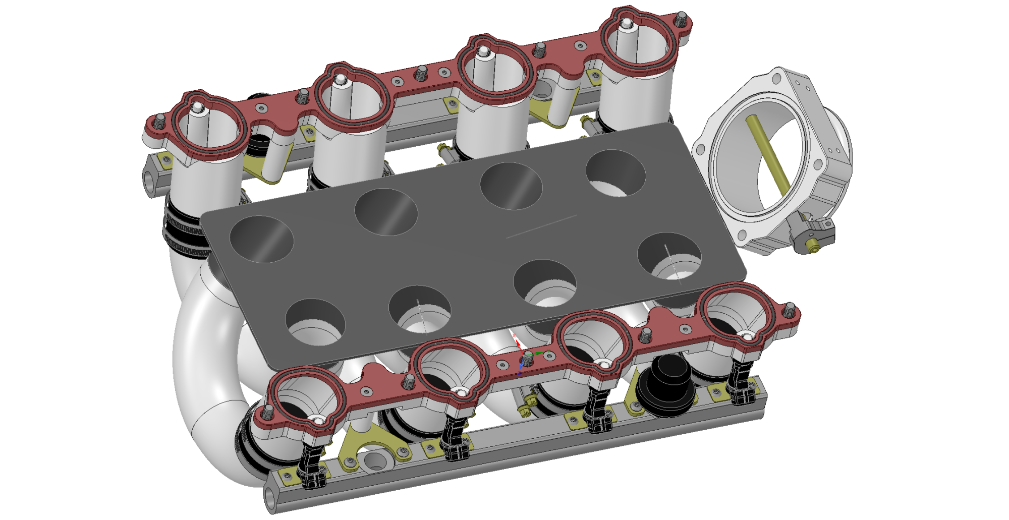
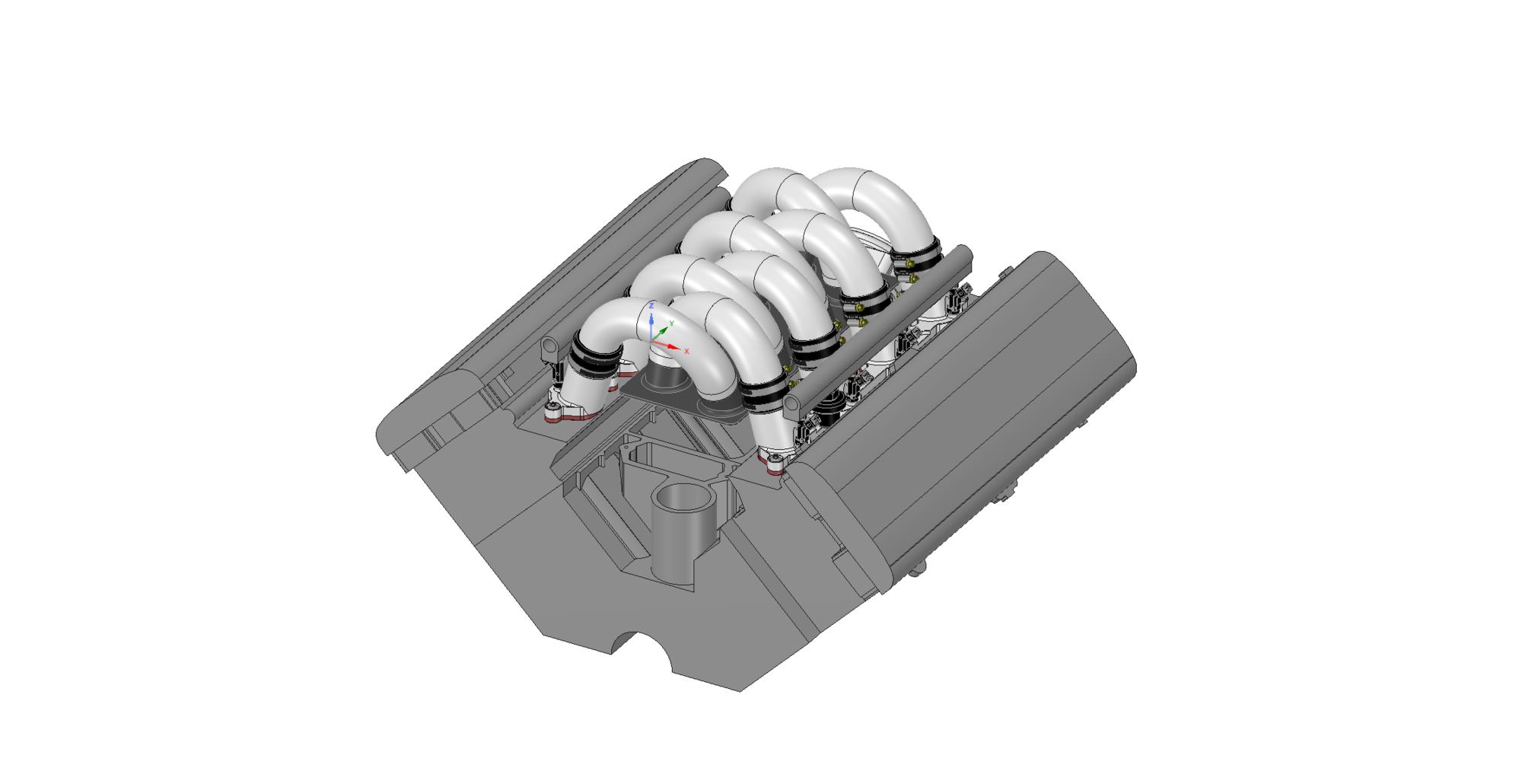
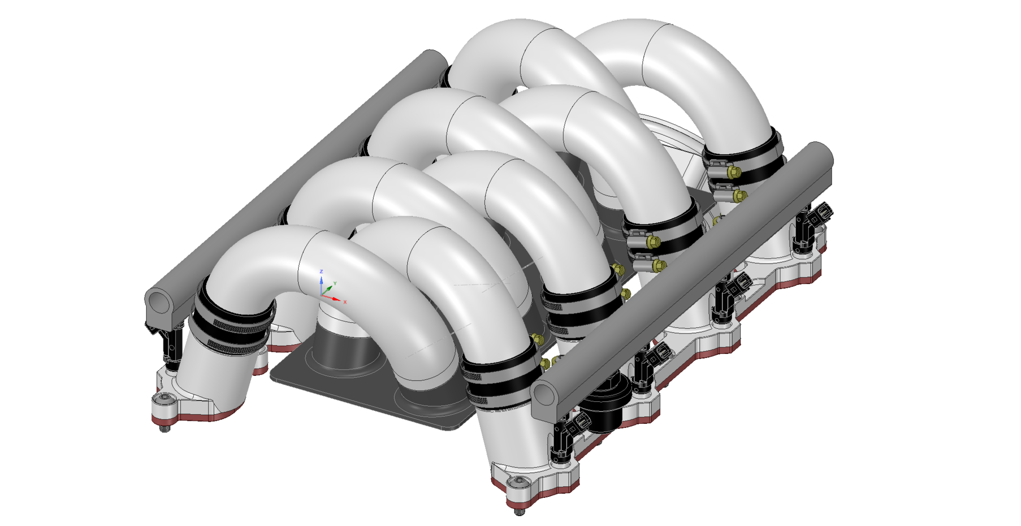
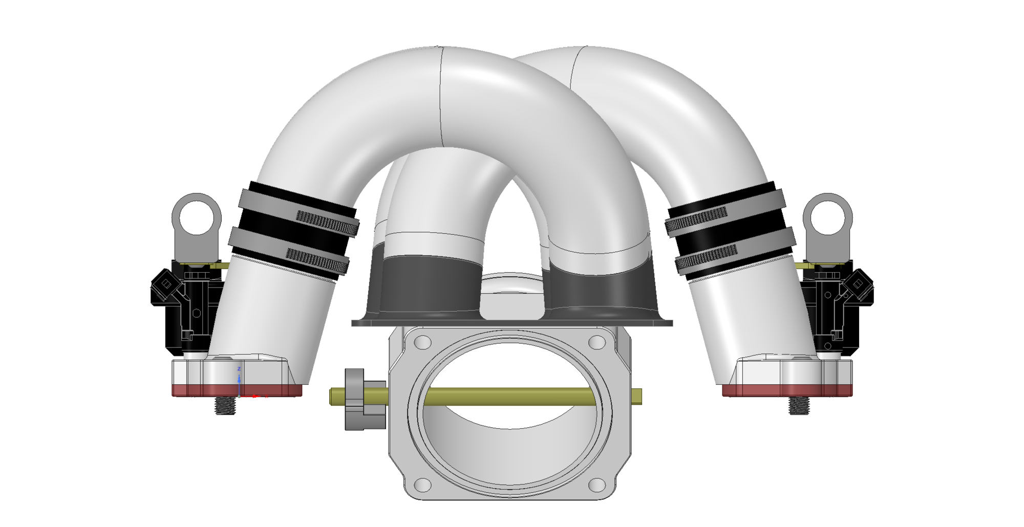
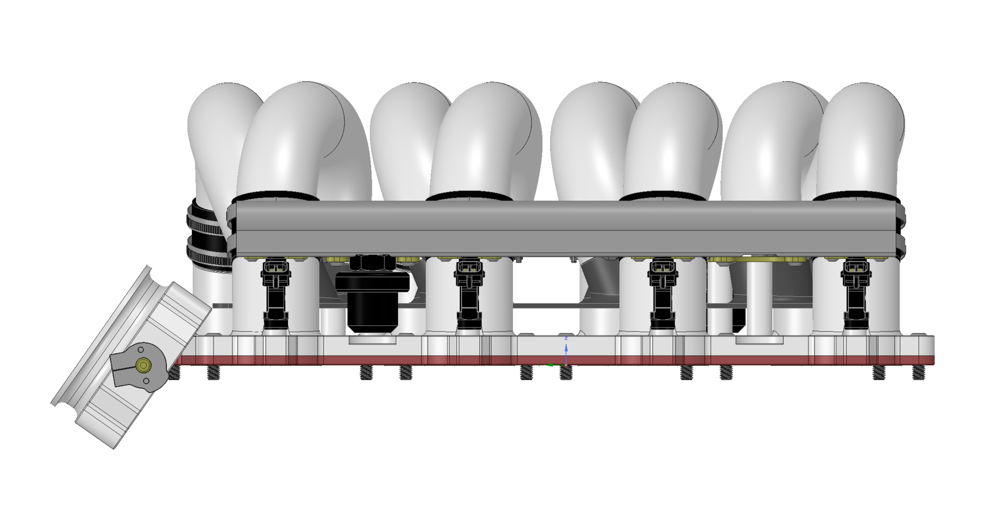
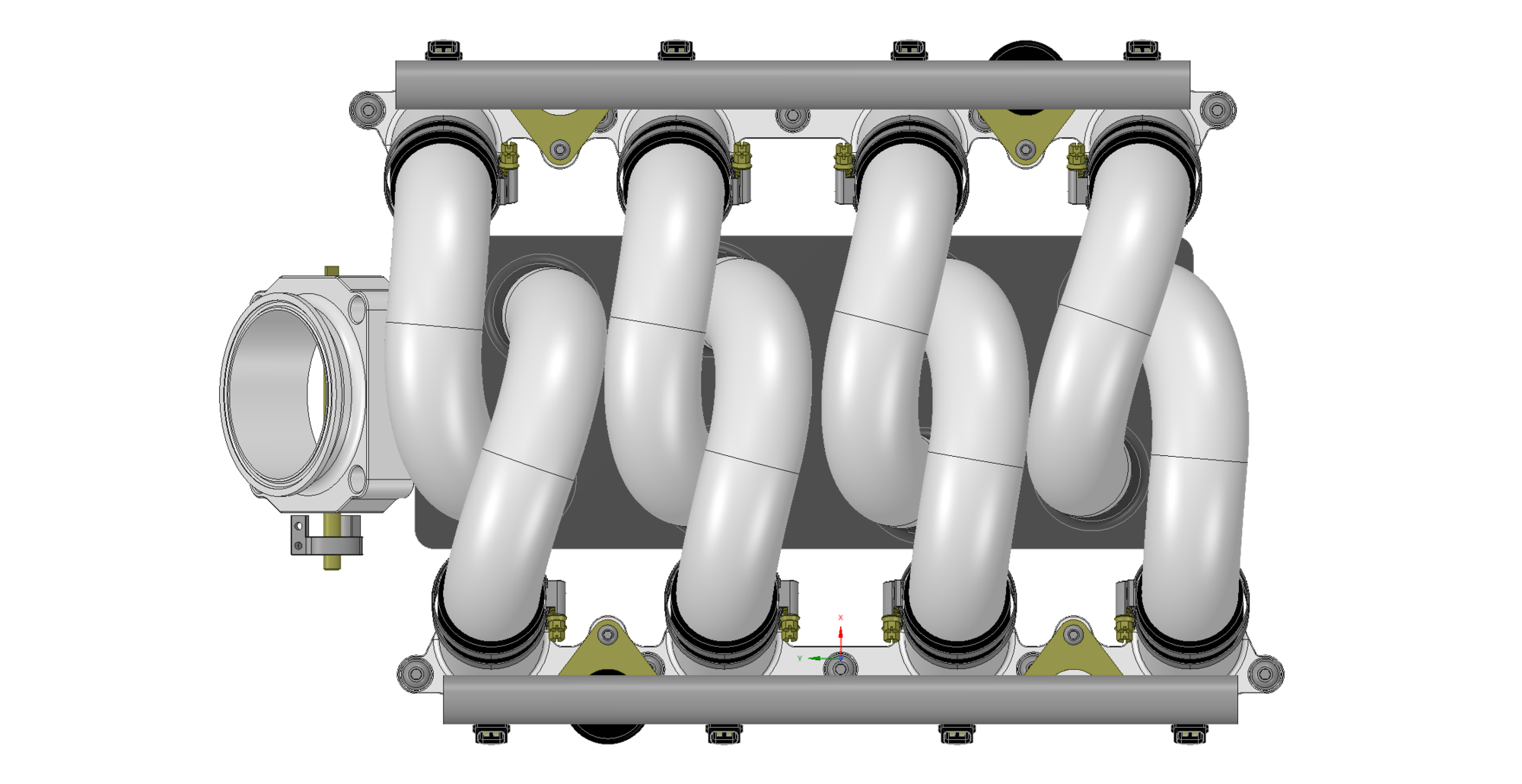
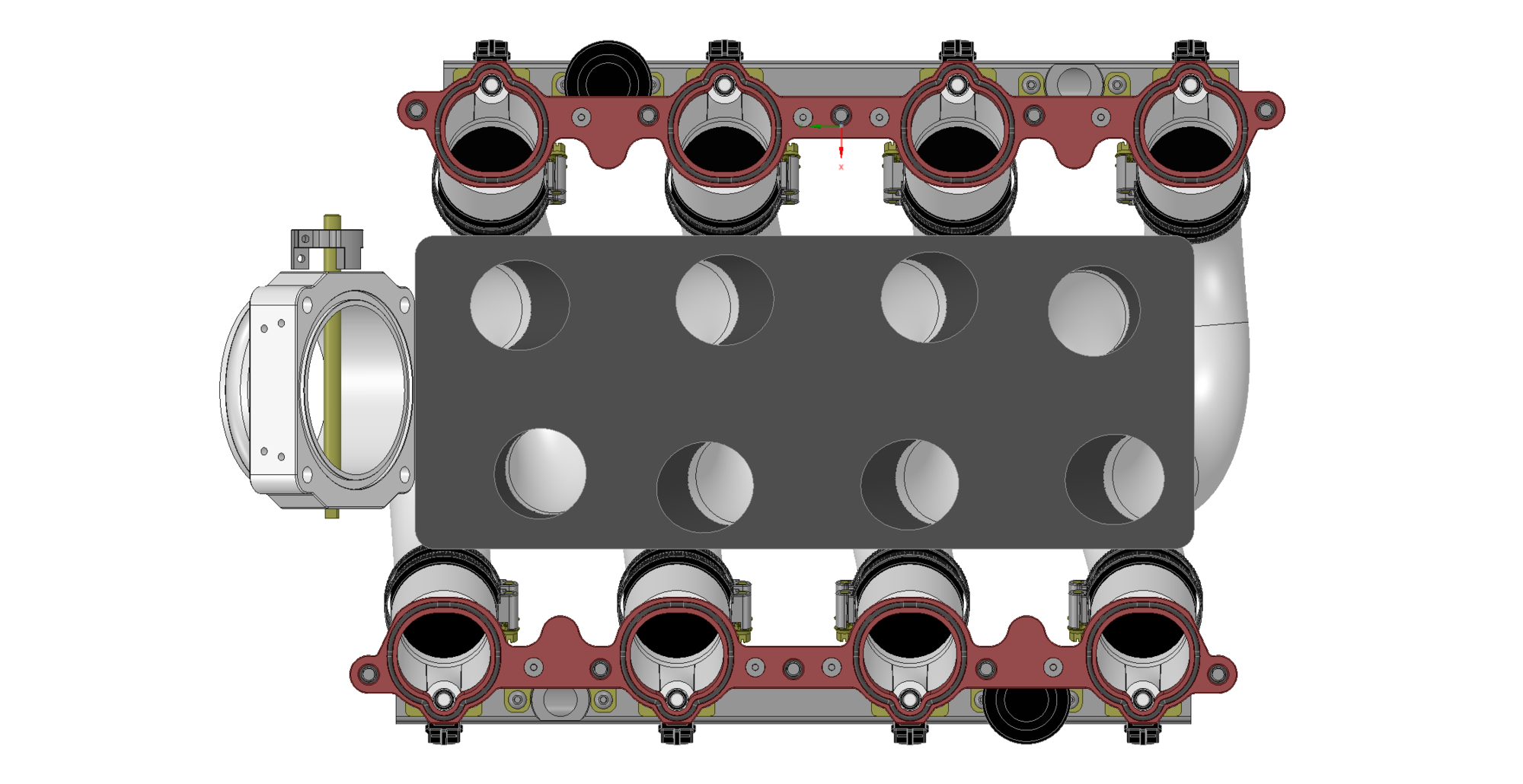
In an attempt to steer this back somewhat close to the tracks, I figured we should probably post something to show the progress. The lowers have been designed, tested via 3d printer, and should be ready at the machine shop any day. Runners have been calculated, they should clear the hood for anyone running stock or similar height mounts. Upper plenum has been designed, but will be modified according to the lower design. The lower cant be modeled until I have some time to play with the throttle location to make sure we can get the Y-pipe to clear the fuel cooler and all the other stuff by the firewall. I hope to get that done this weekend, but its already pretty full.
There are some interesting features already incorporated in this design, such as a Garolite spacer at the heads to minimize heat transfer and integrated dampers in the fuel rails.
Its getting darn close, but still some things to figure out, such as throttle actuation, throttle location, tps adapters... but those should all come pretty quickly after the lower plenum design.
For those sketching out their own design, I will note that there have been MANY iterations of this design over the past couple months. There are actually four separate bend tables for the runners although they look similar. Its not rocket science to design this stuff, but it does take a lot of dedication and a time and financial commitment.
So, here are some captures from CAD as well as a fully manipulable 3D model for your consideration:
I absolutely love his comment "I will note that there have been MANY iterations of this design over the past couple months."
Master of understatement.
At one point in time, I was worried he was going to quit....
Did I mention that Hans is talented?
awesome!!!!! reallly!
so, this is your design team greg?
can i ask the question, How much for intake if i run all the stock stuff bolting to the system at the TB. you can PM me if that has not been determined or want to give me a ball park.
How much for intake if i run all the stock stuff bolting to the system at the TB. you can PM me if that has not been determined or want to give me a ball park.
Mark, So are we to understand by your comments that you want to pay for all the design and revisions up to this point and have a one-off intake produced for just you?
Somehow I just don't think this you quite realize the work involved leading to this point right here and now.
But if you are now opening up your wallet at this point, Kudos to you!!
If greg needs the margin for all the other components to make it all work. i get it, but i dont want a 1 off, i want just the intake and a platform to make all the stock stuff work. i think this would help him "make it up in volume" if it worked. if it didnt, well what did he loose? nothing as i would have to step up and buy the rest. i'm convinced the stock EFI components will work as they have on others with similar HP output. we do know mark and Joe had near 420rwhp with the stock manifold... this i have the dyno runs from!
awesome!!!!! reallly!
so, this is your design team greg?
can i ask the question, How much for intake if i run all the stock stuff bolting to the system at the TB. you can PM me if that has not been determined or want to give me a ball park.
I determined that if I took the prototype, refined it, and them hand made it, the price would have been 15K+.
Hans is putting my ideas (and his) into digital form, so that I can have these made for reasonable amounts of money. To be able to have them made (for reasonable amounts of money), I'm going to have six complete manifolds made, initially.
I can't determine the price, until all of the individual pieces are done.
However, my "target" price was $7500. It will be interesting to see if we can do that.
if you can do that Im interested! im in especially if it can be a little lower using the stock stuff.
let me know if you need a C and C shop close by your shop . One of my best friends owns it and does aircraft/NASA small projects . He might be able to take on the Hans' base's. if you want to have me quote it out, you can send me the cad drawings and an NDA and we can investigate lowering the costs of some components.
In an attempt to steer this back somewhat close to the tracks, I figured we should probably post something to show the progress. The lowers have been designed, tested via 3d printer, and should be ready at the machine shop any day. Runners have been calculated, they should clear the hood for anyone running stock or similar height mounts. Upper plenum has been designed, but will be modified according to the lower design. The lower cant be modeled until I have some time to play with the throttle location to make sure we can get the Y-pipe to clear the fuel cooler and all the other stuff by the firewall. I hope to get that done this weekend, but its already pretty full.
There are some interesting features already incorporated in this design, such as a Garolite spacer at the heads to minimize heat transfer and integrated dampers in the fuel rails.
Its getting darn close, but still some things to figure out, such as throttle actuation, throttle location, tps adapters... but those should all come pretty quickly after the lower plenum design.
For those sketching out their own design, I will note that there have been MANY iterations of this design over the past couple months. There are actually four separate bend tables for the runners although they look similar. Its not rocket science to design this stuff, but it does take a lot of dedication and a time and financial commitment.
So, here are some captures from CAD as well as a fully manipulable 3D model for your consideration:

 04-15-2016, 03:48 PM
 the entire project is wrapped around bolt on HP with no changes. I think its more than possible for the AM intake,but it will take mastery of welding and fitting to make it work... i agree!


 if it worked. if it didnt, well what did he loose? nothing as i would have to step up and buy the rest. i'm convinced the stock EFI components will work as they have on others with similar HP output. we do know mark and Joe had near 420rwhp with the stock manifold... this i have the dyno runs from!