When you click on links to various merchants on this site and make a purchase, this can result in this site earning a commission. Affiliate programs and affiliations include, but are not limited to, the eBay Partner Network.
There are many ways to feed a plenum. Without much experience in this, my opinion is that the simpler the fabrication effort and more compact the design, the harder it is to get the air distribution correct.
For many such compact designs, one has to experiment a lot, either in real world or in the simulation world. Otherwise the distribution sucks.
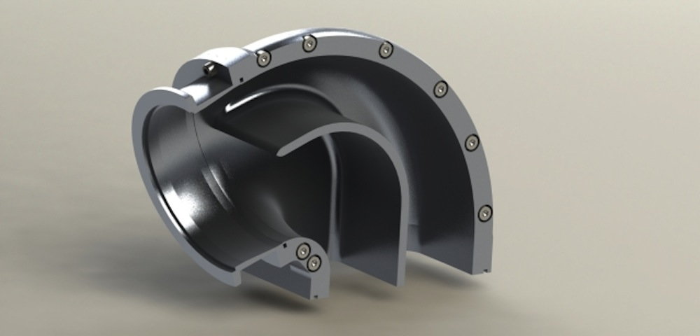
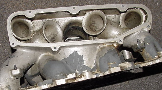
There are, however, a couple of fool proof ways to feed a plenum from the distribution perspective. They aren't the cheapest to fabricate or the most space efficient, but they rarely fail. It is my understanding that the so called "Lehmann" design is such a foolproof design, even paying proper respect to the ingenuity of fools. Bottom feeding at the center of the plenum is another such design, used by Porsche in 928 16V models.
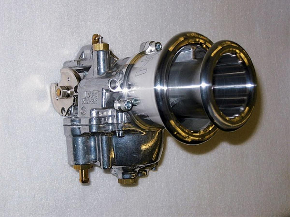
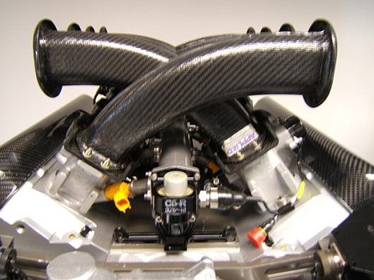
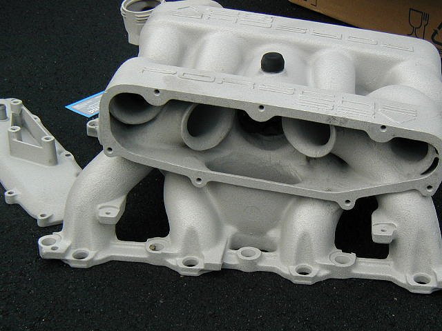
Perhaps disappointing some of the readers, I am not going to insert all of my photos of the Lehmann conical dual plenum manifold into this post. I am only going to include a link to a google search here that will take you to such images:https://www.google.com/search?q=lehm...lenum+manifold. I understand this is a real letdown for many...
The stock regulator works pretty well with a single 044 pump, in my experience. The fuel heats up, but not enough to cavitate the pump. AFR will go a bit lean though when the tank is low.
Are you using the stock pump or 044 pump? Because the flow rate is very different.
Also one question is what level of a problem would register on your radar screen?
I may have forgotten, but I run the stock S4 pump which I thought is the 044 version, correct?
AFR never goes lean, I moniter it all ways and have calibrated the AFR sytem with the wide band at the dyno. it never varies at the track, and I always (90%) run the car to the reserve light every qual or race session.
if it was to run near 13:1, It would show up on the AFR lights.
Interesting that Bosch prescribed a higher-pressure pump to try and solve fuel heating problems on early CIS cars. That helped with boiling in the rails but exacerbated the total heating problem... Which ultimately made boiling worse in the lines. The fuel coolers in the 928 are there for a reason.
I haven't seen any issues and have been in 100s of races now, most all with a caution mid race with no issues at all.
if the lines are at 50psi or 75psi as they were on the Holbert S4, do you know what the boiling point is for gasoline? I have a hard time believing that there is that much heating going , having played with a hot engine and have drained fuel from the tank and it wasn't even warm after practice as I wanted to take some fuel out before qualifying from quarter tank to 1/8 tank.
Originally Posted by UpFixenDerPorsche
I'll be back soon to complete explanations, but for the moment many image sets are reasonably self explanatory.
Cheers
Upfixen
You hit the nail on the head Strosec, , and, might I say, seem the only Rennlister who has shown this level of understanding of the airflow problems.
Everyone else is capable of amazing machine work, but with airflow they're stabbing in the dark, and with moving air you just can't do that.
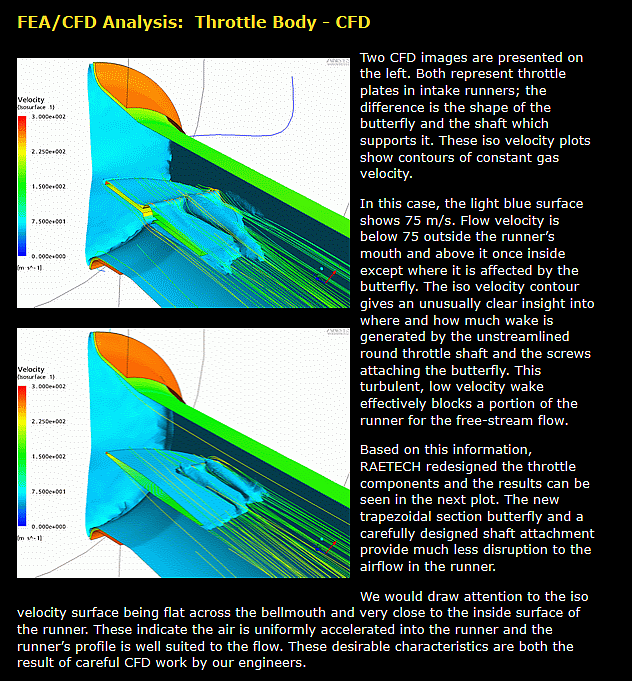
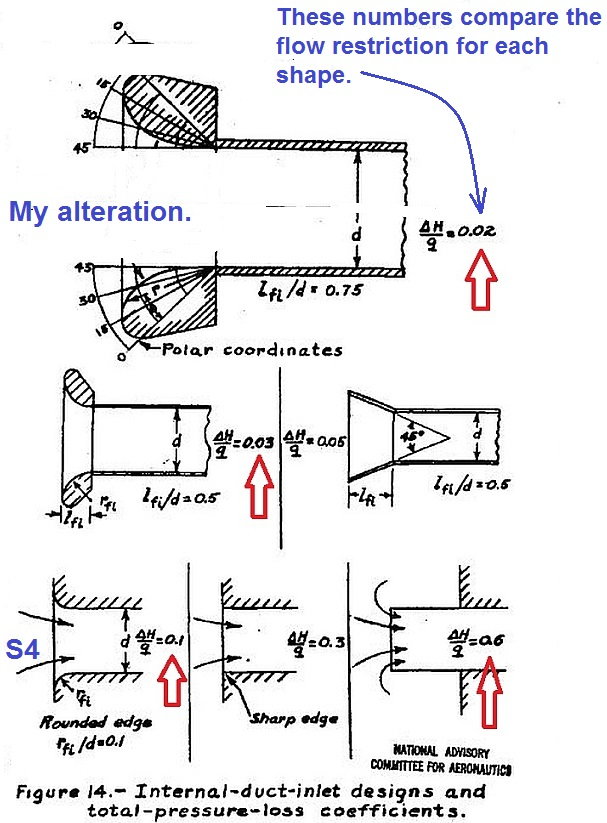
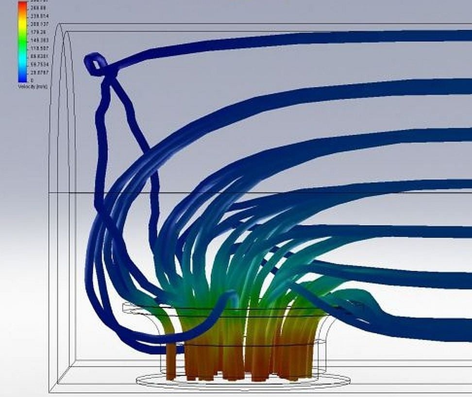
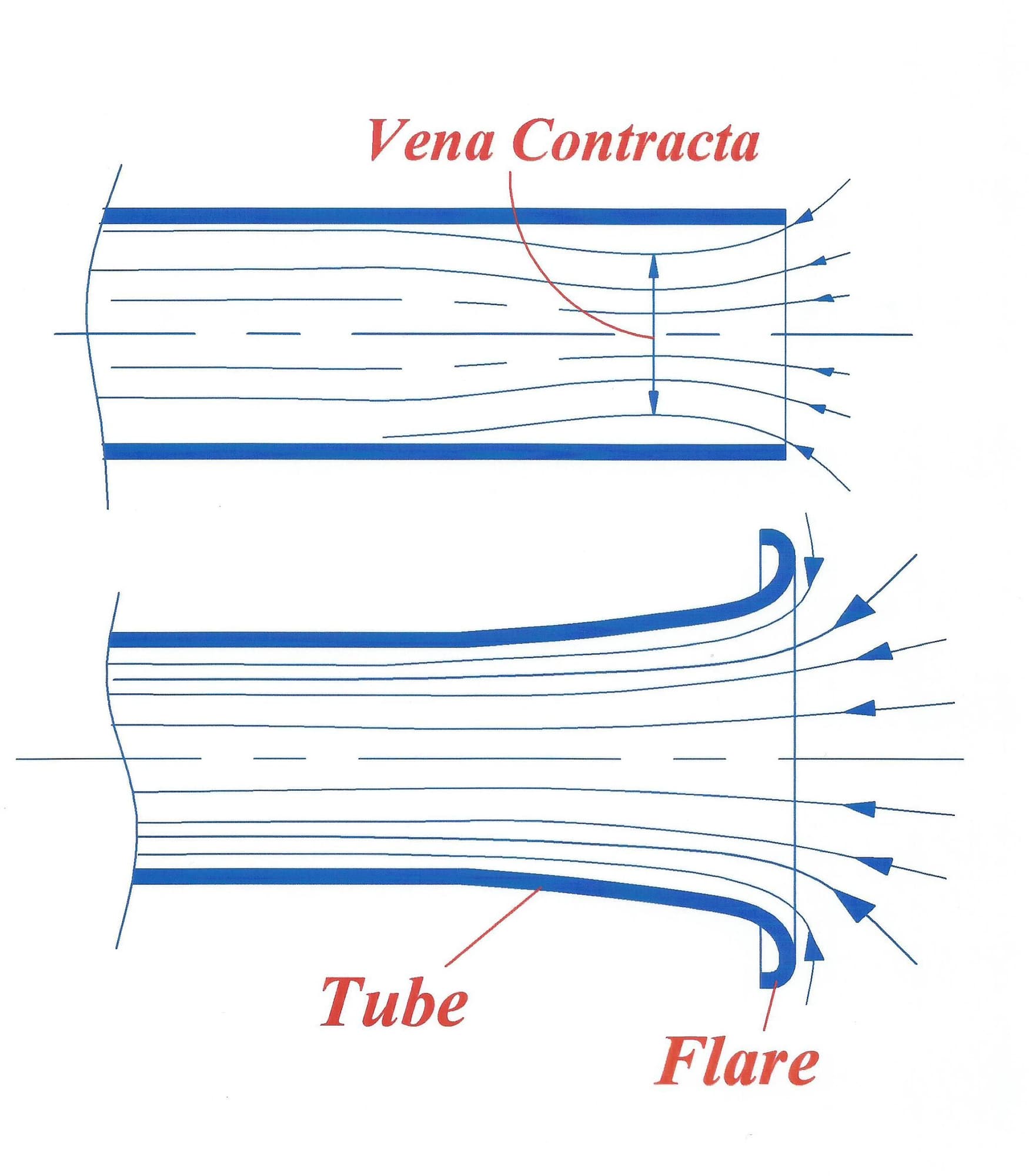
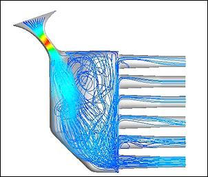
Below I've posted a spread of stuff out my "aero" library. It shows the why's and wherefore's behind my intake manifold performance gains, and the subtleties of airflow behaviour.
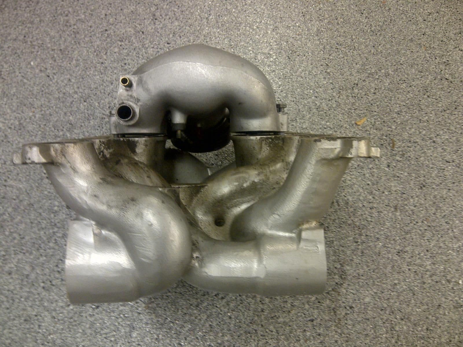
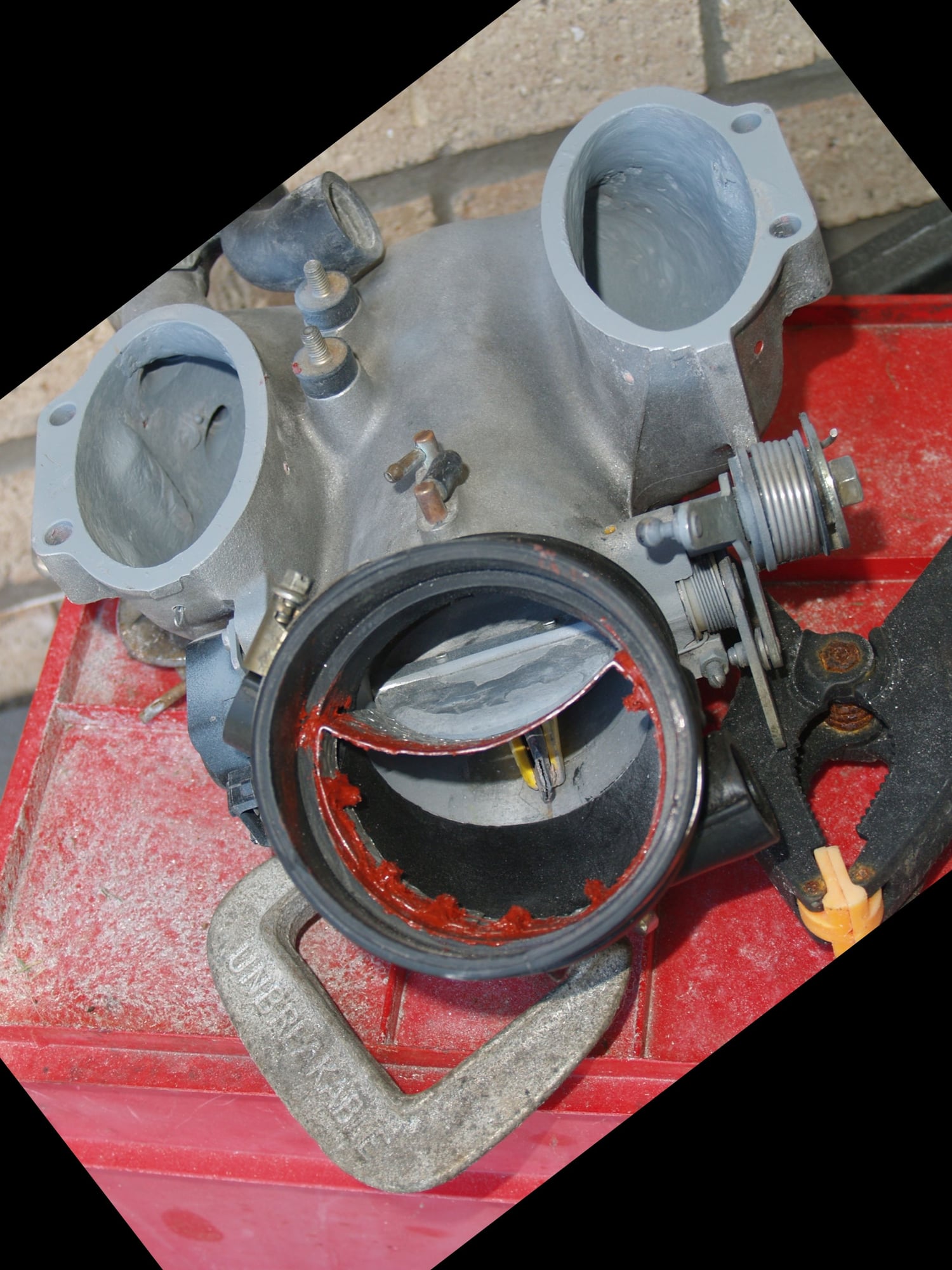
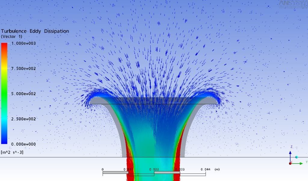
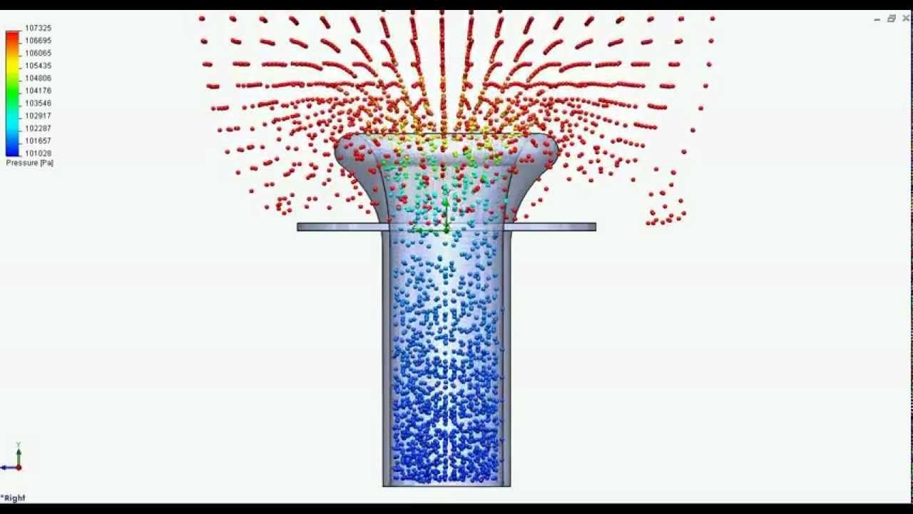
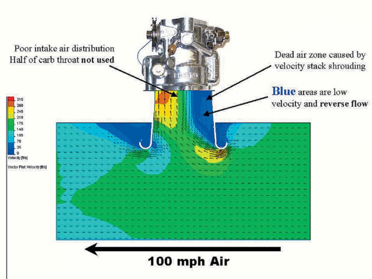
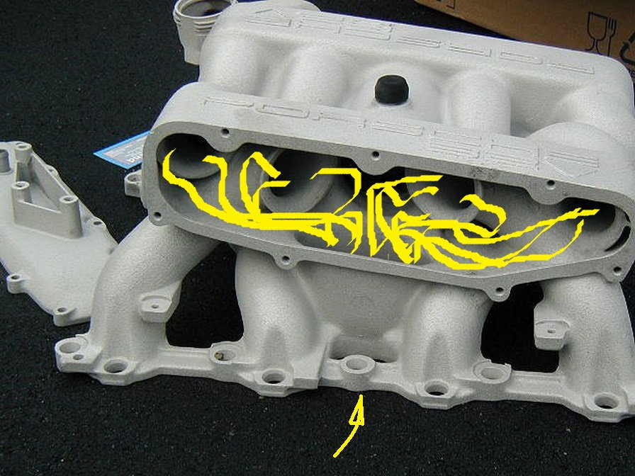
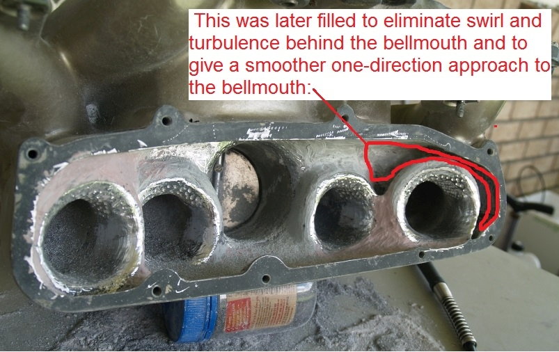
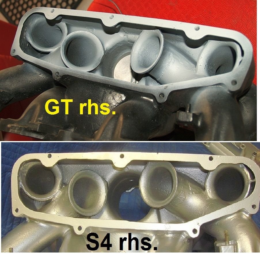
Intake air pathway on 928 S4:
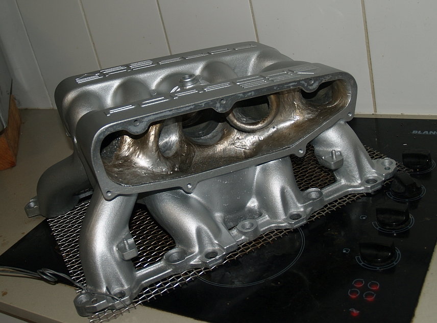
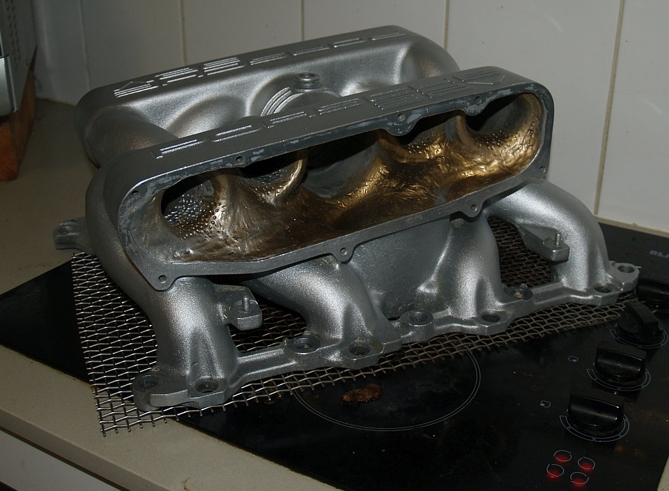
An understanding (and application) of this was at the core of my S4 intake manifold modifications.
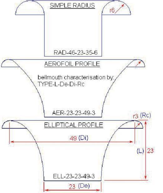
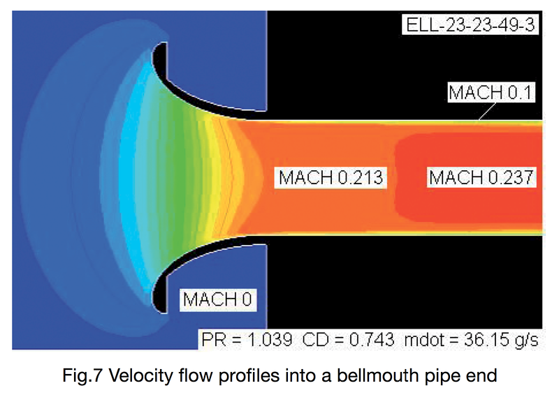
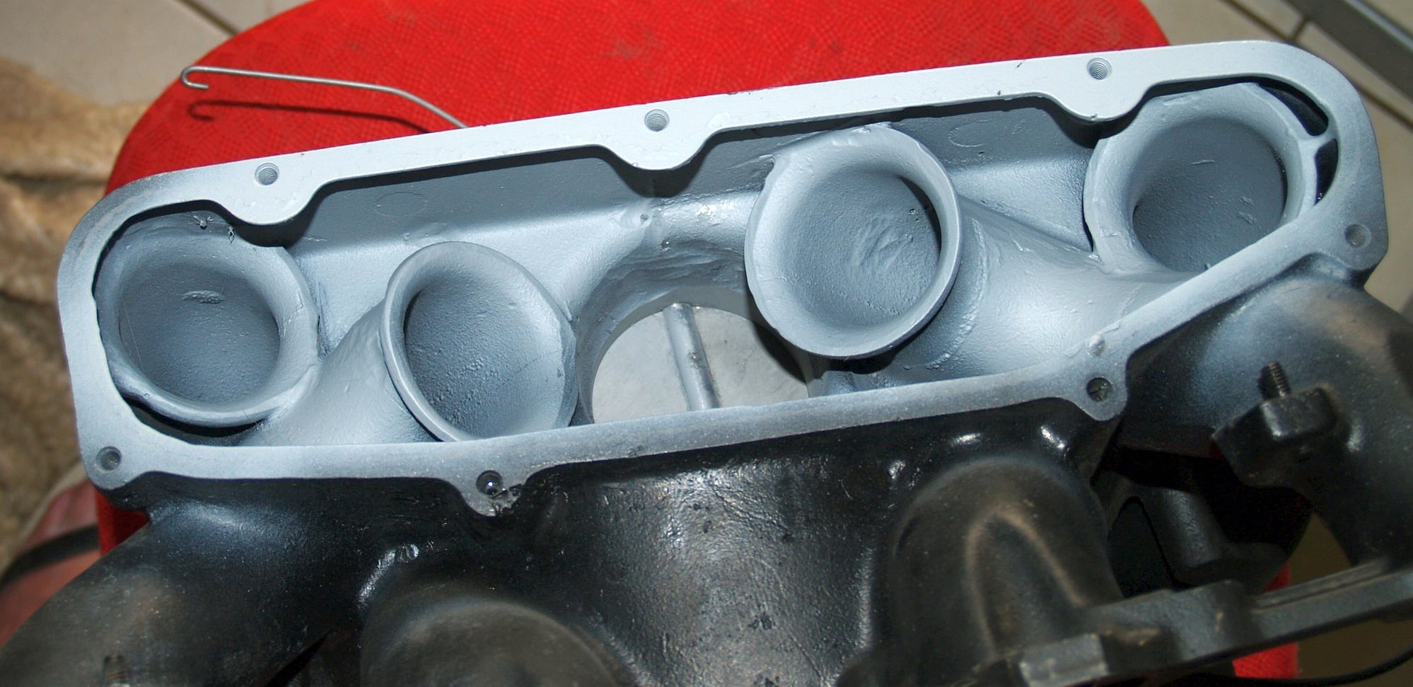
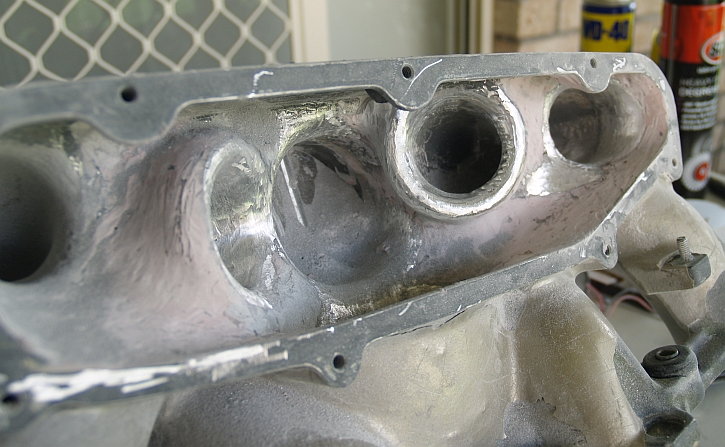
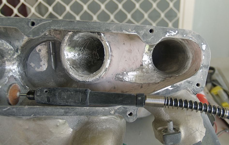
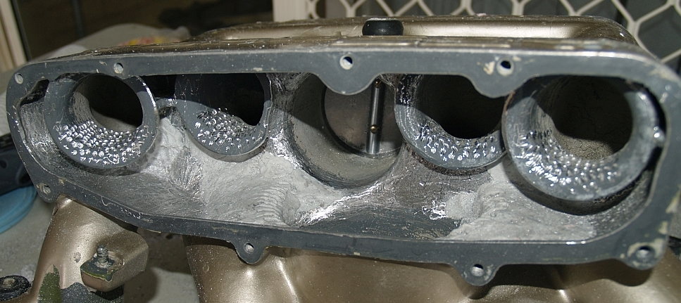
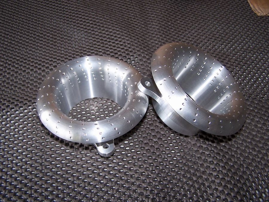
It centered on airflows at the pre-TB elbow (fitting a splitter), TB plenum (another splitter), and upper plenum intake bellmouths and runners (tapering of intakes and forming mathematically optimum bellmouth lips).
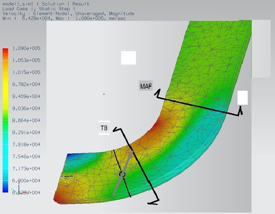
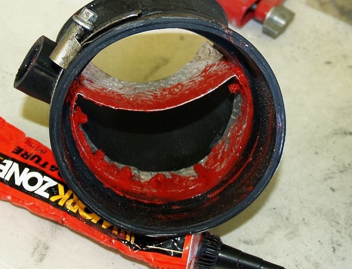
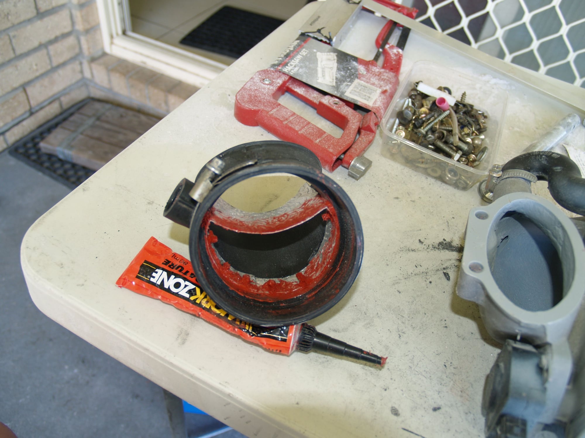
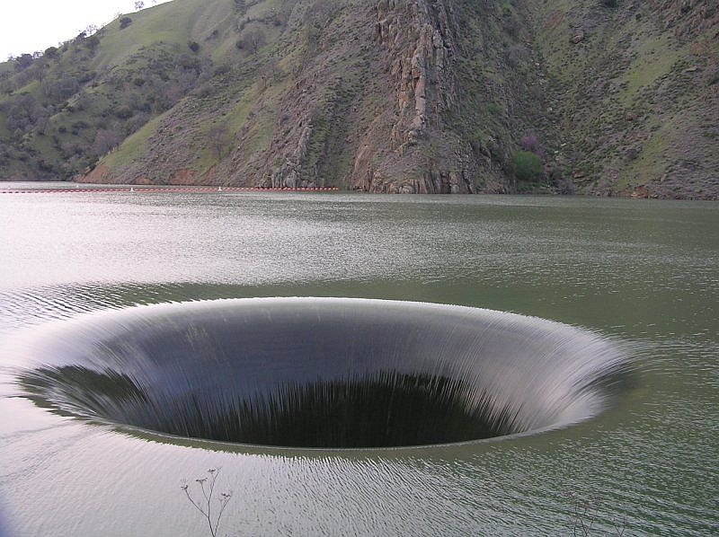
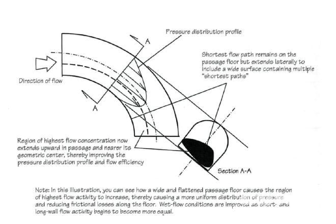
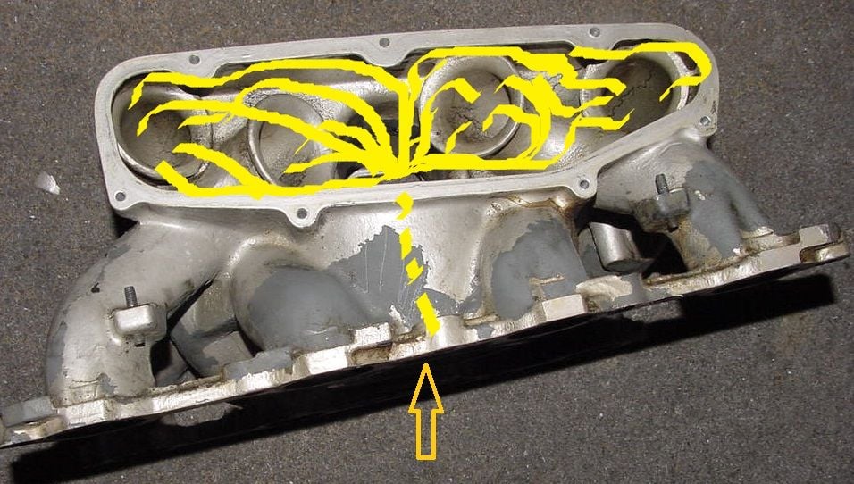
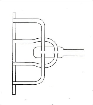
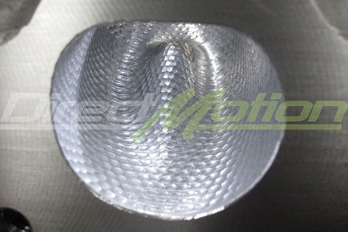
Air flowing through dog-legs etc wants to take the shortest path, shown by the red area on the inside of the turn.
This brings it across the face of the partly opened butterfly plate, resulting in a turbulence shadow, or wake.
The best flow occurs when the plate is at about 45 deg, ie parallel to the airflow.
Beyond that, it goes back to the air flowing obliquely across the plate, again leaving a turbulence shadow.
To alleviate this, many manifolds incorporate turning vanes, or splitters, to separate flow cleanly to each side on the butterfly throttle plate.
LOVE IT! inlet guide vanes!! anywhere there is a curve, you need these. reduces flow distubances and pressure drops across a turn in the air flow.
I haven't seen any issues and have been in 100s of races now, most all with a caution mid race with no issues at all.
if the lines are at 50psi or 75psi as they were on the Holbert S4, do you know what the boiling point is for gasoline? I have a hard time believing that there is that much heating going , having played with a hot engine and have drained fuel from the tank and it wasn't even warm after practice as I wanted to take some fuel out before qualifying from quarter tank to 1/8 tank.
LOVE IT! inlet guide vanes!! anywhere there is a curve, you need these. reduces flow distubances and pressure drops across a turn in the air flow.
Good to hear.
I think that vane guiding air on to the butterfly may be responsible for a reasonable percentage of my gains.
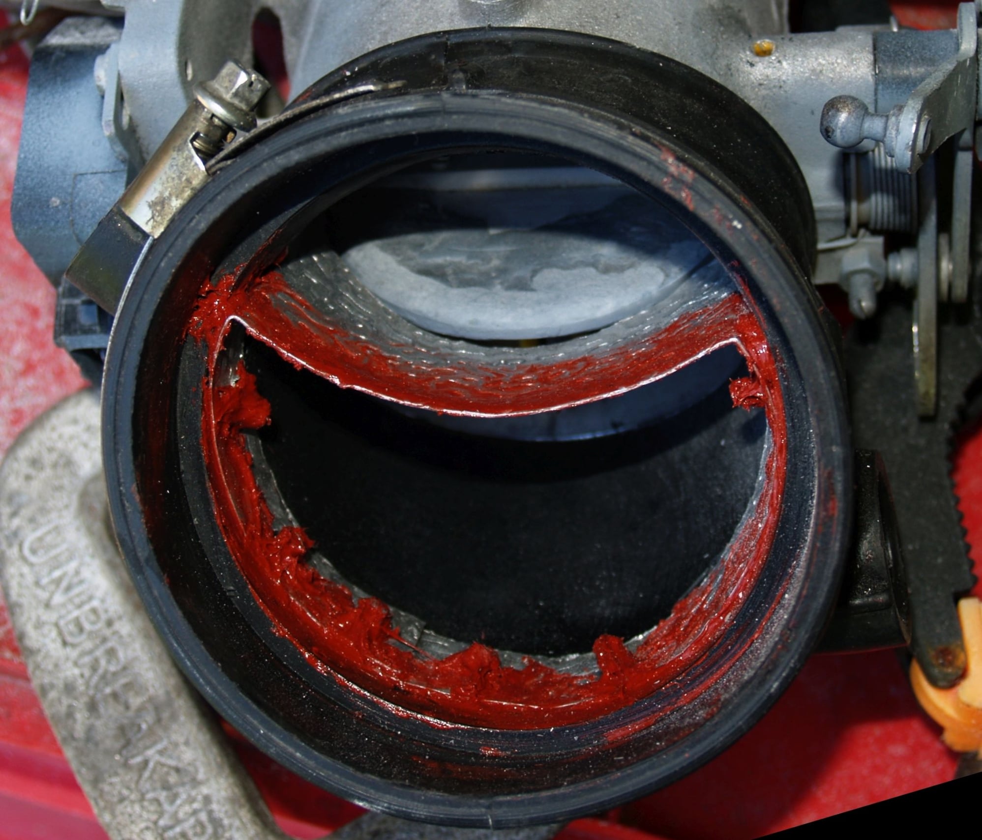
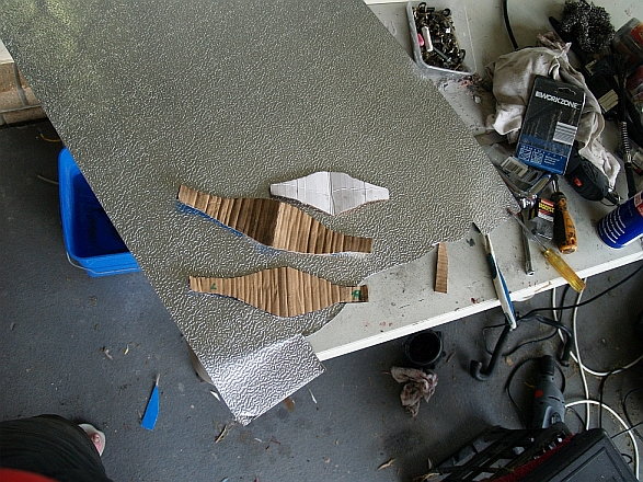
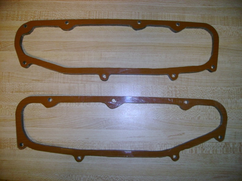
As you can see, dead simple to fabricate. You can copy it for free. :-) LOL
If you are speaking of the peak torque, this manifold will in my opinion and prediction produce a ton of it compared to the stock S4 intake. At low rpms, however, the stock S4 intake manifold is hard to beat for torque production, making it in my opinion a very good manifold for automatic cars. But for manual transmission (normally aspirated) cars, the stock S4 intake is in my opinion an unnecessary compromise and a single plenum manifold with straight and long runners will be better. These are all my personal opinions.
For a turbo street car, you kind of want to go into either corner solution. Either a big turbine and manifold with most torque at low rpms before the turbine spools or a smaller turbine and a short-runner stub intake that will help at the very top end. In either case, the turbo can fill in any torque curve hole in the mid range rpms. I understand that this is turbo case is a total niche case with about 10 turbo 928s out there, so it of course should have approximately zero influence on any commercial 928 intake manifold production effort. Just bringing this up here to explain why my interests on these manifold topics are somewhat orthogonal to almost everyone else's interests.
Perhaps worth noting is that I'm not trying to make a manifold to replace the stock manifold on a stock engine in a stock car equiped with a stock automatic transmission.
I never set out to build an "Edelbrock Torker".
I have, however, installed as many stroker engines in front of automatics as I've installed in manual transmission cars.....so I've got a really good idea of what is needed and what I'm trying to accomplish.
I'm the "poster child" for not trading torque for horsepower....anyone that has followed any of my thoughts and ramblings on this Forum is aware of that.
However, as my engine development has progressed, it became pretty obvious that the 6.5 liter version of my engines made a "surplus" of low rpm torque and that moving some of that "grunt" higher up in the rpm range was actually desirable.
The development of the 5.9 liter engine was partially a result of that....and although many thought (including you) I was making a huge mistake by going down in displacement, the results of that engine were absolutely outstanding.....I lost virtually nothing and gained the ability to spin a large displacement 928 engine higher in the rpm range.
My 6.5 liter and the 5.9 liter engines are my target market. I also believe that people with modified 5.0 engines (cams, headers, exhaust) will also gain from my manifold.
Like anything I do, it will be thoughtly tested and developed.
Even as much as I dislike automatic transmissions....I think many overlook the fact that the torque convertor acts as a LOWER first gear....allowing the engine to "freewheel" up to a higher RPM where it does make more horsepower which is then converted to torque !! Many drag racers in fact prefer the automatic for a number of reasons but the massive launch capability is one of them. Consistency being another
I'll be back soon to complete explanations, but for the moment many image sets are reasonably self explanatory.
Cheers
Upfixen
You hit the nail on the head Strosec, , and, might I say, seem the only Rennlister who has shown this level of understanding of the airflow problems.
Everyone else is capable of amazing machine work, but with airflow they're stabbing in the dark, and with moving air you just can't do that.
Below I've posted a spread of stuff out my "aero" library. It shows the why's and wherefore's behind my intake manifold performance gains, and the subtleties of airflow behaviour.
Intake air pathway on 928 S4:
An understanding (and application) of this was at the core of my S4 intake manifold modifications.
It centered on airflows at the pre-TB elbow (fitting a splitter), TB plenum (another splitter), and upper plenum intake bellmouths and runners (tapering of intakes and forming mathematically optimum bellmouth lips).
Air flowing through dog-legs etc wants to take the shortest path, shown by the red area on the inside of the turn.
This brings it across the face of the partly opened butterfly plate, resulting in a turbulence shadow, or wake.
The best flow occurs when the plate is at about 45 deg, ie parallel to the airflow.
Beyond that, it goes back to the air flowing obliquely across the plate, again leaving a turbulence shadow.
To alleviate this, many manifolds incorporate turning vanes, or splitters, to separate flow cleanly to each side on the butterfly throttle plate.
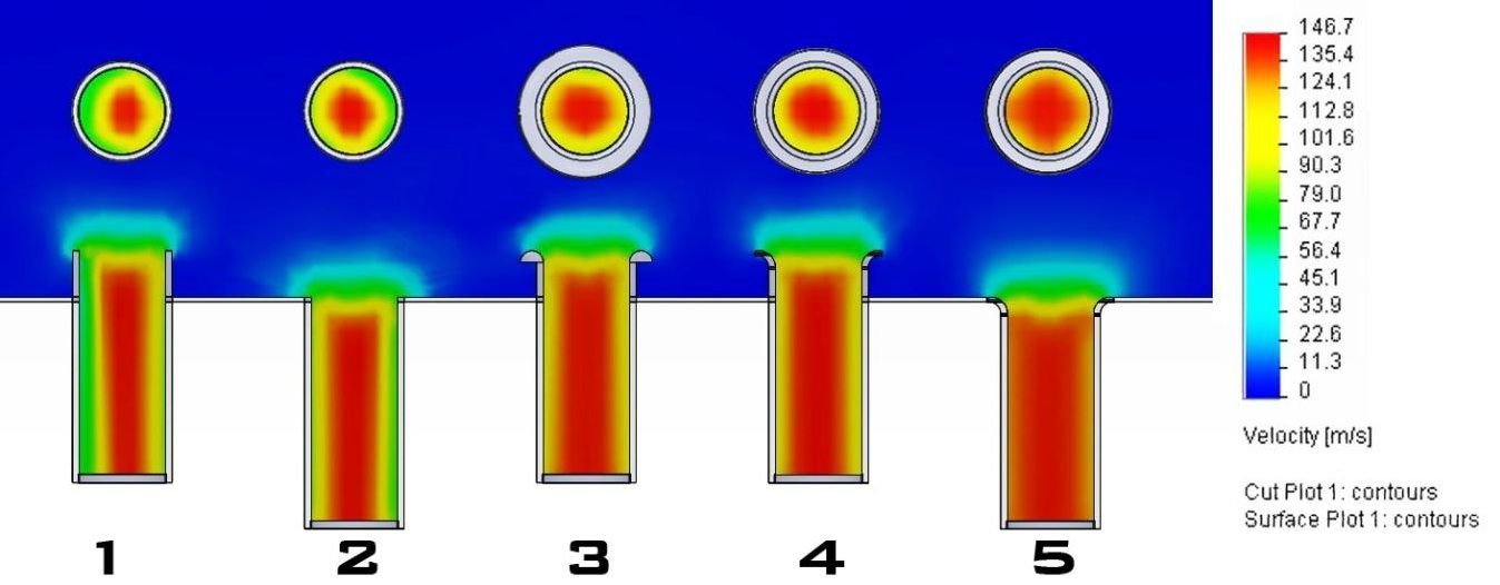
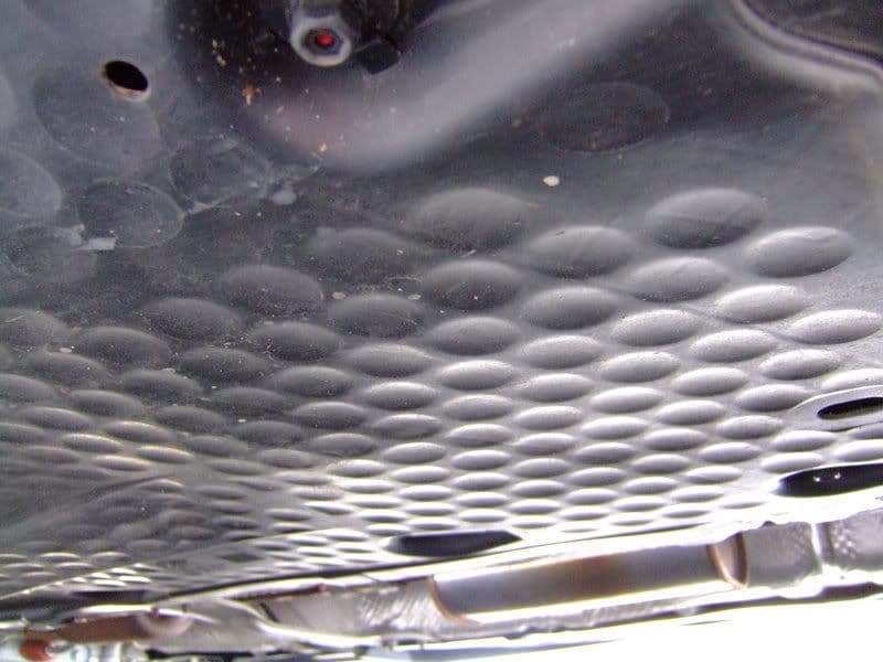
Good to see someone else do some cfd and incorporate divots as well. I remember discussing this and incorporating it into my SC intake and manifold design back in 2003...
The divots work miracles for laminar flow and a smooth boundary layer!!
The entire plenum roof of my sc is divoted for this reason.
Anyway, didn't mean to hijack, just pleased that others are becoming aware of aero as well.
I may have forgotten, but I run the stock S4 pump which I thought is the 044 version, correct?
AFR never goes lean, I moniter it all ways and have calibrated the AFR sytem with the wide band at the dyno. it never varies at the track, and I always (90%) run the car to the reserve light every qual or race session.
if it was to run near 13:1, It would show up on the AFR lights.
Mark,
The stock S4 fuel pump flows about 39 gallons/hr at 60 psi, the 044 flows about 70 gallons/hr at 60 psi. Pretty big difference.
I run the Bosch 040 in-tank pump until I hit 6 psi boost, then the 044 is suppose to kicks in. The Bosch 040 flows about 50 gal/hr.
I'm running the stock fuel regulator and fuel rails, with 52 lb-hr injectors and larger fuel lines.
Bill and I went to the dyno last week. We were have a few issues trying to get the car tuned (over heating because the fans
weren't working, low boost because the new belt was slipping, and the boost switch on the second fuel pump was disconnected...)
These things don't always work out as planned.
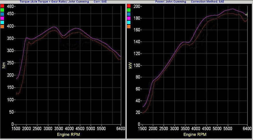
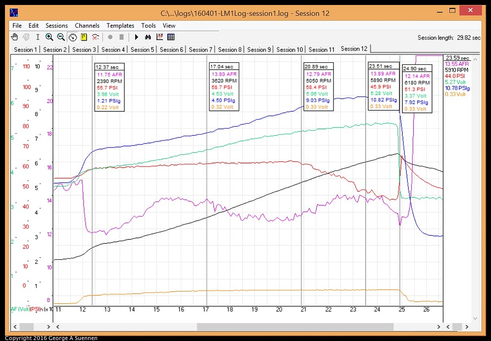
Here is a LM-1 log of the last dyno run with only the 040:
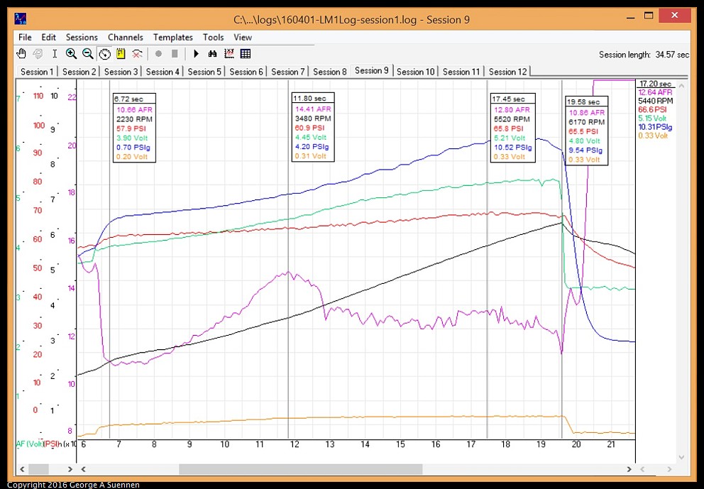
and one with both pumps:
Blue line is Boost, Green is MAF voltage, Red is Fuel Pressure, Purple is AFR, Black is RPM, and Yellow is Water Injection .
Notice the AFR was almost 14 on the first image and about 12.8 on the second, with the fuel pressure dropping below 45 psi
instead of being around 65 psi.This was with about 10.5 psi boost and a little over 410 rwph.
This could cause some serious issues if were we at a race.
__________________
George
90 S4 Grand Prix White (Murf #5)
94 GTS 5-Speed Midnight Blue
06 Cayenne S Havanna/Sand Beige (PASM) http://928.jorj7.com
I've got a couple of questions about your modifications.
First, did you by any chance fix anything, like a knock sensor or Hall sensor, between the before and after dyno runs?
The reason why I am asking is that I don't understand how simply improvements in manifold flow coefficients could give you the same percentage increase in torque at low and high rpms. The flow losses due to bad bellmouths etc. are proportional to the air velocity squared. At low rpms of an engine sized for high rpms, the air velocity is low and the bad vs. good bellmouths etc. don't matter and there's no torque increase that one can detect from improving runner flow coefficients. For example, the curvy runner #5 is filling about as well at low rpms as all the other short runners (based on some fuel trim data).
There are a couple of methods that would boost torque proportionally across the rev range. The first is increasing compression. The thermal efficiency gain is similar at low and high rpms. The second is increasing ignition advance from the base table. That's why I think that your gains could be consistent with fixing a sensor and taking out the error mode retard from the ECUs.
Resonance effects could boost the low-rpm torque. So one thing that could theoretically be happening in your manifold is that the resonance effect improvements improved the low rpm performance and better flow coefficients improved the high rpm performance.
I am having a hard time understanding how your modifications would increase the low rpm torque due to resonance effects, however. Reducing the plenum volume by filling the wall cavities will move the Helmholtz resonator torque peak to higher rpm, lowering the low rpm torque. Inserting the flow divider in the throttle body casting (which may help high rpm flow) will make the ram tube look more like two, independent short tubes to pulses, instead of like a single long u-shaped tube. This effective shortening of the ram tubes will also increase the torque peak rpm of the flappy closed mode (possibly insigificantly since you're not literally sealing off the two tube ends).
All the effects that I see in your manifold make me think that low rpm torque should be reduced and the first torque peak move to the right, if there's any significant effect on resonance tuning. My understanding is inconsistent with your results, so one of those has to be wrong (my understanding or your results).
So my question to you is _why_ do you think your modifications resulted in a torque increase that is proportional across the rpm range? Clearly, you're going by a theory here, but does that theory line up with the results?
The stock S4 fuel pump flows about 39 gallons/hr at 60 psi, the 044 flows about 70 gallons/hr at 60 psi. Pretty big difference.
I run the Bosch 040 in-tank pump until I hit 6 psi boost, then the 044 is suppose to kicks in. The Bosch 040 flows about 50 gal/hr.
I'm running the stock fuel regulator and fuel rails, with 52 lb-hr injectors and larger fuel lines.
Bill and I went to the dyno last week. We were have a few issues trying to get the car tuned (over heating because the fans
weren't working, low boost because the new belt was slipping, and the boost switch on the second fuel pump was disconnected...)
These things don't always work out as planned.
Here is a LM-1 log of the last dyno run with only the 040:
and one with both pumps:
Blue line is Boost, Green is MAF voltage, Red is Fuel Pressure, Purple is AFR, Black is RPM, and Yellow is Water Injection .
Notice the AFR was almost 14 on the first image and about 12.8 on the second, with the fuel pressure dropping below 45 psi
instead of being around 65 psi.This was with about 10.5 psi boost and a little over 410 rwph.
This could cause some serious issues if were we at a race.
__________________
George
90 S4 Grand Prix White (Murf #5)
94 GTS 5-Speed Midnight Blue
06 Cayenne S Havanna/Sand Beige (PASM) http://928.jorj7.com
bill has had the wide band in my car. I run the 044 pump without the stock fuel regulator. a very nice RRFR that seems to handle fuel flows very well.
I have no issues with lean. if i did, would see it on the wide band and with my 100% on , AFR i the car.... if i ever got to 13:1, it would show. i did a test to verify that.. with a manual switch on the fuel enrichment circuit on the AFM cars, i was able to click on and off that circuit and see the AFR go lean to 13:1. at that same RPM, i did the test at the dyno to see what it was measuring, and it showed the same value. its not super accurate, but if there was a change from 11:1 to 13:1, i would be able to detect it, and its never happened... no mater how long the race, or how long the caution or the outside temps. and this is generally with very little fuel in the tank too.


 04-17-2016, 03:01 PM