

Gain 100HP with an intake manifold change?? - Cross post from Ferrari Chat
 03-28-2016, 03:20 PM
#421
Rennlist Member
maybe this still counts as a patch to you, but...
some Japanese cars (RX7 turbo, MR2, etc) have a "fuel pump resistor pack"...runs the pump at 9v or so for most driving and then goes full 12-14V at a certain TPS/MAP point.
their way of getting long life and better economy from a high-flow pump,. at low load.
and, they're pretty small (grey thing) so they could fit anywhere, even in a 928 engine bay
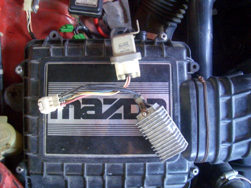
and here's a wiring diagram...looks like a relay+resistor combo...pump normally gets powered through resistor, until the relay coil trips and closes the 'direct' current path.
http://www.rx7club.com/attachments/g...p_resistor.jpg
some Japanese cars (RX7 turbo, MR2, etc) have a "fuel pump resistor pack"...runs the pump at 9v or so for most driving and then goes full 12-14V at a certain TPS/MAP point.
their way of getting long life and better economy from a high-flow pump,. at low load.
and, they're pretty small (grey thing) so they could fit anywhere, even in a 928 engine bay
and here's a wiring diagram...looks like a relay+resistor combo...pump normally gets powered through resistor, until the relay coil trips and closes the 'direct' current path.
http://www.rx7club.com/attachments/g...p_resistor.jpg
) of 8 ITBs, but really tiny, attached at the intake ports of each cylinder port of the stock intake. at WOT, they would open and provide additional air and fuel beyond what the stock intake would provide. only a WOT event, kind of like NOS, but without the bottle.
 03-28-2016, 03:31 PM
#422
Rennlist Member
Join Date: Feb 2011
Location: Mostly in my workshop located in Sweden.
Posts: 2,235
Received 467 Likes
on
250 Posts
I always had a vision (maybe a little blurred ill admit ) of 8 ITBs, but really tiny, attached at the intake ports of each cylinder port of the stock intake. at WOT, they would open and provide additional air and fuel beyond what the stock intake would provide. only a WOT event, kind of like NOS, but without the bottle.
) of 8 ITBs, but really tiny, attached at the intake ports of each cylinder port of the stock intake. at WOT, they would open and provide additional air and fuel beyond what the stock intake would provide. only a WOT event, kind of like NOS, but without the bottle.�ke
03-28-2016, 03:33 PM
#423
Rennlist Member
maybe the easy solution is to just bolt on the NOS system again. there is 50-100hp and the only inconvenience is filling the bottle before each race.
Now, if I could just get it legalized in SCCA/NASA/ PCA competition.
Now, if I could just get it legalized in SCCA/NASA/ PCA competition.
03-28-2016, 05:03 PM
#424
Chronic Tool Dropper
Lifetime Rennlist
Member
Lifetime Rennlist
Member

And definitely you don't want a rising-rate regulator. Sharktuning takes that out of the picture, such that "field adjustments" of any pressure regulator would be , um, counterproductive.
Start shopping now for the pieces of wiring harness you'll need for Sharktuning. Mark A is currently or has recently parted a 1989 car so the later bits might be available for that upgrade. I had my "spare" LH controller upgraded to 1989 diagnostic smarts so it could be a drop-in for my car. You'll likely need to have your early controllers similarly upgraded for full functionality. Jim C can tell you what will be needed. You'll also be upgrading to Alpha N so your MAF will be removed. There are some sensors needed for that upgrade too. MAP and inlet air temp would be my guess, but Jim will tell you. They will also tell you what injectors to buy. You'll probably want an air cleaner too. The list goes on!
03-28-2016, 05:12 PM
#425
Rainman
Rennlist Member
Rennlist Member
I always had a vision (maybe a little blurred ill admit ) of 8 ITBs, but really tiny, attached at the intake ports of each cylinder port of the stock intake. at WOT, they would open and provide additional air and fuel beyond what the stock intake would provide. only a WOT event, kind of like NOS, but without the bottle.
) of 8 ITBs, but really tiny, attached at the intake ports of each cylinder port of the stock intake. at WOT, they would open and provide additional air and fuel beyond what the stock intake would provide. only a WOT event, kind of like NOS, but without the bottle. 03-28-2016, 05:29 PM
#426
Chronic Tool Dropper
Lifetime Rennlist
Member
Lifetime Rennlist
Member
You mean like a separate Y-shape pipe over each port, one side of the Y with a separate throttle and injector and an air cleaner on it, the other from the more conventional longer-runner intake and its own throttle and injectors? Maybe a different-length stack over the "full-throttle" throttles.
Yep, that would simplify things a lot! Maybe the logical extension of that would be a version of Daniel's multi-section mailbox manifold illustrated in post 408 above, each with its own throttle plate and injector. Just pick the calliope pipe that sounds the best.
Yep, that would simplify things a lot! Maybe the logical extension of that would be a version of Daniel's multi-section mailbox manifold illustrated in post 408 above, each with its own throttle plate and injector. Just pick the calliope pipe that sounds the best.
03-28-2016, 05:59 PM
#428
Drifting
maybe this still counts as a patch to you, but...
some Japanese cars (RX7 turbo, MR2, etc) have a "fuel pump resistor pack"...runs the pump at 9v or so for most driving and then goes full 12-14V at a certain TPS/MAP point.
their way of getting long life and better economy from a high-flow pump,. at low load.
and, they're pretty small (grey thing) so they could fit anywhere, even in a 928 engine bay
and here's a wiring diagram...looks like a relay+resistor combo...pump normally gets powered through resistor, until the relay coil trips and closes the 'direct' current path.
http://www.rx7club.com/attachments/g...p_resistor.jpg
03-28-2016, 06:27 PM
#429
Rainman
Rennlist Member
Rennlist Member
Boost-a-pump makes the voltage to pump higher than stock, looks like from 14v to 17-18V to "overdrive" it, rather than cutting voltage until full power needed like the Japanese.
I was wondering about something like that to drive an electric radiator fan...
03-28-2016, 07:18 PM
#431
Rainman
Rennlist Member
Rennlist Member
V = I/R...but if powered/grounded by the battery it's 12-14V no matter what...say at 10 amps to run the pump.
V = I/R
VR = I
R = I/V
add a 1.5 ohm (high watt) resistor, would make it 6 amps @ 12V?
03-28-2016, 08:08 PM
#432
Former Sponsor

Lots of different ways to solve this problem.
The simple way, for me, is to match the return capacity of the FPR (or two FPRs) to the fuel pump.
Keeps the pump from struggling and keeps the fuel cooler without changing somethng else.
The simple way, for me, is to match the return capacity of the FPR (or two FPRs) to the fuel pump.
Keeps the pump from struggling and keeps the fuel cooler without changing somethng else.
03-28-2016, 08:38 PM
#433
Rennlist Member
thinking about it some more, wouldn't a resistor/relay setup leave voltage constant but only knock down current?
V = I/R...but if powered/grounded by the battery it's 12-14V no matter what...say at 10 amps to run the pump.
V = I/R
VR = I
R = I/V
add a 1.5 ohm (high watt) resistor, would make it 6 amps @ 12V?
V = I/R...but if powered/grounded by the battery it's 12-14V no matter what...say at 10 amps to run the pump.
V = I/R
VR = I
R = I/V
add a 1.5 ohm (high watt) resistor, would make it 6 amps @ 12V?
if you were running 10amps to start at full voltage, that means the effective resistance of the motor is 1.2ohms and 10amps flow. (120watts) add the 1.5ohm resistance, and suddenly the motor is only seeing 4.4 amps
both the motor and the resistor are producing I^2R or 29 or 23 watts.
you have just quartered the power of the pump with the 1.5ohm resistor.
03-28-2016, 08:42 PM
#434
Rennlist Member
03-28-2016, 08:44 PM
#435
Rennlist Member
You mean like a separate Y-shape pipe over each port, one side of the Y with a separate throttle and injector and an air cleaner on it, the other from the more conventional longer-runner intake and its own throttle and injectors? Maybe a different-length stack over the "full-throttle" throttles.
Yep, that would simplify things a lot! Maybe the logical extension of that would be a version of Daniel's multi-section mailbox manifold illustrated in post 408 above, each with its own throttle plate and injector. Just pick the calliope pipe that sounds the best.
Yep, that would simplify things a lot! Maybe the logical extension of that would be a version of Daniel's multi-section mailbox manifold illustrated in post 408 above, each with its own throttle plate and injector. Just pick the calliope pipe that sounds the best.
