
Changing Motor Mounts Tomorrow
 12-08-2007, 01:55 AM
#1
Three Wheelin'
Thread Starter
Join Date: Sep 2007
Location: Ridgecrest, California
Posts: 1,363
Likes: 0
Received 146 Likes
on
30 Posts
I"ve been getting vibrations around 1200 RPM and the engine does not rock when starting (nor does it rock when reved). There was also about 1.5 finger widths gap between the "hooks" in the motor mount housings (top and bottom). So I ordered Motor Mounts and they came earlier this week. So now I'm going to attempt to change them out this weekend (starting early tomorrow morning).
I'm using solid MMs I ordered from 928Motorsports and I'm using the procedure outlined by Pirtle. In addition, I'm using Andrew Olson's design/method of supporting the engine (using 4X4s). Thanks for the idea Andrew!
I'll probably be taking some pics and can post if anyone's interested...will check in later.....
 12-08-2007, 12:57 PM
#5
Addict
Rennlist Member
Rennlist Member
12-08-2007, 04:05 PM
#7
Three Wheelin'
Thread Starter
Join Date: Sep 2007
Location: Ridgecrest, California
Posts: 1,363
Likes: 0
Received 146 Likes
on
30 Posts
OK....Checking in....
THANKS for the vote of confidence, guys!
Started this morning at 0745 and completed the removal of the old mounts at exactly 1145 (4 hours).
I'm taking my time and taking pics at every step. I decided to stop now and download pics and eat lunch. I'll also upload some of the pics before I get back out there.
Working on a clean compartment and engine is SSSOOOOOOO nice!! I didn't even have to wash my hands when I was done!
Trending Topics
12-08-2007, 05:07 PM
#8
Shameful Thread Killer
Rennlist Member
Rennlist Member


 12-08-2007, 06:43 PM
#10
Three Wheelin'
Thread Starter
Join Date: Sep 2007
Location: Ridgecrest, California
Posts: 1,363
Likes: 0
Received 146 Likes
on
30 Posts
I'm feelin' the love
OK...here's the pics from this mornings work...
First of all, I followed Pirtle's writeup step by step - So he gets the credit for putting all this down in the first place. Made things go smooth.
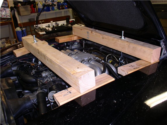
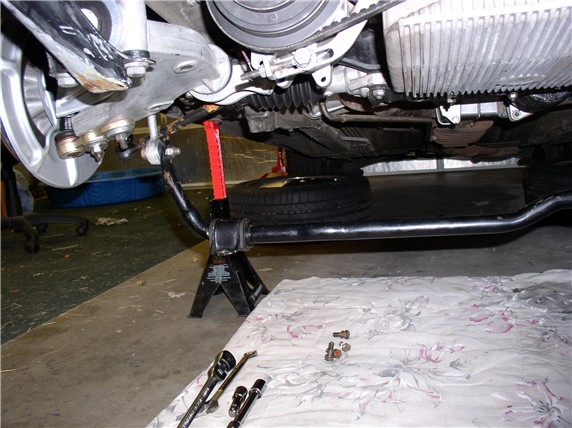
Last Weekend, I prefabricated the engine support using Andrew Olson's design. Went to Home Depot and got a 4X4 and had them cut it to 35.25" and a 37.25" lengths. The 35.25" piece goes up front and the 37.25" at the back of the engine. Also bought 1/2" X 10" eye bolts (w/nuts) and large washers. All the parts were about $22. I cut some scrap 2X4 into about 12" lenghts (4 of 'em) and counter sunk holes to fit over the fender bolt heads/washers so the 2X4s would lay flush. I removed the hood shocks to make room for the 4X4. Here's what they look like on the car with the hardware attached. THANKS again, Andew!
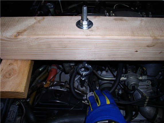
and here's where I connected the link's to the lift point (front)
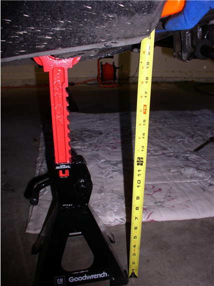
I disconnected the battery and raised the vehicle as high as possible. About 20" from floor to lift point.
I removed the front wheels next although it would have been easier to loosen the lugs while weight was on wheels - so I had to use an impact wrench to get the wheels off once off the ground. Then I took off the oil filter and removed the 10mm bolt from the wiring harness.
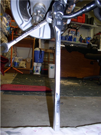
Next, I loosend the 19mm bolts connecting the sway bar to the drop links. I used a socket wrench with a very long hanele and made loosening bolts a lot easier.
I took off the sway bar to body bolts and swung the sway bar down.
Next, I loosened the four 13mm nuts holding the steering rack plate to the cross member
Then removed the 17mm bolt on the plate to the left of the steering rack (driver's side)
Next post....
OK...here's the pics from this mornings work...
First of all, I followed Pirtle's writeup step by step - So he gets the credit for putting all this down in the first place. Made things go smooth.
Last Weekend, I prefabricated the engine support using Andrew Olson's design. Went to Home Depot and got a 4X4 and had them cut it to 35.25" and a 37.25" lengths. The 35.25" piece goes up front and the 37.25" at the back of the engine. Also bought 1/2" X 10" eye bolts (w/nuts) and large washers. All the parts were about $22. I cut some scrap 2X4 into about 12" lenghts (4 of 'em) and counter sunk holes to fit over the fender bolt heads/washers so the 2X4s would lay flush. I removed the hood shocks to make room for the 4X4. Here's what they look like on the car with the hardware attached. THANKS again, Andew!
and here's where I connected the link's to the lift point (front)
I disconnected the battery and raised the vehicle as high as possible. About 20" from floor to lift point.
I removed the front wheels next although it would have been easier to loosen the lugs while weight was on wheels - so I had to use an impact wrench to get the wheels off once off the ground. Then I took off the oil filter and removed the 10mm bolt from the wiring harness.
Next, I loosend the 19mm bolts connecting the sway bar to the drop links. I used a socket wrench with a very long hanele and made loosening bolts a lot easier.
I took off the sway bar to body bolts and swung the sway bar down.
Next, I loosened the four 13mm nuts holding the steering rack plate to the cross member
Then removed the 17mm bolt on the plate to the left of the steering rack (driver's side)
Next post....
12-08-2007, 06:58 PM
#11
Three Wheelin'
Thread Starter
Join Date: Sep 2007
Location: Ridgecrest, California
Posts: 1,363
Likes: 0
Received 146 Likes
on
30 Posts
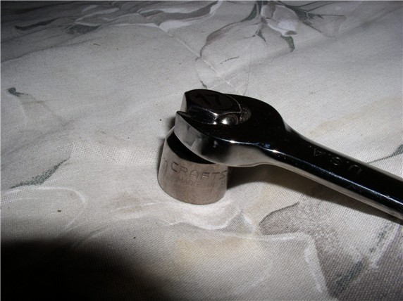
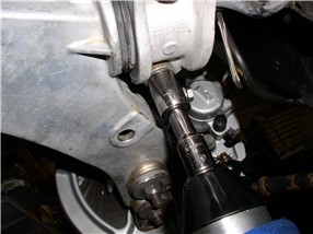
In order to get at the four 17mm bolts/nuts holding the steering rack, I used a short socket that came with the ratcheting wrenches. This worked great for getting into the tight places above the rack to counter hold the bolts
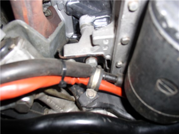
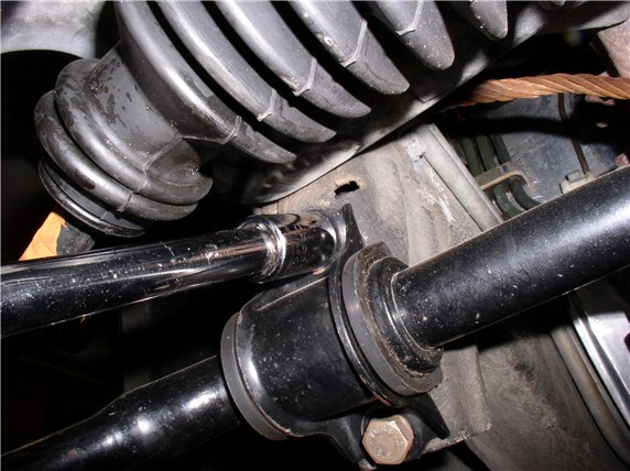
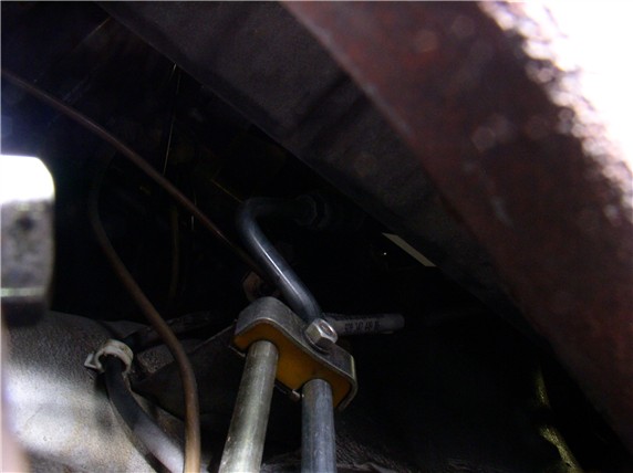
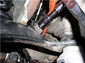
I added a step to Pirtle's process at this point. Before dropping the steering rack, I needed to take out the PS line clamp on the driver's side fender - here's a picture of it - can be accessed either from top or below. Just follow the PS steel lines from the rack up the side of the engine bay and you should see it. I got to it from the top and used a 10mm ratcheting wrench.
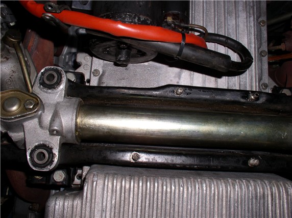
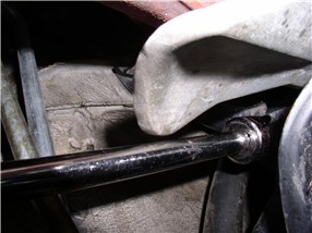
Next, I removed the four 13mm nuts holding the rack plate in place and removed the steering rack plate.
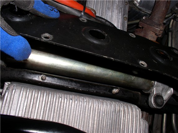
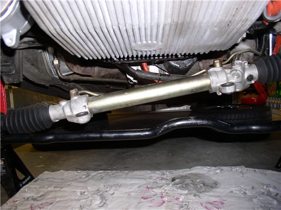
exposing the steering rack which can now be pulled down and maneuvered around.
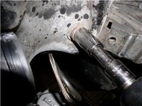
Then I loosened the 19mm nuts at the bottom of the motor mounts (under the cross member)
And removed the 13mm and 17mm bolts that hold the mount housing to the engine block
Next post....for some reason I can't upload all the pictures in a single post...sorry!
I added a step to Pirtle's process at this point. Before dropping the steering rack, I needed to take out the PS line clamp on the driver's side fender - here's a picture of it - can be accessed either from top or below. Just follow the PS steel lines from the rack up the side of the engine bay and you should see it. I got to it from the top and used a 10mm ratcheting wrench.
Next, I removed the four 13mm nuts holding the rack plate in place and removed the steering rack plate.
exposing the steering rack which can now be pulled down and maneuvered around.
Then I loosened the 19mm nuts at the bottom of the motor mounts (under the cross member)
And removed the 13mm and 17mm bolts that hold the mount housing to the engine block
Next post....for some reason I can't upload all the pictures in a single post...sorry!
12-08-2007, 07:40 PM
#12
Three Wheelin'
Thread Starter
Join Date: Sep 2007
Location: Ridgecrest, California
Posts: 1,363
Likes: 0
Received 146 Likes
on
30 Posts
Next, I needed to lift the engine - about an inch. I removed the air box (both upper and lower halves when I put the 4X4 engine support across the engine compartment). I put masking tape on the engine support bolt threads after snugging the nut down by hand.
Then tightened the nut until 1" of thread was exposed below the tape - make sure you check the clearance of the O2 sensor while lifting the engine. Mine was OK.
Next, I removed the lower motor mount nuts under the crossmember.
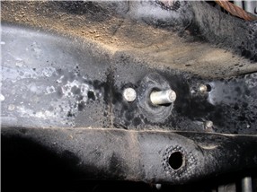
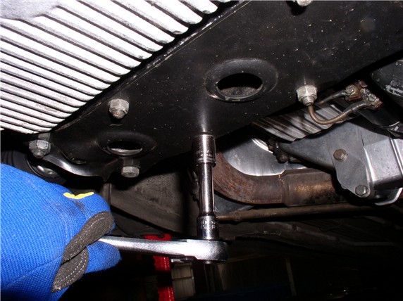
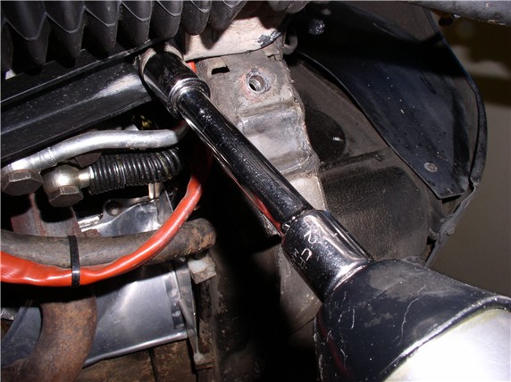
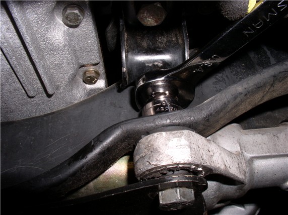
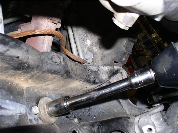
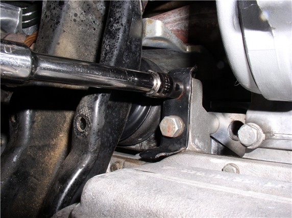
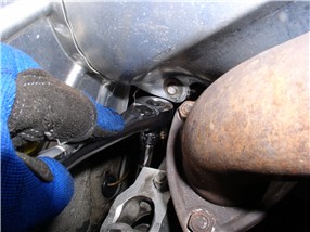
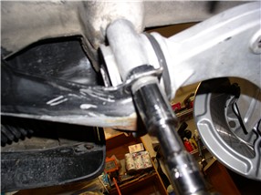
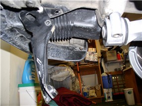
Then came the INFAMOUS crossmember upper support bracket bolts. I was warned about these. Rather than counter hold the nut from above in the engine compartment (as was suggested), I used a long socket extension on the rearward nut (driver's side) and a regular socket for the front. The passenger side did not seem to have space issues.
Here's the front bolt (driver's side):
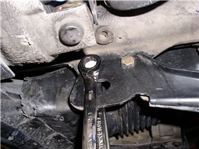
and the rear nut (driver's side) using a long extension
The driver's side come out easy by hand. But the Passenger side required tapping with a hammer and screwdriver. This one will be interesting to get back in.
Next, I loosened the front 17mm bolt on the tow hook at the front of the chassis and removed the 2nd (rear) bolt.
Then I removed the two 19mm bolts at the end of the tow hook - these are the two bolts used to mount the front of the Lower Control Arm as well.
The tow hook should then swing down freely.
Next, I removed the two 19mm bolts at the rear of the control arm mounts
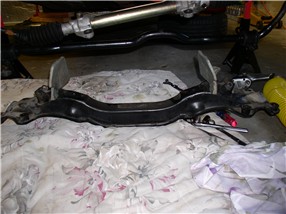
Finally, I removed the two 19mm bolts holding the cross member - one at each end.
Then I maneuvered the crossmember down enough to remove the motor mounts. Then some additional maneuving to get the crossmember out completely.
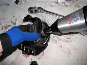
After the motor mounts were out, I used the air impact wrench to get the upper bolt off the mount.
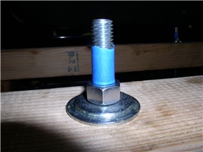
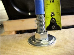
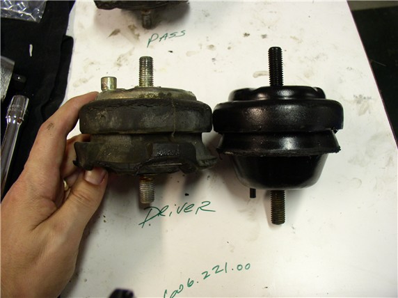
Then I compared the old and new mounts side by side and looked for differences. The first obvious difference is mine's flattened. Second, it looks like I'll have to grind off the little pin in the top of the mount. And it looks like no pin to hold the mount in place while tightening on the new mount.
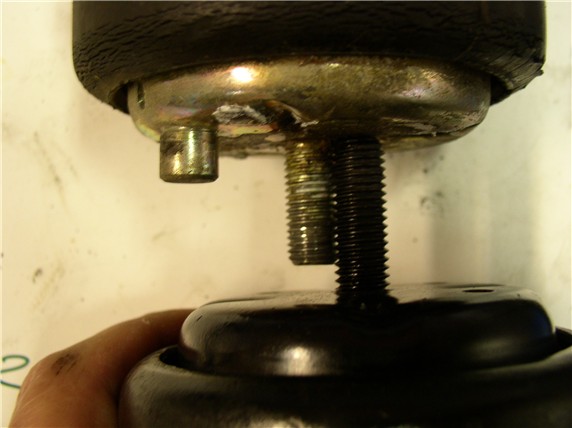
I also looked at the clearance I had between the lower motor mount stud and the steering rack banjo bolts while the rack was in the car and noticed I would have very little room left for a longer stud on the new mount. So I compared stud lengths on the mounts and the new one is about 1/4" longer (actually about 3/16"). So rather than take any chances, I'll remove about 3/16" of the threads on the lower motor mount stud.
Well, that's as far as I got this morning before I broke for lunch and posted these pics. Now it's back to work. I'll make the mods to the new mounts first. Then I'll do some cleaning - I actually missed a couple of bolts and there are areas on the crossmember I couldn't get to before so now's the perfect time to do some more cleaning before reassembly. It's 3:45 pm now - probably won't finish tonight but will check in before hittin' the sack....
Then tightened the nut until 1" of thread was exposed below the tape - make sure you check the clearance of the O2 sensor while lifting the engine. Mine was OK.
Next, I removed the lower motor mount nuts under the crossmember.
Then came the INFAMOUS crossmember upper support bracket bolts. I was warned about these. Rather than counter hold the nut from above in the engine compartment (as was suggested), I used a long socket extension on the rearward nut (driver's side) and a regular socket for the front. The passenger side did not seem to have space issues.
Here's the front bolt (driver's side):
and the rear nut (driver's side) using a long extension
The driver's side come out easy by hand. But the Passenger side required tapping with a hammer and screwdriver. This one will be interesting to get back in.
Next, I loosened the front 17mm bolt on the tow hook at the front of the chassis and removed the 2nd (rear) bolt.
Then I removed the two 19mm bolts at the end of the tow hook - these are the two bolts used to mount the front of the Lower Control Arm as well.
The tow hook should then swing down freely.
Next, I removed the two 19mm bolts at the rear of the control arm mounts
Finally, I removed the two 19mm bolts holding the cross member - one at each end.
Then I maneuvered the crossmember down enough to remove the motor mounts. Then some additional maneuving to get the crossmember out completely.
After the motor mounts were out, I used the air impact wrench to get the upper bolt off the mount.
Then I compared the old and new mounts side by side and looked for differences. The first obvious difference is mine's flattened. Second, it looks like I'll have to grind off the little pin in the top of the mount. And it looks like no pin to hold the mount in place while tightening on the new mount.
I also looked at the clearance I had between the lower motor mount stud and the steering rack banjo bolts while the rack was in the car and noticed I would have very little room left for a longer stud on the new mount. So I compared stud lengths on the mounts and the new one is about 1/4" longer (actually about 3/16"). So rather than take any chances, I'll remove about 3/16" of the threads on the lower motor mount stud.
Well, that's as far as I got this morning before I broke for lunch and posted these pics. Now it's back to work. I'll make the mods to the new mounts first. Then I'll do some cleaning - I actually missed a couple of bolts and there are areas on the crossmember I couldn't get to before so now's the perfect time to do some more cleaning before reassembly. It's 3:45 pm now - probably won't finish tonight but will check in before hittin' the sack....
12-08-2007, 08:05 PM
#13
Definately worth the time to do. The first thing I noticed after I did mine was there was no vibration while at idle. My alignment was off a little after I finished mine. You will notice the difference as soon as you fire up the car.
12-08-2007, 08:09 PM
#14
Team Owner
Nice Job, keep em flying, you can trim the MM stud after you fit it to the crossmember if you have a hand held grinder