
Changing Motor Mounts Tomorrow
 12-09-2007, 11:26 PM
#46
Three Wheelin'
Thread Starter
Join Date: Sep 2007
Location: Ridgecrest, California
Posts: 1,363
Likes: 0
Received 146 Likes
on
30 Posts
OK....I'M DONE!! 
I drove it this afternoon after checking a couple other things while the car was still up on stands (flex plate tension and crank endplay).
The drive was amazing! Wow! I mean WOW!! The engine rocks now on start and revs - never saw it do that before. And the ride - much smoother. I don't get that vibration at 1200 rpms anymore. I couldn't be happier with the results!! Really NICE!!
Started at 10:30 this morning and finished at 1:30 this afternoon (3 more hours) bringing the total time on task to 9.5 hours - plus I took a lot of pics. I figure without the pic taking maybe 8.5 or 9 hours total - definitely doable in a day.
So here's the rest of the pics for the remaining install I did today...
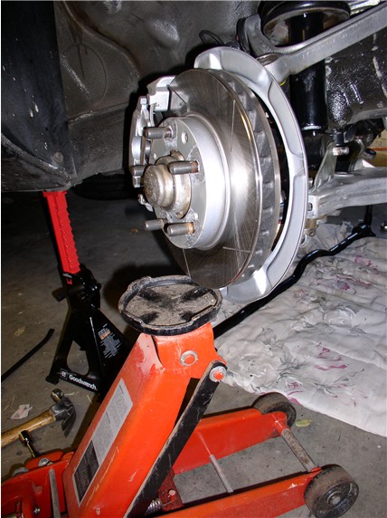
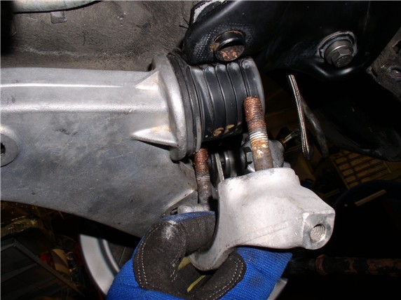
Since I removed the LCA to get the crossmember back in, I had struggled with getting the lower shock mount to line up with the LCA bracket - too many things under tension. So this morning I tried a different approach and used the floor jack to hold up the hub/upper ctl arm while I maneuvered the LCA into place. Took about 10 min.
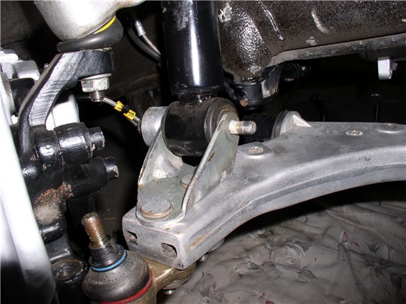
All I did at this point was insert the bolt with the stabilizer link on the back side to hold things in place while I re-inserted the lower ball joint stud in the steering knuckle.
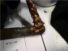
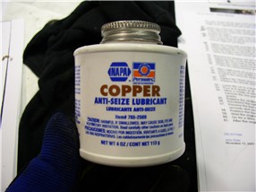
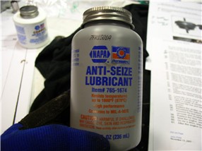
The WSM recommends applying Optimoly HT (Copper Anti-Freeze, er Anti-SEIZE) to the Lower control arm bolts before putting them back in (both forward and rear LCA bolts)
This is what I'm using for Optimoly HT:
And this is what I use for Optimoly TA (Aluminum colored anti-seize):
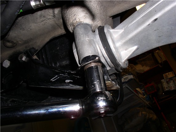
I installed the rear LCA bracket first:
I only tighten the 19MM bolts 'til there's about 1/8" gap between the bracket and the crossmember. I read that this will allow the car to settle easier after weight on wheels and a short drive. Then I torque it down after the car settles:
Then I installed the front 19MM LCA bolts along with the tow eye/guard bracket. These are torqued at this time 62ftlb.
Next, I re-installed the 17MM tow eye/guard bolt up front and torqued it down along with the front bolt - 33ftlb.
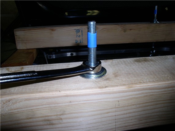
At this point, I lowered the engine. I had raised the engine 1 inch before the install (marked by the tape)
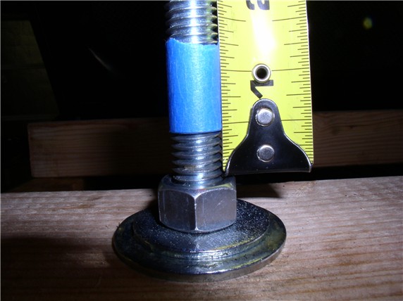
After I lowered the engine, I measured the new engine height resulting from the new mounts. Looks like it raised the engine about 1/2".
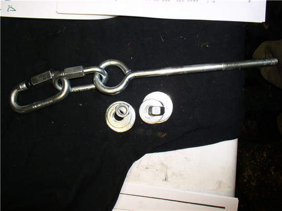
I removed the 4X4s and 2X4s. Someone asked what links I used for the engine support. The eye bolt is 10" long and 1/2" threads. These links are rated at over 2000lb for the small and over 3000lb for the large.
OK....next post...
I drove it this afternoon after checking a couple other things while the car was still up on stands (flex plate tension and crank endplay).
The drive was amazing! Wow! I mean WOW!! The engine rocks now on start and revs - never saw it do that before. And the ride - much smoother. I don't get that vibration at 1200 rpms anymore. I couldn't be happier with the results!! Really NICE!!
Started at 10:30 this morning and finished at 1:30 this afternoon (3 more hours) bringing the total time on task to 9.5 hours - plus I took a lot of pics. I figure without the pic taking maybe 8.5 or 9 hours total - definitely doable in a day.
So here's the rest of the pics for the remaining install I did today...
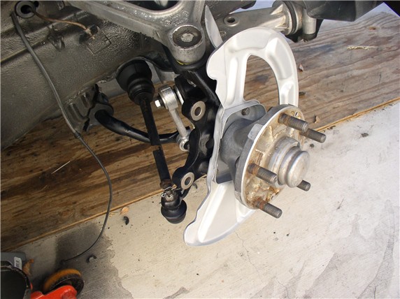
Since I removed the LCA to get the crossmember back in, I had struggled with getting the lower shock mount to line up with the LCA bracket - too many things under tension. So this morning I tried a different approach and used the floor jack to hold up the hub/upper ctl arm while I maneuvered the LCA into place. Took about 10 min.
All I did at this point was insert the bolt with the stabilizer link on the back side to hold things in place while I re-inserted the lower ball joint stud in the steering knuckle.
The WSM recommends applying Optimoly HT (Copper Anti-Freeze, er Anti-SEIZE) to the Lower control arm bolts before putting them back in (both forward and rear LCA bolts)
This is what I'm using for Optimoly HT:
And this is what I use for Optimoly TA (Aluminum colored anti-seize):
I installed the rear LCA bracket first:
I only tighten the 19MM bolts 'til there's about 1/8" gap between the bracket and the crossmember. I read that this will allow the car to settle easier after weight on wheels and a short drive. Then I torque it down after the car settles:
Then I installed the front 19MM LCA bolts along with the tow eye/guard bracket. These are torqued at this time 62ftlb.
Next, I re-installed the 17MM tow eye/guard bolt up front and torqued it down along with the front bolt - 33ftlb.
At this point, I lowered the engine. I had raised the engine 1 inch before the install (marked by the tape)
After I lowered the engine, I measured the new engine height resulting from the new mounts. Looks like it raised the engine about 1/2".
I removed the 4X4s and 2X4s. Someone asked what links I used for the engine support. The eye bolt is 10" long and 1/2" threads. These links are rated at over 2000lb for the small and over 3000lb for the large.
OK....next post...
 12-09-2007, 11:52 PM
#47
Three Wheelin'
Thread Starter
Join Date: Sep 2007
Location: Ridgecrest, California
Posts: 1,363
Likes: 0
Received 146 Likes
on
30 Posts
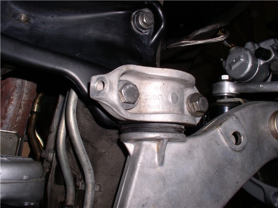
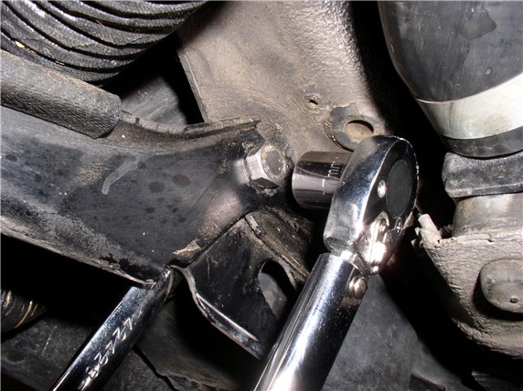
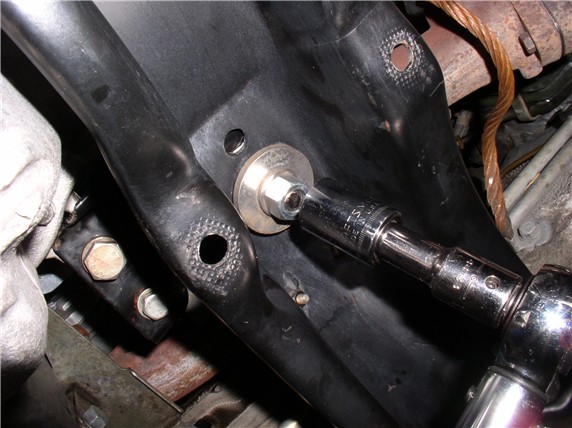
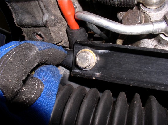
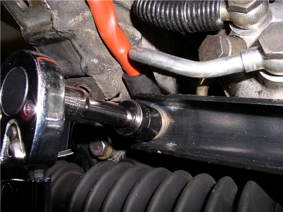
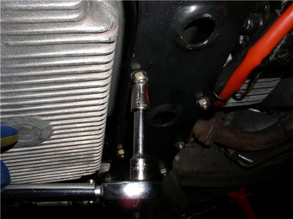
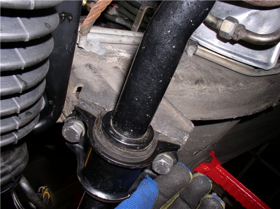
After lowering the engine, I torqued down the 19MM lower motor mount bolt - 62ftlb.
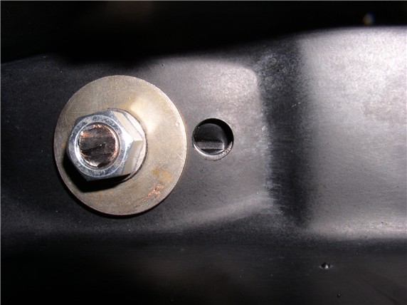
I also made sure the alignment holes were lined up. Normally there would be a pin here on the Porsche mounts to keep the upper and lower mount bracket fingers aligned.
Next came the steering rack. Put the four 13MM locking studs in the crossmember from the top.
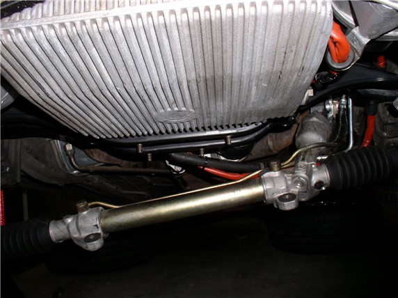
I maneuvered the rack back into the crossmember channel and held it with one had while getting the reiforcement plate lined up with the 13MM studs.

Then hand-tighten the four 13MM bolts to hold the plate in place
Next, I installed the single short 17MM bolt at the end of the reinforcement plate (hand tightened only so that the remaining four Steering rack 17MM bolts could be lined up and assembled).
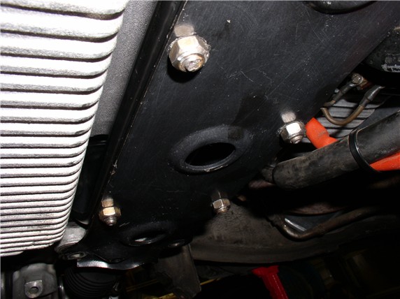
Then I installed the four 17MM steering rack bushing bolts and torqued them down - 33ftlb
Next, Torqued the single short 17MM bolt at the end of the plate - 33ftlb
And finally, torqued the four 13MM plate nuts - 17ftlb
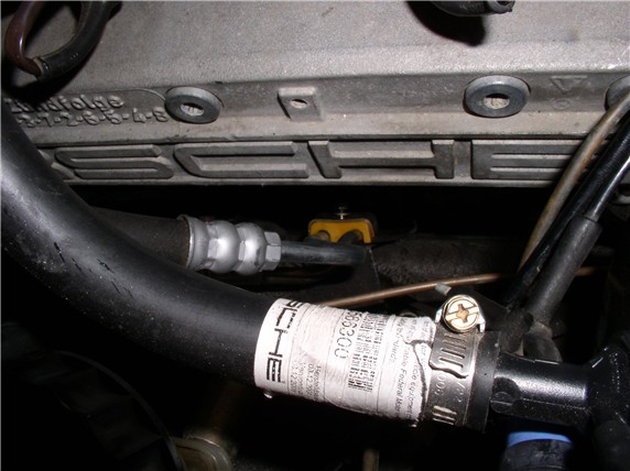
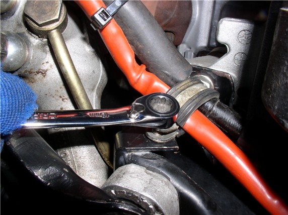
To finish off the steering, I then re-attached the PS line clamp to the side of the engine compartment. Best to reach this from the top using a 10mm ratchet wrench.
Next Post.....
I also made sure the alignment holes were lined up. Normally there would be a pin here on the Porsche mounts to keep the upper and lower mount bracket fingers aligned.
Next came the steering rack. Put the four 13MM locking studs in the crossmember from the top.
I maneuvered the rack back into the crossmember channel and held it with one had while getting the reiforcement plate lined up with the 13MM studs.
Then hand-tighten the four 13MM bolts to hold the plate in place
Next, I installed the single short 17MM bolt at the end of the reinforcement plate (hand tightened only so that the remaining four Steering rack 17MM bolts could be lined up and assembled).
Then I installed the four 17MM steering rack bushing bolts and torqued them down - 33ftlb
Next, Torqued the single short 17MM bolt at the end of the plate - 33ftlb
And finally, torqued the four 13MM plate nuts - 17ftlb
To finish off the steering, I then re-attached the PS line clamp to the side of the engine compartment. Best to reach this from the top using a 10mm ratchet wrench.
Next Post.....
12-10-2007, 12:27 AM
#48
Three Wheelin'
Thread Starter
Join Date: Sep 2007
Location: Ridgecrest, California
Posts: 1,363
Likes: 0
Received 146 Likes
on
30 Posts
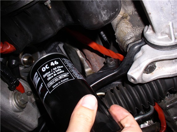
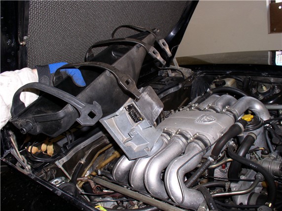
Next in order was the starter wiring harness. Just a 10MM bolt here...
Then I installed the oil filter
The sway bar was next. I only tightened these until they were snug. Again, I read that leaving these un-torqued until the car settles is better. I just replaced the frame bushings last month but still want to lubricate them. I didn't have time to find bushing lube (WSM recommended MolyKote U - aka dry graphite molybdenum disulphide - THANKS Wally for the fancy name! - I love asking for this stuff at the local auto parts store - I just get blank stares ) I will find a supplier soon and lube them up next time they are out - which won't be long - I'm sure.
Then I torqued the 19MM stabilizer link bolts at the stabilizer bar - 62ftlb
Next I torqued the 19MM lower shock mount to Lower Control Arm and stabilizer link Bolt - 62ftlb
Then I replaced the air box and hooked up the air filter and air tubes.
All done underneath....
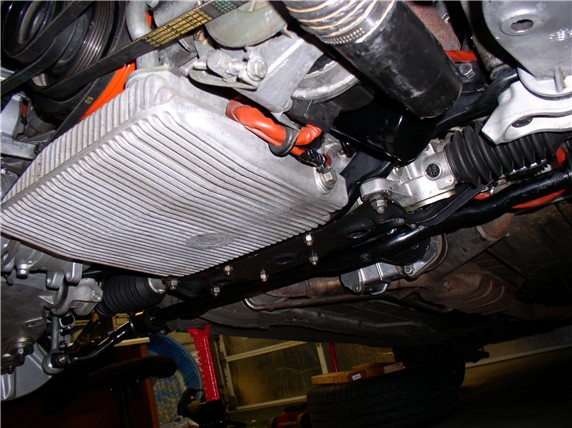
At this point, I would have put the tires back on and lowered the car, put the engine cross brace back on, topped off the oil, and started it up. But I wanted to check a couple other things while the car was in the air - the flex plate tension (since I effectively raised the engine 1/2" with the new mounts) and the crank shaft end play - more on that later.
After taking the car for a drive to let the suspension settle, I brought it back and drove it up on ramps and did the final torque on the Lower Control Arm rear mounts - 19MM and they are torqued to 88ftlb. Also torqued the stabilizer frame bushing bolts - 17MM torqued to 33ftlb. Took a final drive and DONE! and WOW...I like the new mounts!!
THANKS to all that posted on doing this job before - I learned alot before even turning a wrench on this one ....and thanks to Pirtle for documenting the procedure!
Next project is the leaking Transmission and torn CV boots on the rear axles...
Then I installed the oil filter
The sway bar was next. I only tightened these until they were snug. Again, I read that leaving these un-torqued until the car settles is better. I just replaced the frame bushings last month but still want to lubricate them. I didn't have time to find bushing lube (WSM recommended MolyKote U - aka dry graphite molybdenum disulphide - THANKS Wally for the fancy name! - I love asking for this stuff at the local auto parts store - I just get blank stares
) I will find a supplier soon and lube them up next time they are out - which won't be long - I'm sure.Then I torqued the 19MM stabilizer link bolts at the stabilizer bar - 62ftlb
Next I torqued the 19MM lower shock mount to Lower Control Arm and stabilizer link Bolt - 62ftlb
Then I replaced the air box and hooked up the air filter and air tubes.
All done underneath....
At this point, I would have put the tires back on and lowered the car, put the engine cross brace back on, topped off the oil, and started it up. But I wanted to check a couple other things while the car was in the air - the flex plate tension (since I effectively raised the engine 1/2" with the new mounts) and the crank shaft end play - more on that later.
After taking the car for a drive to let the suspension settle, I brought it back and drove it up on ramps and did the final torque on the Lower Control Arm rear mounts - 19MM and they are torqued to 88ftlb. Also torqued the stabilizer frame bushing bolts - 17MM torqued to 33ftlb. Took a final drive and DONE! and WOW...I like the new mounts!!
THANKS to all that posted on doing this job before - I learned alot before even turning a wrench on this one
....and thanks to Pirtle for documenting the procedure! Next project is the leaking Transmission and torn CV boots on the rear axles...
 12-10-2007, 01:03 AM
#50
Three Wheelin'
Thread Starter
Join Date: Sep 2007
Location: Ridgecrest, California
Posts: 1,363
Likes: 0
Received 146 Likes
on
30 Posts
[/ATTACH]
Chris,
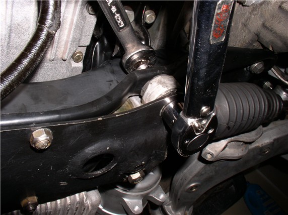
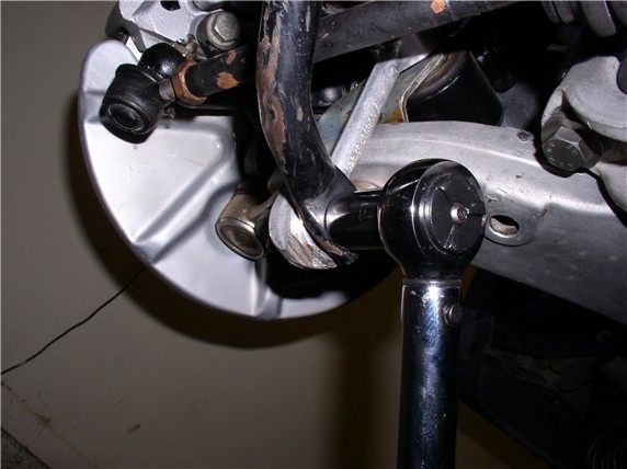
Yes I have some pics from when I was doing the suspension last month...here's the passenger side
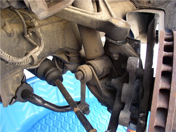
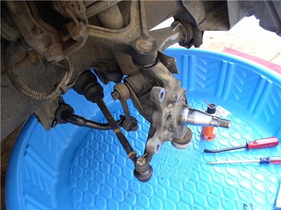
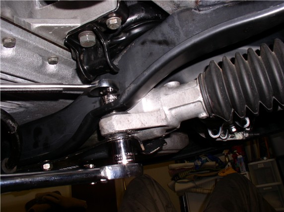
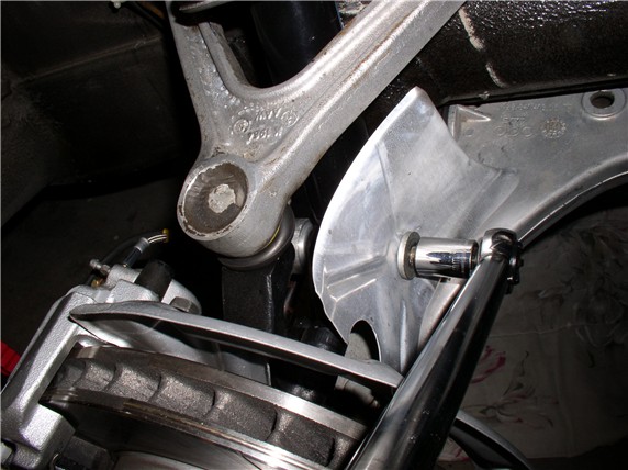
Here's a pic of the driver's side...
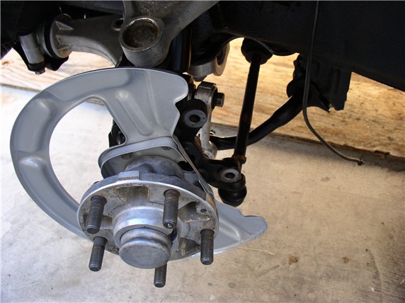
Passenger side again...
I hope these help...if not, let me know and I can take a new pic....
Yes I have some pics from when I was doing the suspension last month...here's the passenger side
Here's a pic of the driver's side...
Passenger side again...
I hope these help...if not, let me know and I can take a new pic....
12-10-2007, 05:43 AM
#51
Under the Lift
Lifetime Rennlist
Member
Lifetime Rennlist
Member
EXCELLENT finish, Dwayne. The lower control arm torque procedure - I don't think that's in Pirtle, so that means you did your homework with the WSM too. BTW, there is some slop in the lower control arm mount locators, so it is possible the alignment is off.
 12-10-2007, 10:23 AM
#53
Three Wheelin'
Thread Starter
Join Date: Sep 2007
Location: Ridgecrest, California
Posts: 1,363
Likes: 0
Received 146 Likes
on
30 Posts
Right on, Bill, about the LCA locators! I noticed the play when reinstalling and thought about the alignment impact. The car has never had a proper four-wheel alignment since I've had it so I'm planning on a "real" alignment after I complete some rear-end work next. Good note...THANKS!
12-10-2007, 10:27 AM
#54
Craic Head
Lifetime Rennlist
Member
Lifetime Rennlist
Member
You do nice work.
I did the MMs and the pan gasket at the same time and the most time consuming part was the cleaning. Would it be too forward to say I like your undercarriage?
Keep up the good work and the detailed posts!
12-10-2007, 10:44 AM
#55
Three Wheelin'
Thread Starter
Join Date: Sep 2007
Location: Ridgecrest, California
Posts: 1,363
Likes: 0
Received 146 Likes
on
30 Posts
After completing the MM change out but while the car was still in the air, I decided to check the crank end play and flex plate tension - I haven't noticed anything unusual but wanted to try it since I was in there. So for those that were waiting, here's a few pics:
After disconnecting the exhaust "Y" pipe from the exhaust manifold and disconnecting the air tube nut, I lowered the exhaust pipes and catalytic converter enough to get at the 6 bolts holding the lower bellhousing cover. Be careful to watch the O2 sensor wires to make sure they don't bind/pull out. With the cover off, I looked at the drive shaft clamp and needed to rotate the engine (clockwise) so I could get at the allen bolt to loosen it. I did this by grabbing the flywheel (with gloves on) and rotating the engine.
I marked the shaft and clamp edge with a marker so I could see if there is any movement on the shaft when I loosen the bolt. Then I loosened the bolt - and nothing happened. No movement. So I thought it might be sticking. I pressed gently on the clamp with a prybar and could see the clamp sliding back and forth on the driveshaft so figured it was not sticking. I'm assuming that means there was no tension at the flex plate.
Next I measured the crank end play by using the prybar to lever the flywheel forward toward the engine. Then took a measurement with my digital micrometer - 41.03MM. Then with the micrometer still in place, I levered the flywheel with the prybar gently to the rear and measured the gap - 41.16MM.
I did this several times and came up with the same numbers. Taking the difference, I came up with 0.13MM end play. Now I need to check the WSM for within tolerance and see if it's good. Unfortunately, I don't have this number memorized.
Anyway, just wanted to close the loop on my earlier post. THANKS for reading (and the GREAT comments!)
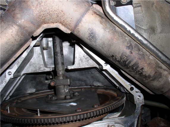
After disconnecting the exhaust "Y" pipe from the exhaust manifold and disconnecting the air tube nut, I lowered the exhaust pipes and catalytic converter enough to get at the 6 bolts holding the lower bellhousing cover. Be careful to watch the O2 sensor wires to make sure they don't bind/pull out. With the cover off, I looked at the drive shaft clamp and needed to rotate the engine (clockwise) so I could get at the allen bolt to loosen it. I did this by grabbing the flywheel (with gloves on) and rotating the engine.
I marked the shaft and clamp edge with a marker so I could see if there is any movement on the shaft when I loosen the bolt. Then I loosened the bolt - and nothing happened. No movement. So I thought it might be sticking. I pressed gently on the clamp with a prybar and could see the clamp sliding back and forth on the driveshaft so figured it was not sticking. I'm assuming that means there was no tension at the flex plate.
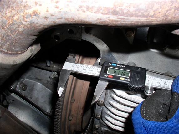
Next I measured the crank end play by using the prybar to lever the flywheel forward toward the engine. Then took a measurement with my digital micrometer - 41.03MM. Then with the micrometer still in place, I levered the flywheel with the prybar gently to the rear and measured the gap - 41.16MM.
I did this several times and came up with the same numbers. Taking the difference, I came up with 0.13MM end play. Now I need to check the WSM for within tolerance and see if it's good. Unfortunately, I don't have this number memorized.
Anyway, just wanted to close the loop on my earlier post. THANKS for reading (and the GREAT comments!)
12-10-2007, 11:00 AM
#56
Craic Head
Lifetime Rennlist
Member
Lifetime Rennlist
Member
Dwayne,
You need to get a set of crossovers and new high-flow cats. They make checking your crank endplay much easier because they are out farther and allow complete access to the lower bell housing.
Of course, that's not the only reason...

You need to get a set of crossovers and new high-flow cats. They make checking your crank endplay much easier because they are out farther and allow complete access to the lower bell housing
. Of course, that's not the only reason...
12-10-2007, 01:58 PM
#57
Shameful Thread Killer
Rennlist Member
Rennlist Member
12-10-2007, 02:28 PM
#58
Under the Lift
Lifetime Rennlist
Member
Lifetime Rennlist
Member
Dwayne:
0.13mm endplay is very low - factory spec is 0.2mm and wear limit is 0.4mm.
You did it the easy way, as Tony shows in the link in the LATE EDIT at the beginning of my write-up.
https://rennlist.com/forums/showthre...hlight=endplay
You should have the early TT shaft with the shims and circlip infront of the flywheel that prevents rearward TT shaft movement through the clamp. Most of us suspect that eliminates accumulation of forward pressure on the fleplate and excessive thrust bearing wear. I've installed the early shaft on later model 928s when it came to replacement time.
Last edited by Bill Ball; 12-13-2007 at 02:18 PM.
12-10-2007, 03:42 PM
#60
Dwayne,
Great pictures and write up. Done al this myself last summer but spend a little more time. Checked my flexplate and crank this weekend and came up with 0.24 mm endplay. Good to see al this work and especialy the pictures and sharing them with the others!
Robert 1994 GTS midnightblue the Netherlands
Great pictures and write up. Done al this myself last summer but spend a little more time. Checked my flexplate and crank this weekend and came up with 0.24 mm endplay. Good to see al this work and especialy the pictures and sharing them with the others!
Robert 1994 GTS midnightblue the Netherlands