

DEVEK - SUPERMODEL Tech Session and Gathering, March 26-27
 04-08-2005, 01:22 PM
#331
Under the Lift
Lifetime Rennlist
Member
Lifetime Rennlist
Member
The two smaller tubes are 2.5 inch. They fit through the round opening on the fan shroud (3 inch or larger would not)and must flatten as the horn does when you pull them through.
 04-08-2005, 04:20 PM
#332
Burning Brakes
Originally Posted by Jim_H
Derek, I forgot, it was you with the autorotor. Be careful under 3000 R's until you get that thing dynoed.
 04-08-2005, 04:36 PM
#333
Addict
Rennlist Member
Rennlist Member

Join Date: Mar 2002
Location: Pacifica, CA--Land of Fog
Posts: 628
Likes: 0
Received 0 Likes
on
0 Posts
Hey folks, questions:
How can I run the boost vaccum line into the car from the manifold w/o drilling? I do not have the funky hole that Bill has near the intensive washer reservoir.
Do you hook up the A/F meter to the 02 sensor wire near the fuse panel?
Do I need the belly pan to be off to do these thingss? (asking Devek to put it back on after oil change if I don't).
Please advise ASAP
04-08-2005, 04:45 PM
#334
Three Wheelin'
Join Date: Nov 2003
Location: Los Angeles, CA
Posts: 1,577
Likes: 0
Received 0 Likes
on
0 Posts
Originally Posted by Seth W
Hey folks, questions:
How can I run the boost vaccum line into the car from the manifold w/o drilling? I do not have the funky hole that Bill has near the intensive washer reservoir.
Do you hook up the A/F meter to the 02 sensor wire near the fuse panel?
Do I need the belly pan to be off to do these thingss? (asking Devek to put it back on after oil change if I don't).
Please advise ASAP
How can I run the boost vaccum line into the car from the manifold w/o drilling? I do not have the funky hole that Bill has near the intensive washer reservoir.
Do you hook up the A/F meter to the 02 sensor wire near the fuse panel?
Do I need the belly pan to be off to do these thingss? (asking Devek to put it back on after oil change if I don't).
Please advise ASAP
To be 100% honest, once you know how much boost you're running, you don't need a gauge. Its not like your car is ever going to "overboost"... it just isn't possible. The only thing that could happen is your belt would slip a little and I doubt you'll be starring at your boost gauge (which isnt' very accurate) when you're putting down over 400rwhp at 5500rpms where the belt may slip. I personally don't run a boost gauge in my car.
Yes, the A/F meter hooks to the o2 sensor. Make sure you've got a fresh O2 sensor in there (might as well change it while you can if it is old). I believe you want to tap the black wire. If you tap it on the O2 sensor side, you "permanent" tap will only be done to the O2 sensor and not the car's harness (since i know how you are about those things).
You will only need the belly pan off if you decide to route the vacuum line through the LH grommet.
04-08-2005, 05:02 PM
#335
Inventor
Rennlist Member
Rennlist Member
Originally Posted by Seth W
How can I run the boost vaccum line into the car from the manifold w/o drilling? I do not have the funky hole that Bill has near the intensive washer reservoir.
 04-08-2005, 05:07 PM
#336
Under the Lift
Lifetime Rennlist
Member
Lifetime Rennlist
Member
Seth:
The O2 is easy. Other than the black sensor wire, it needs dimmer power - I clipped into the wire that feeds the clock light. We could even use a piggyback spade there - no cutting into the wire. Also, it needs ground and switched power - both available from the cigarette lighter wires. I mounted the gauges using the plate Andy provide which replaces the ashtray/lighter - simple drop in. Wires will be totally hidden.
The IC pump also needs switched power. We should feed that wire through the LH harness grommet and find switched power there or again at the cig lighter.
I think you have enough of the hard plastic boost line to feed down through the LH harness grommet and feed up along the side panel on the center console to the cig area where the gauge should be mounted, as I mentioned.
See you at 4PM at DEVEK?
The O2 is easy. Other than the black sensor wire, it needs dimmer power - I clipped into the wire that feeds the clock light. We could even use a piggyback spade there - no cutting into the wire.
Also, it needs ground and switched power - both available from the cigarette lighter wires. I mounted the gauges using the plate Andy provide which replaces the ashtray/lighter - simple drop in. Wires will be totally hidden.The IC pump also needs switched power. We should feed that wire through the LH harness grommet and find switched power there or again at the cig lighter.
I think you have enough of the hard plastic boost line to feed down through the LH harness grommet and feed up along the side panel on the center console to the cig area where the gauge should be mounted, as I mentioned.
See you at 4PM at DEVEK?
Last edited by Bill Ball; 04-08-2005 at 05:49 PM.
04-08-2005, 05:18 PM
#337
Range Master
Pepsie Lite
Lifetime Rennlist
Member
Pepsie Lite
Lifetime Rennlist
Member

Seth, my notes from my gauge install:
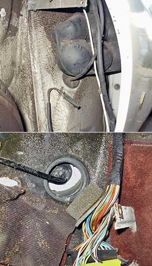
The AFM gauge has a wire that needs to be connected to the CO2 sensor on the signal line. The 3 wire CO2 sensor has 3 wires, 2 white and one black. The black wire is the signal wire. There is a connector to the right side of the hump, behind the base of the fuse panel. Lift the door of the fuse panel and prop it open. Remove the base of the fuse panel. Look for a round black connector lying on the floor at the bottom left of the fuse panel. Dissconnect the connector. Remove the consol panel on the passenger side and thread the signal wire down to the lower laft hand of the fuse panel. On the sensor side of the connector, pull the rubber covering back from the connector, exposing the 3 wires. Cut the black one, strip back some insulator and splice the signal wire to the AFM gauge into this line. Replace the rubber covering and reconnect the connectors.
On my install, there was not any place on the left fire wall I felt comfortable threading the vacuum line through, all options seemed either poorly located or the line potentially interfered with. I drilled a hole in the fire wall just below the intensive washer reservoir, grometed it and ran the line through it, then across to the center console to the gauge. My notes: The vacuum line needs to be fed through the fire wall. One convenient place to do this is immediately under the intensive washer reservoir, about an inch back from the front fire wall. Remove the tray under the dash on the drivers side. Remove the drivers side panel on the center consol. Under the dash, with a flashlight look up to the point where the steering column exits the fire wall. As you are laying on your back, the point where you want to run the vacuum hose is just to the laft of the steering column, but not so it interferes with the throttle mechanism. Once you have found this point, remove the intensive washer reservoir and find the same point on the top of this location. Take a small drill bit and drill through the fire wall with a hole big enough to pass the vacuum line through, plus a gromet. After you make the connections at the gauge and the vacuum line leading to the FMU, put some calking around the line where it exits the fire wall., on both sides.
I also used the cigar lighter circuit to power up my intercooler pump and backlight my guages. My notes: After you have removed the ash tray you will see three wires leading to the area. One wire was for the ashtray light. This wire is a good place to get power fot the backlights in the boost gauge. One wire is a brown wire, (ground) which is a good place to ground the AFM gauge and boost gauge backlighting wire(s). The third is a hot lead to the cigar lighter. In the 89 GT this lead is switched through the ignition and so is a great power source gauge (AFM) and the switch for the AWIC pump. Make sure all your power feed connections are insulated with electricians tape or some like material. If you use the hot lead for the cigar lighter for the gauge and pump power feeds, replace the 25 amp fuse (#2 fuse) with the 7.5 amp fuse you took out of the panel for the air flap actuators. This way you are not over fused for the new pump application.
04-08-2005, 05:23 PM
#338
Three Wheelin'
Join Date: Nov 2003
Location: Los Angeles, CA
Posts: 1,577
Likes: 0
Received 0 Likes
on
0 Posts
One more thing to add....
Depending on your A/F gauge, if you have one with an illuminated face, you can tee that into the power line for the pump. This way, as long as that light is on, you know the pump is at least getting power (doesn't really tell you how its performing, but its an extra indicator).
I've never heard of a pump failure, but given its importance... you might as well get some kind of indicator light going.
04-08-2005, 05:31 PM
#339
Banned
Join Date: May 2001
Location: The Great Northwest
Posts: 12,264
Likes: 0
Received 3 Likes
on
3 Posts
Bill, what do you mean by IC pump needing switched power. I didn't think this was an IC set up but I guess it must be? Now that I am writing this I remeber Seth had his fender liner off, = washer resevoir = IC, duh. We (Mike) used a 15amp fuse for the IC pump.
Jim
The IC pump also needs switched power. We should feed that wire through the LH harness grommet and find swiched power there or again at the cig lighter.
?
Jim
Originally Posted by Bill Ball
The IC pump also needs switched power. We should feed that wire through the LH harness grommet and find swiched power there or again at the cig lighter.
?
04-08-2005, 05:45 PM
#340
Under the Lift
Lifetime Rennlist
Member
Lifetime Rennlist
Member
The pump should run when the ignition is on, so the cig lighter feed is a good source as it is only on when the ignition is on in MOST 928s. We need to check that in Seth's car. Should have no problem powering the gauges and IC pump from that feed. If the pump needs more juice we'll find a better "switched" feed off the panel.
04-08-2005, 05:52 PM
#342
Range Master
Pepsie Lite
Lifetime Rennlist
Member
Pepsie Lite
Lifetime Rennlist
Member
Originally Posted by Bill Ball
The pump should run when the ignition is on, so the cig lighter feed is a good source as it is only on when the ignition is on in MOST 928s. We need to check that in Seth's car. Should have no problem powering the gauges and IC pump from that feed. If the pump needs more juice we'll find a better "switched" feed off the panel.
The cigar lighter circuit is fused at 25 amp, there is more than enough power there.......actually too much......As I posted in my notes, I re-fused to 7.5 amps.
04-08-2005, 07:18 PM
#345
Addict
Lifetime Rennlist
Member
Lifetime Rennlist
Member
I have my IC pump wired to the power windows . If i shut the car down like i do in the staging lanes at the drag strip, the pump will still run.
The pump shuts off once the doors (a door) is opened. I have it switched to an illuminated blue switch also.
The switch allows me to turn it off if
1) it blows a line and leaks
2) on the way out to the drag strip i can turn my pump of so i don't circulate the water thus preventing heating it when i dont have to.
One of my next things is to add two small fans in front of the HE to allow airflow when stopped.
FYI the best way to add these circuits i have found is to got to pepeboys/autozone and get the "add a circuit" fuse. You dont cut or spice any wires and its fused right away.