When you click on links to various merchants on this site and make a purchase, this can result in this site earning a commission. Affiliate programs and affiliations include, but are not limited to, the eBay Partner Network.
I am working on the CV axles now, but have an immediate question.
I will post the rest of the work soon.
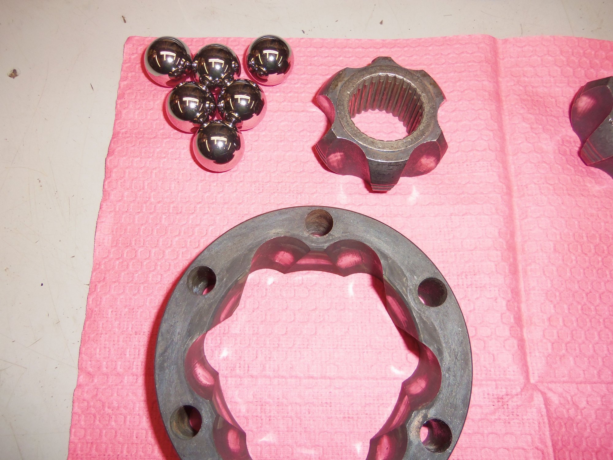
Disassembly and cleaning of the inner CV joints went fine. No real problems. All the races in the body and hub, as well as all the bearing *****, looked great, no abnormal wear.
Except this one...
On the passenger's side CV joint hub, there is what I would call a casting defect in one of the races. It is near the end of the ball travel. The ball obviously has been rolling over it. However, none of the ***** show any wear, scoring, or damage. Rolling a ball through that bearing race, it feels smooth. The ball does not catch on the defect. The defect does not stick up past the surface of the bearing race.
Not sure what to do here. Knee-jerk reaction is to find another hub. However, I am loathe to give up this relatively low mile CV joint. And, the lack of wear on the ***** is throwing me. I don't want to toss this CV joint if I don't have to.
So...what say you?
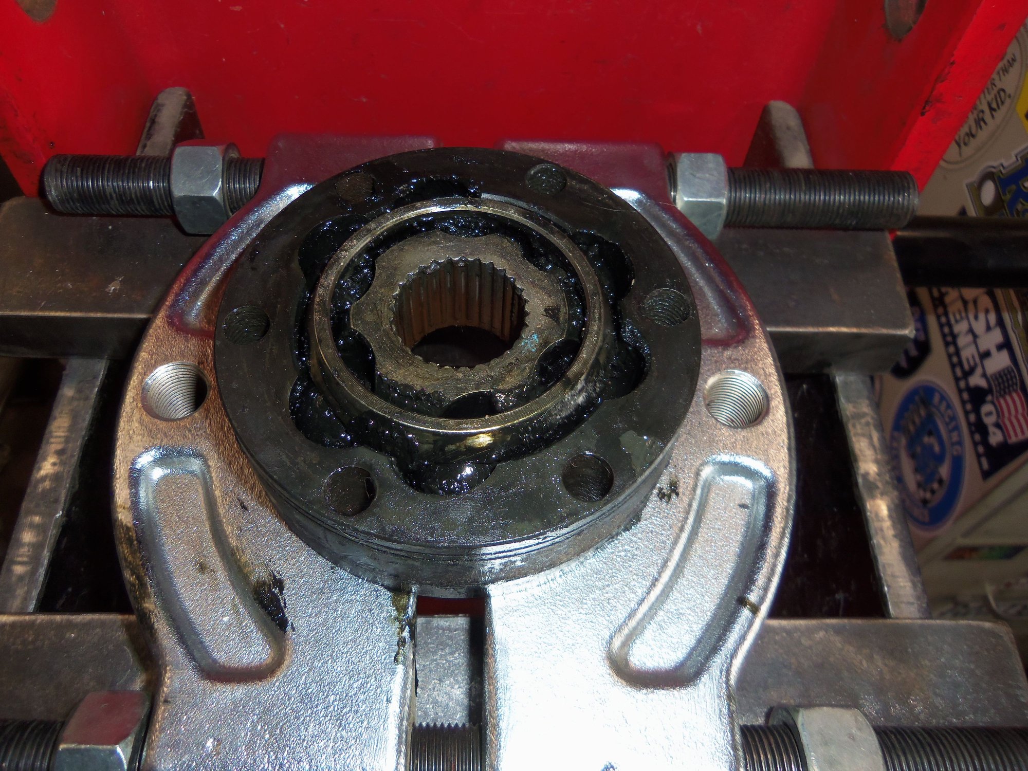
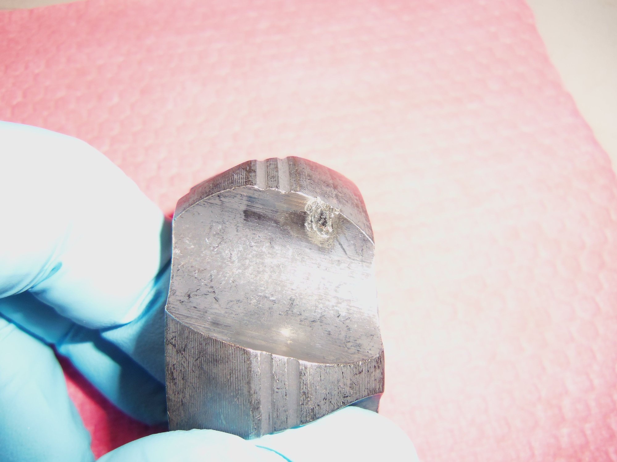
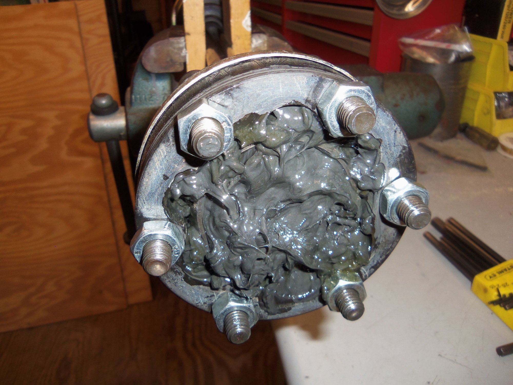
No wear or damage to the bearing *****. All 6 ***** from this CV joint look like this.
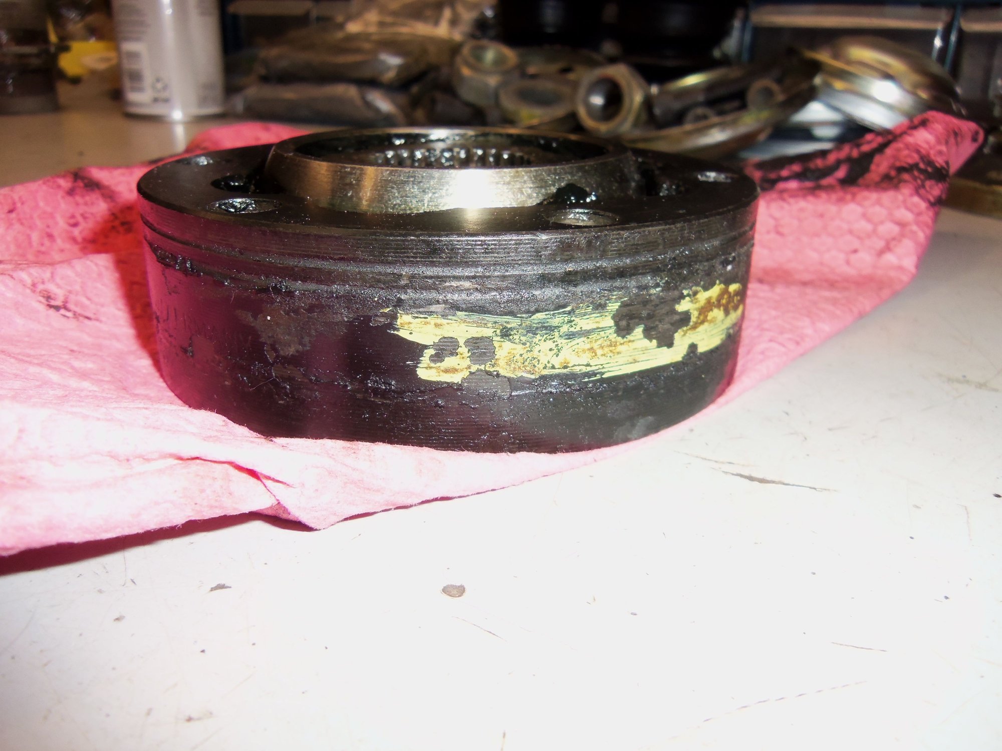
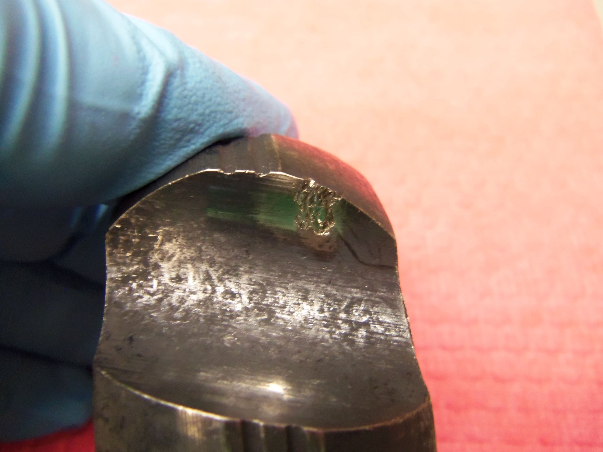
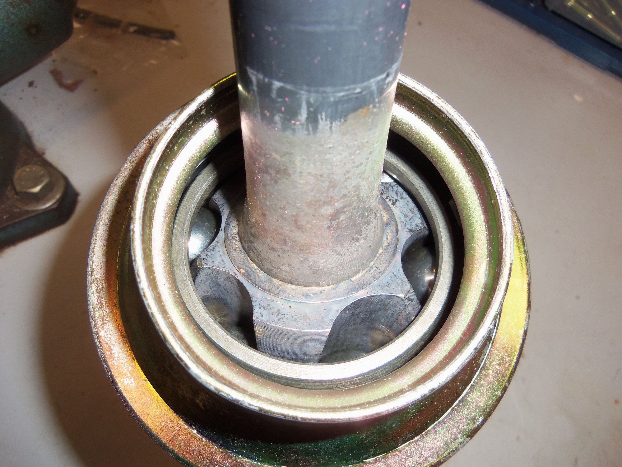
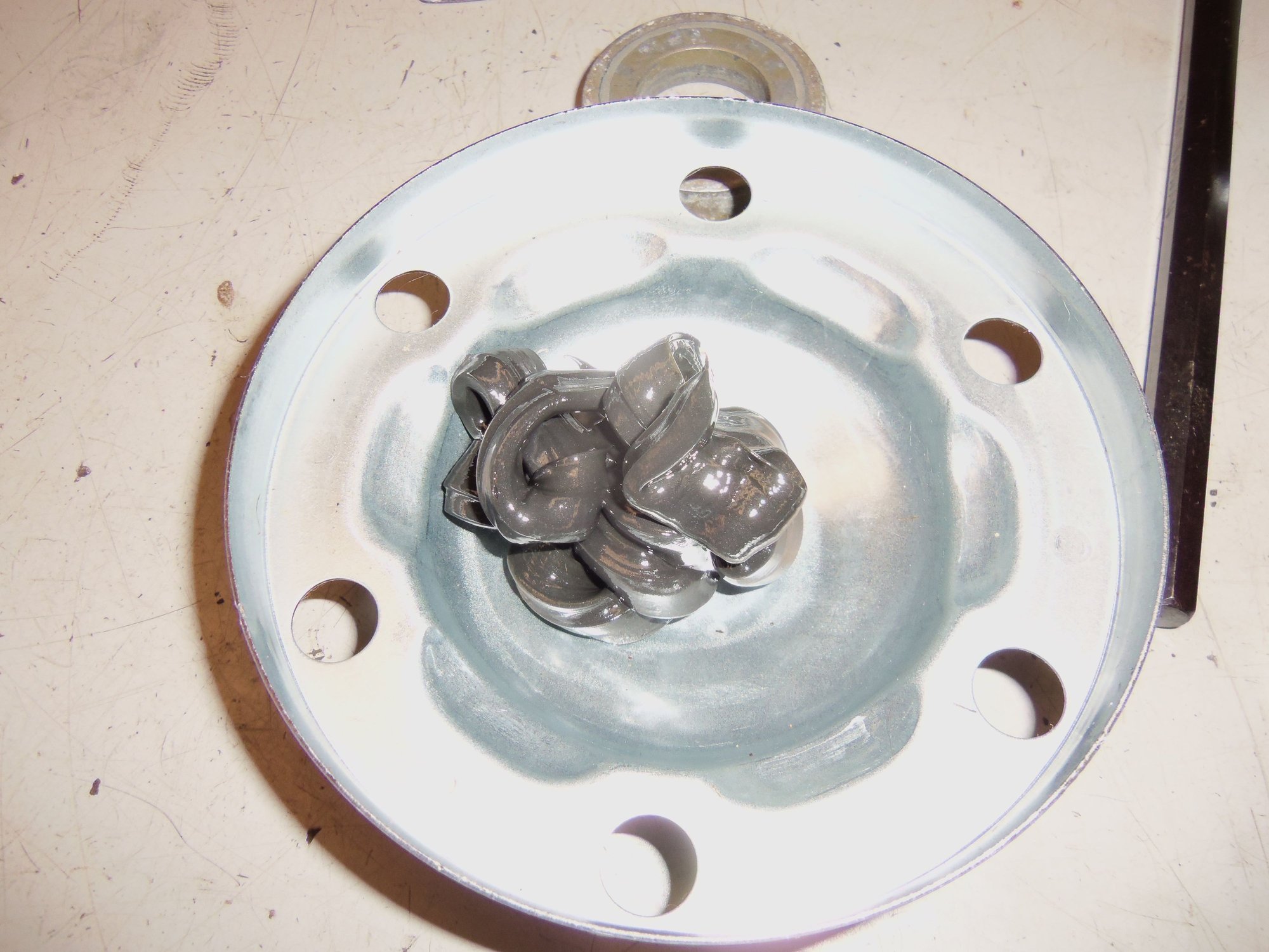
Normal wear in 11 of the 12 bearing race surfaces in this hub.
Seth, that looks very similar to the race wear I found on my 944 a couple of years ago, I'd say it's the beginning of wear on that side and would replace it. I found similar, but more extensive wear on all four races and replaced them all. My experience has been unless your time is very cheap, it's more economical to buy the complete joint.
Sorry I can't find pictures of the failed races, I posted them here in the 944 forum though, I'll see if I can find the post and quote it.
Let me clarify, I will not need another hub, I will need another complete inner CV joint assembly. The *****, hub, and outer body are all matched to each other.
Otto, good link. Thank you for that.
I am going to disassemble the inner CV joint from the Red Witch's original passenger's side axle after FRENZY and go from there...
I have completed the next to last task for the back of the Red Witch. The rear CV axles have been disassembled, cleaned, inspected, lubricated, resealed, and installed!
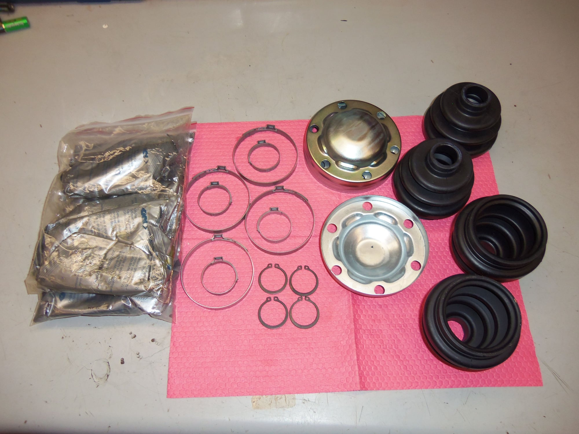
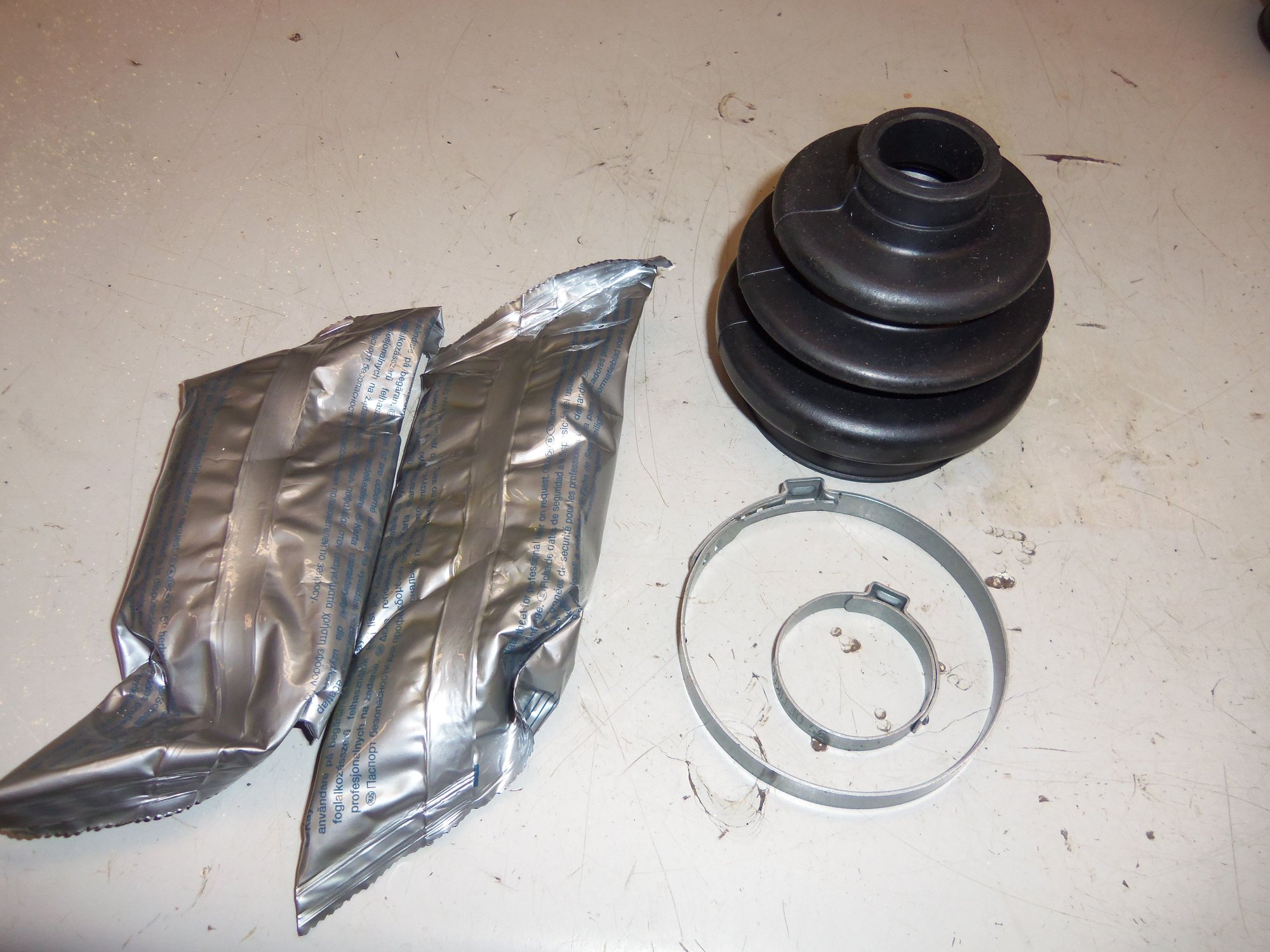
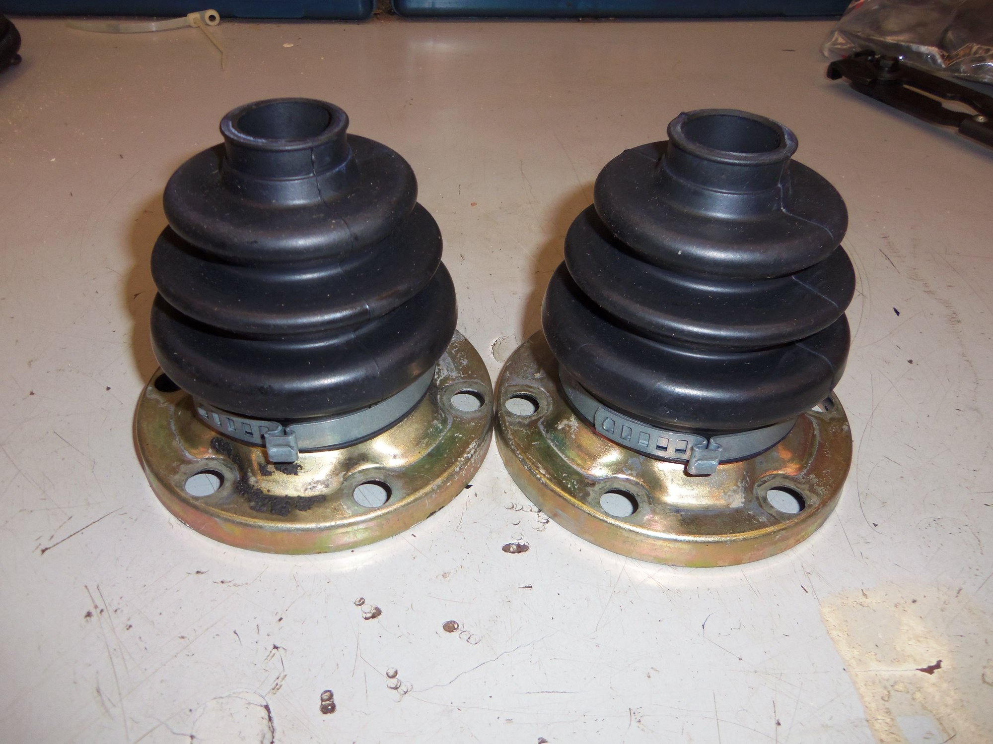
Some time ago, Roger sent me the needed parts for this job: 4 CV boot kits, each containing a boot, large clamp, small clamp, end cap, snap ring, and two packets of grease. The boot kits are part number 928 332 924 02, and are for 1985-95 928s. Only $11.95 each! Less than $50 to do both axles.
Four new CV joint boot kits for 1985-95 928 axles, part number 928 332 924 02.
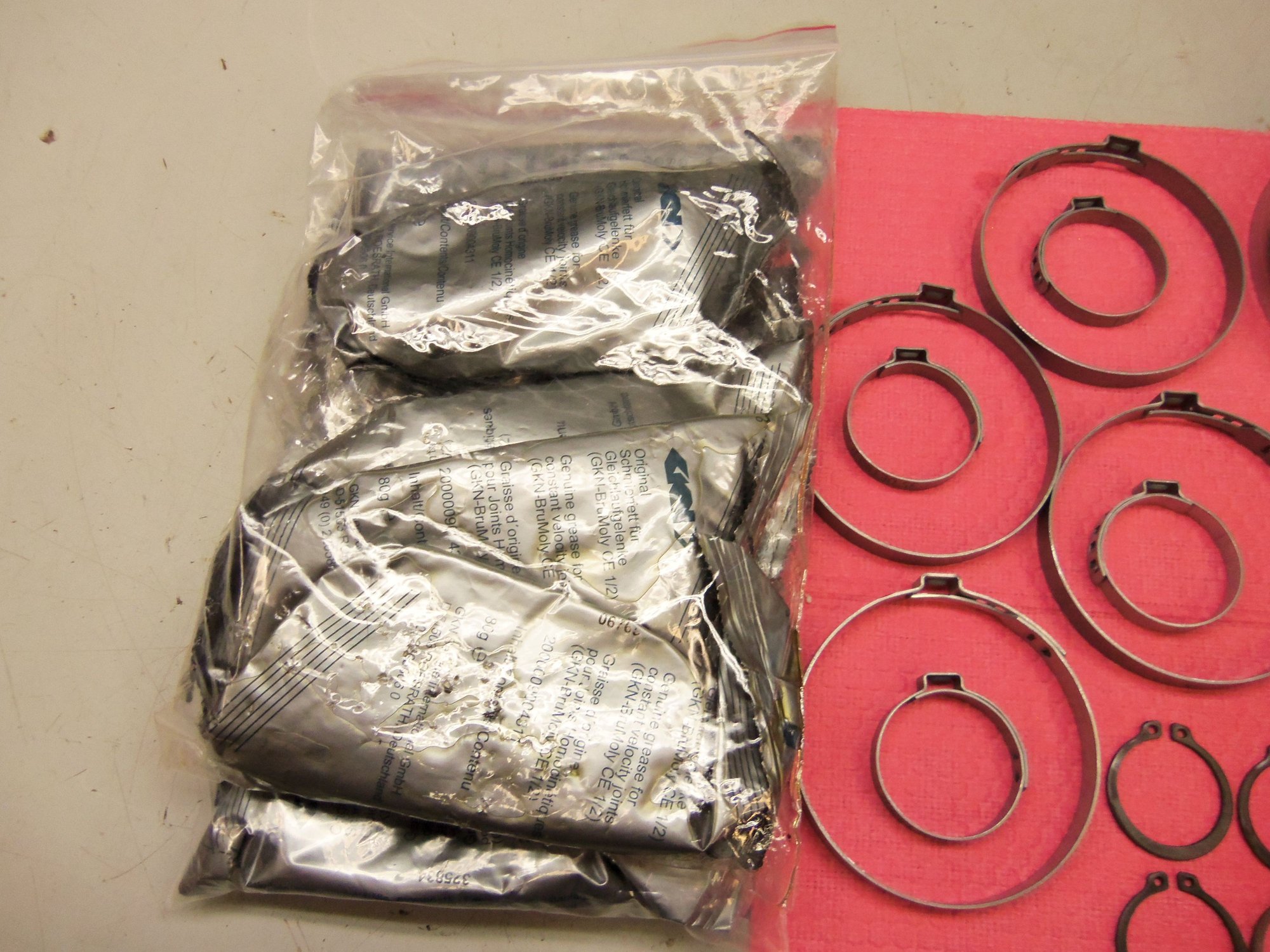
Eight packs of CV joint grease, four large OET clamps, and four small OET clamps.
Four snap rings, four closed end caps, and four boots.
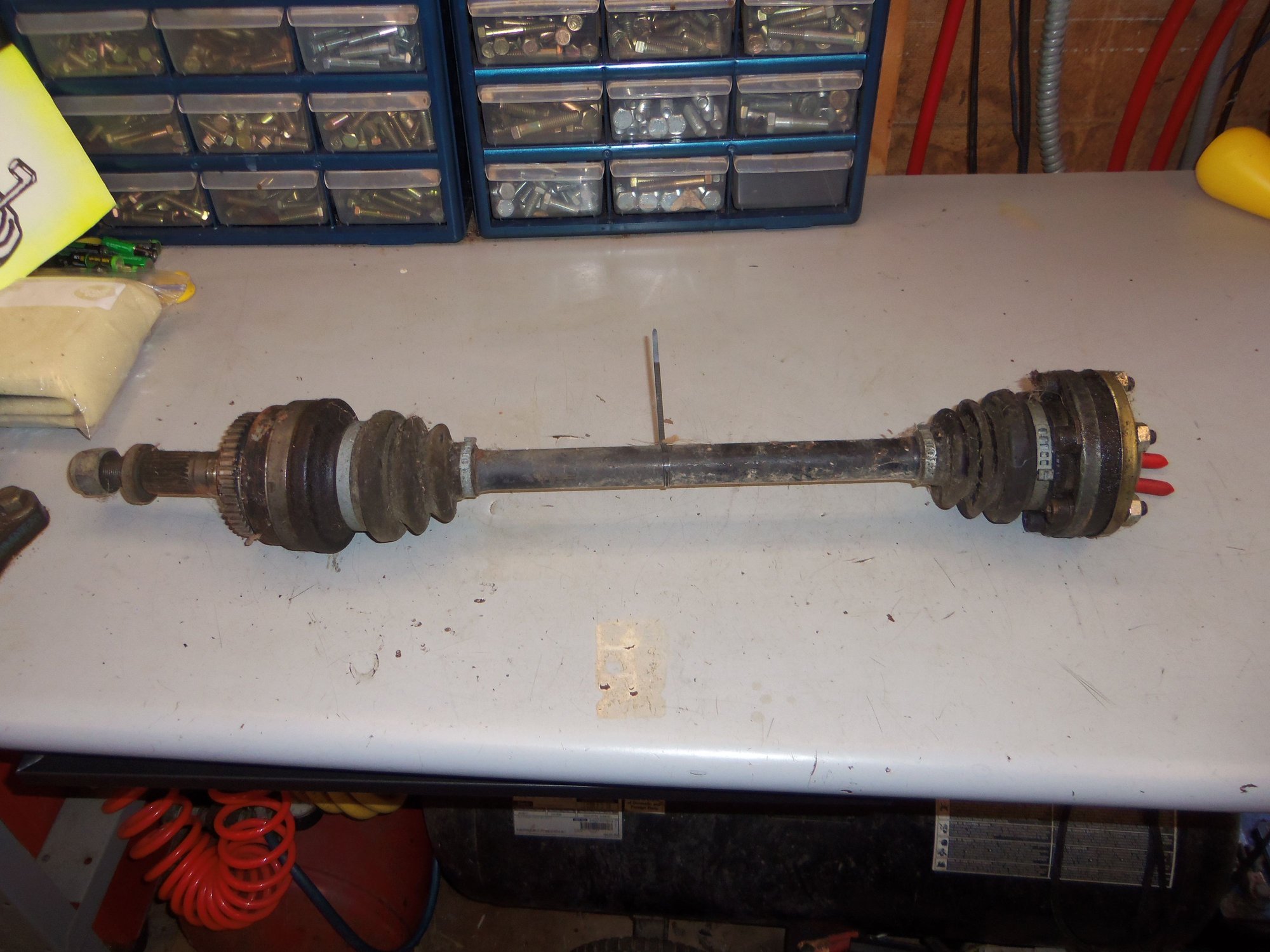
Since they only had a purported 68,*** miles on them, and looked in better physical condition, I went with the CV axles from the donor 1988 S4 rear suspension.
Both axles were covered in dirt and road grime, but had no obvious issues. The hub end splines and threads were in good condition and the ABS tone rings were undamaged.
None of the boots were torn and I felt no dryness or grittiness in any of the CV joints.
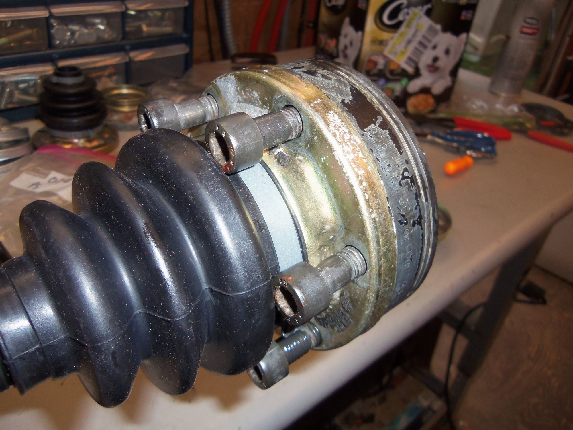
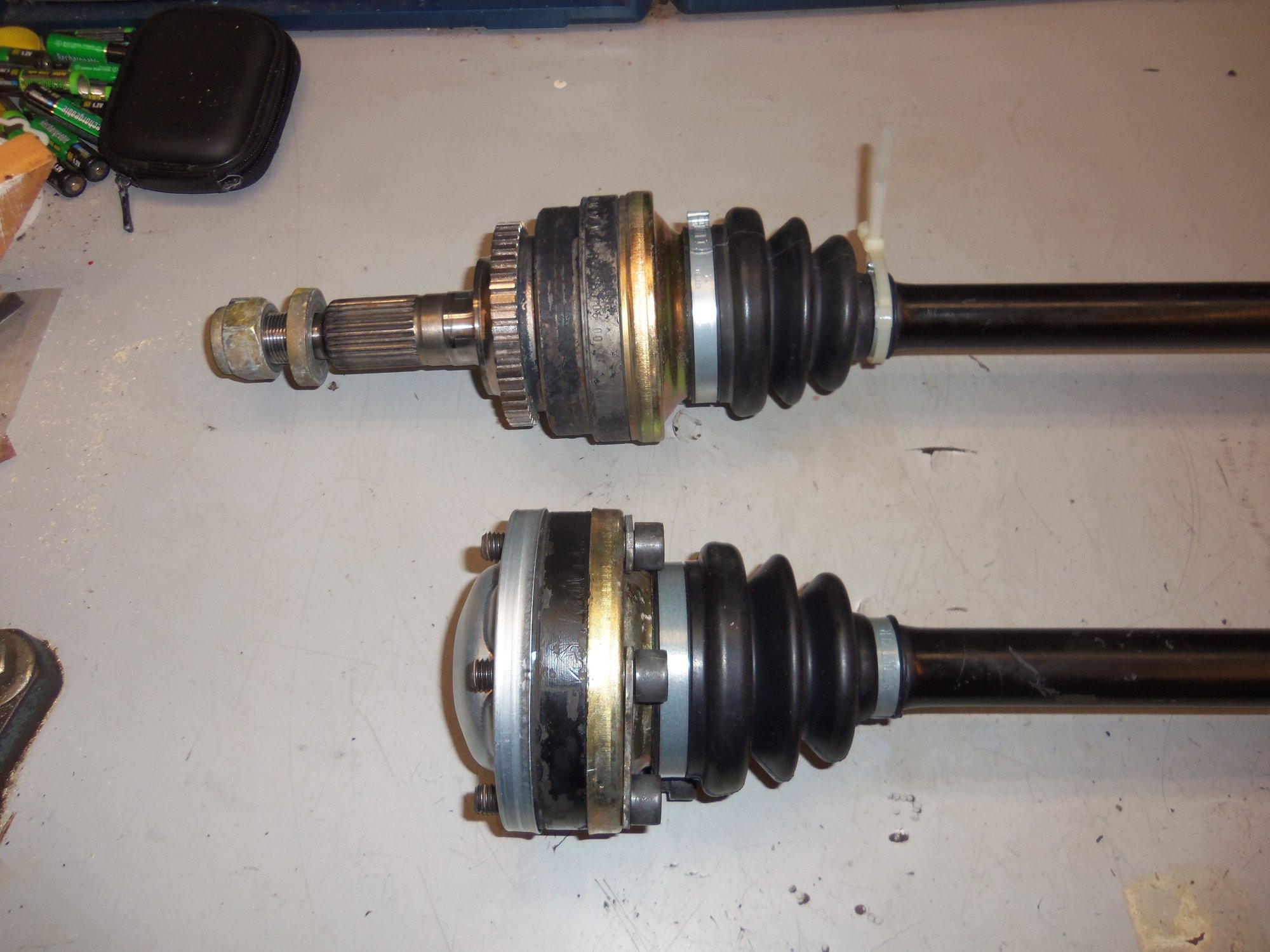
Driver's side CV axle assembly. Note: the following pictures are of the driver's side axle, but are representative of the passenger's side axle as well.
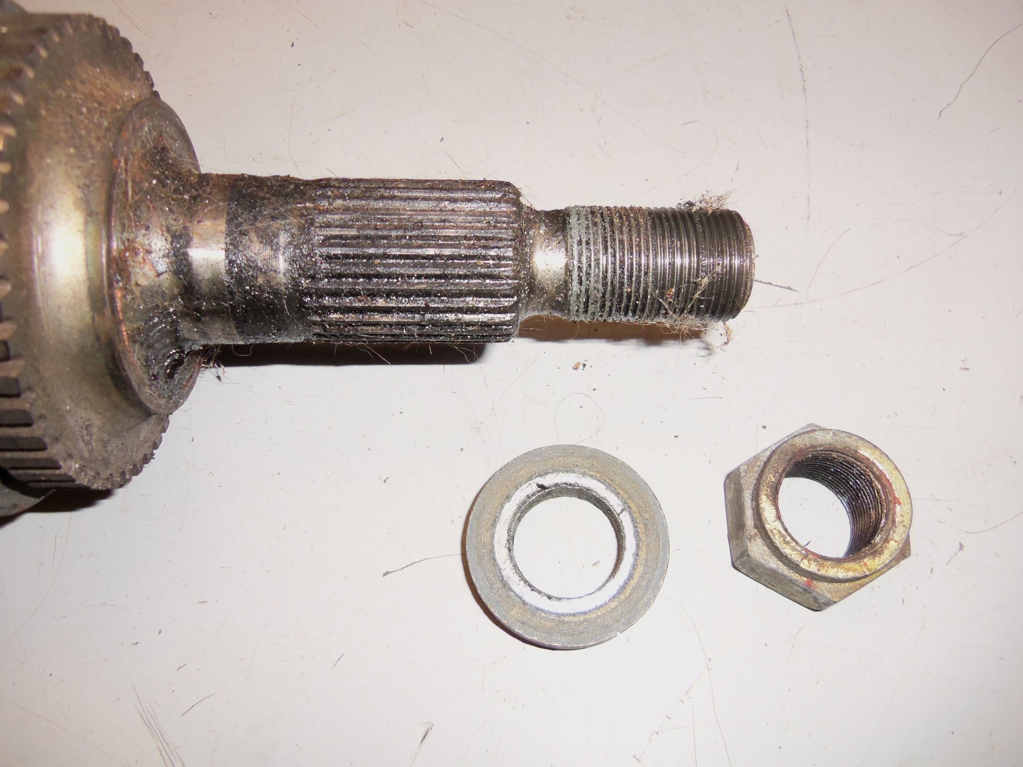
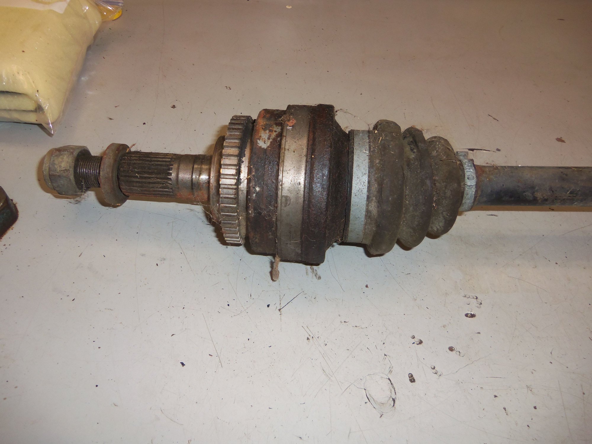
Threads and splines are dirty, but not corroded.
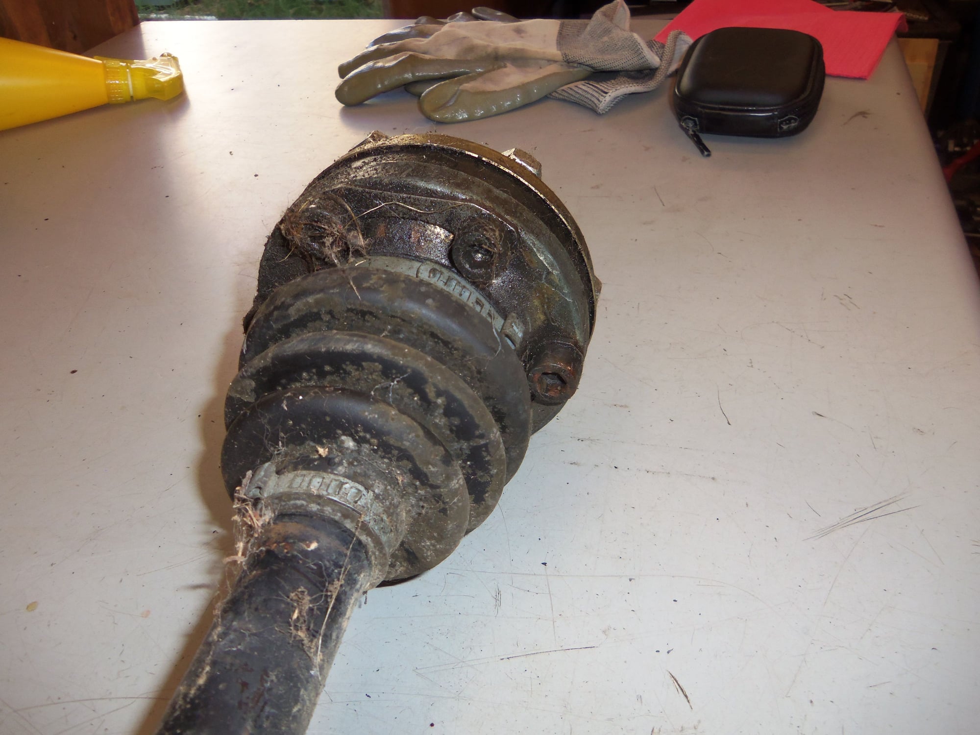
Road grime, but no damage to the boot or inner cap.
Road grime, but no damage to the boot or either cap.
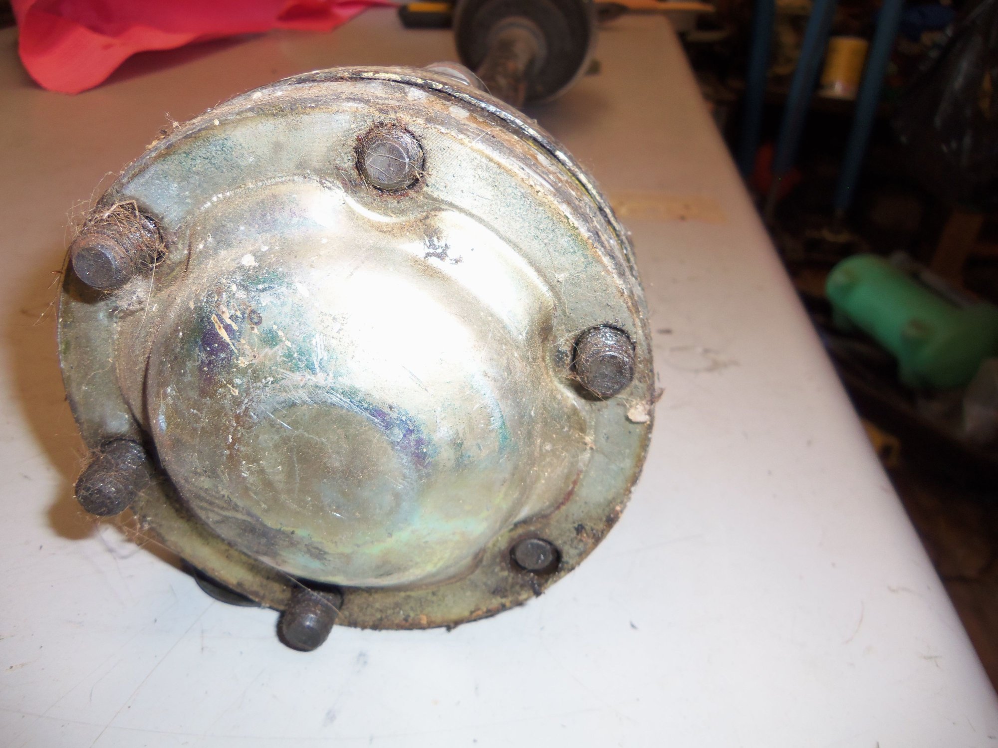
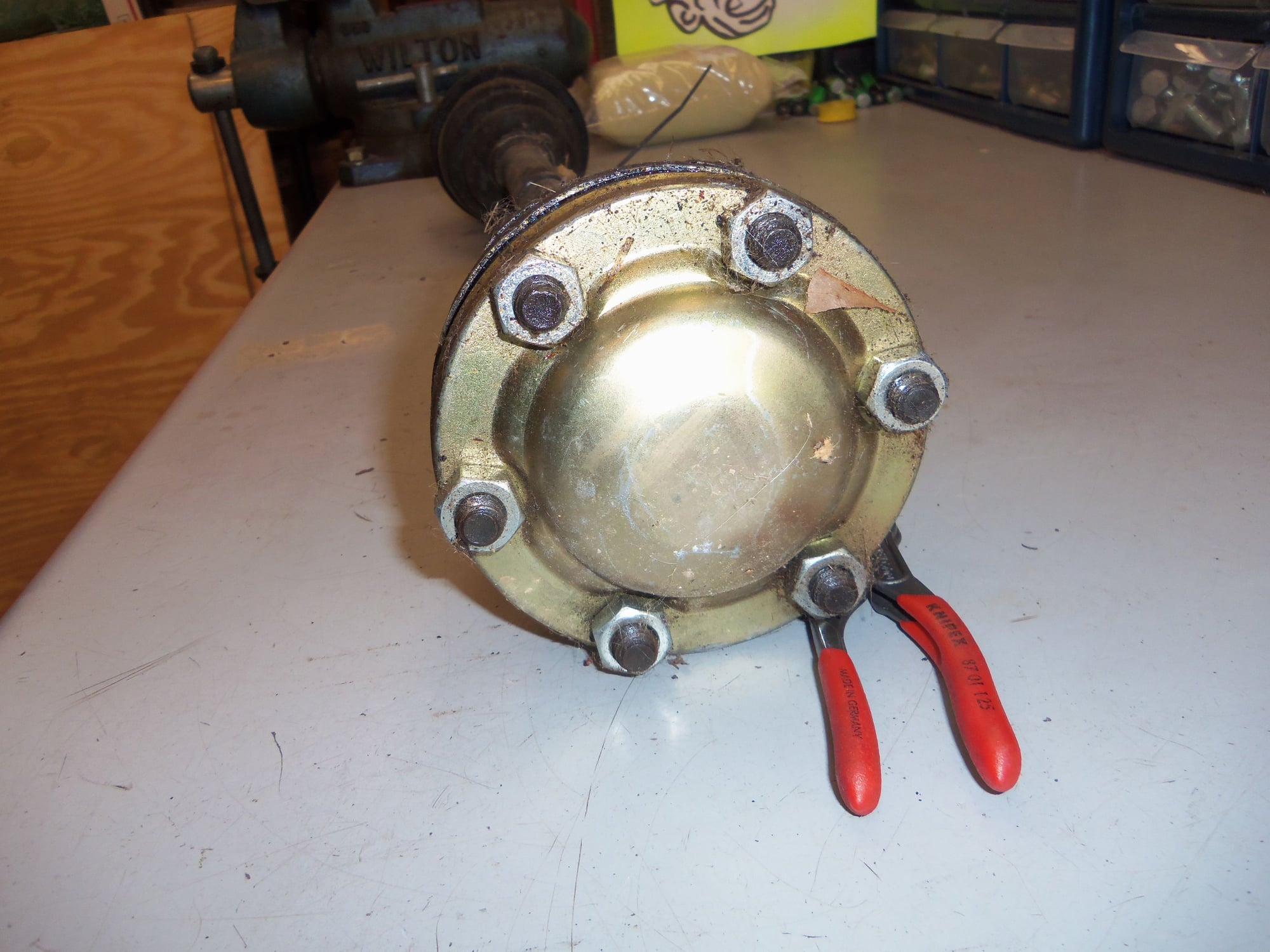
Bolt heads are not damaged.
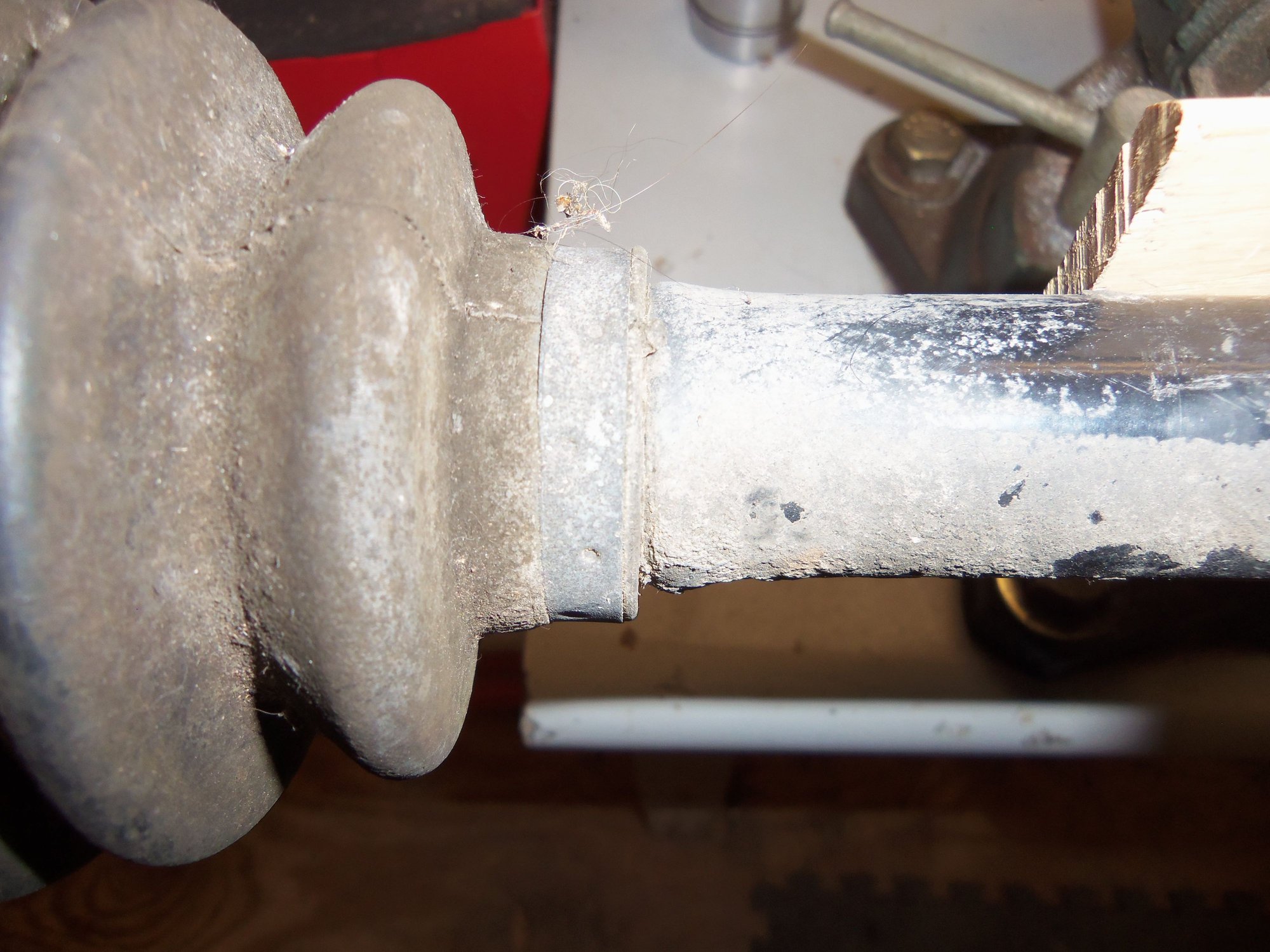
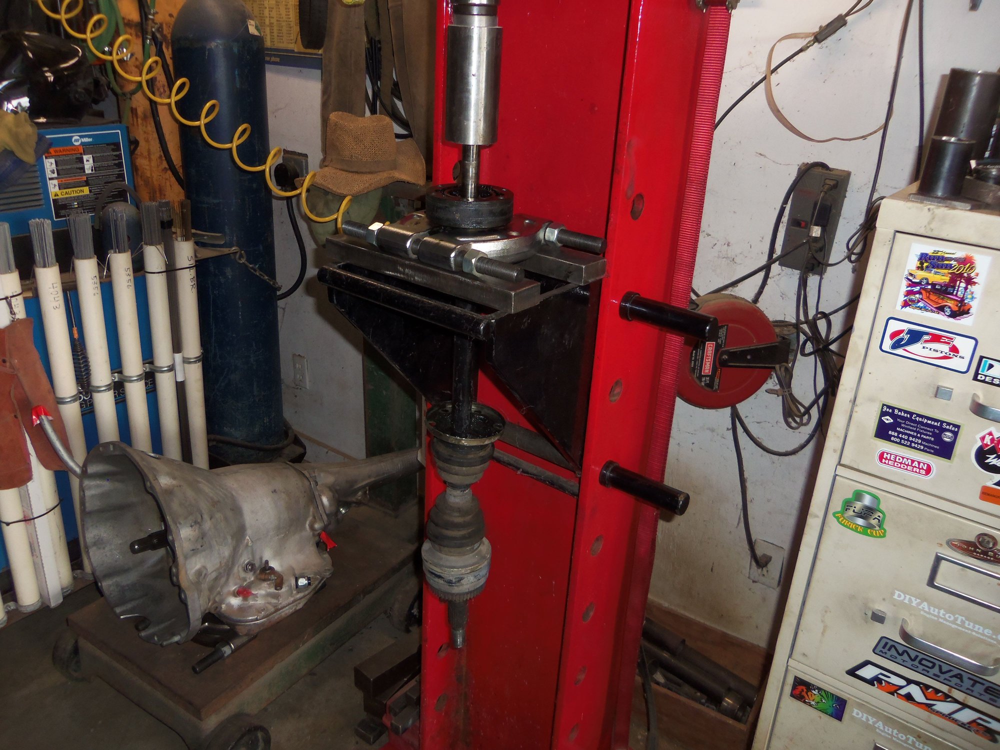
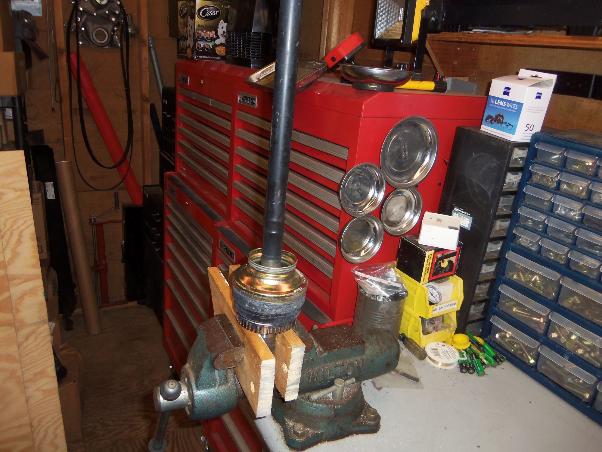
I chucked each axle up in my vise, with wood blocks to prevent marring the axle shafts.
First order of business was to remove the end cap of the inner CV joint. This seemed simple enough. No. I am simple. Which is why I failed to grasp basic physics. More on that in a moment...
The bolts were a bit of a pain to get out because they hit the rubber boots. I had to pivot the CV joint to its limit in away from the bolt I wanted to remove, and then just squeak the bolt head past the boot.
Next was to remove the boot for an inspection of the guts of the inner CV joint. This was a mistake. I was able to unfold the locking tab and remove the large and small clamp, then pull the boot off the spigot of the inner cap. The joint was then quite floppy. Remember this...
I was glad to see plenty of old grease in the joint, and no obvious dirt or corrosion. Moving the joint around revealed no flaws, either. It was interesting to see the ***** and hub move in and out as I pushed and pulled the CV joint on the axle shaft. I have never had a CV joint apart before. Good learning experience.
The end cap was pressed onto the body of the CV joint itself. I figured a few taps with a hammer on a punch and off it would come. Wrong. Dummy.
Remember how I said the joint was floppy? Hitting the punch on the end cap just tilted the body of the CV joint. I was afraid to hit the cap with the joint fully tilted because it acted like the ***** wanted to come out. Bad learning experience.
Eventually, I was able to hold the CV joint enough to land enough hammer blows to get the end cap off. There was old grease inside the end cap, and plenty of old grease in the CV joint.
So far, so good!
I had the same floppy CV joint problems when trying to get the inner cap off. Then I had an 'a-HA!' moment. The boot will stabilize the joint. I put the boot back on the spigot on the inner cap. Ta-DA!. The joint more or less held still while I tapped the cap off.
For the other axle, I left the boot on, tapped the end cap off, then tapped the inner cap off. Much easier.
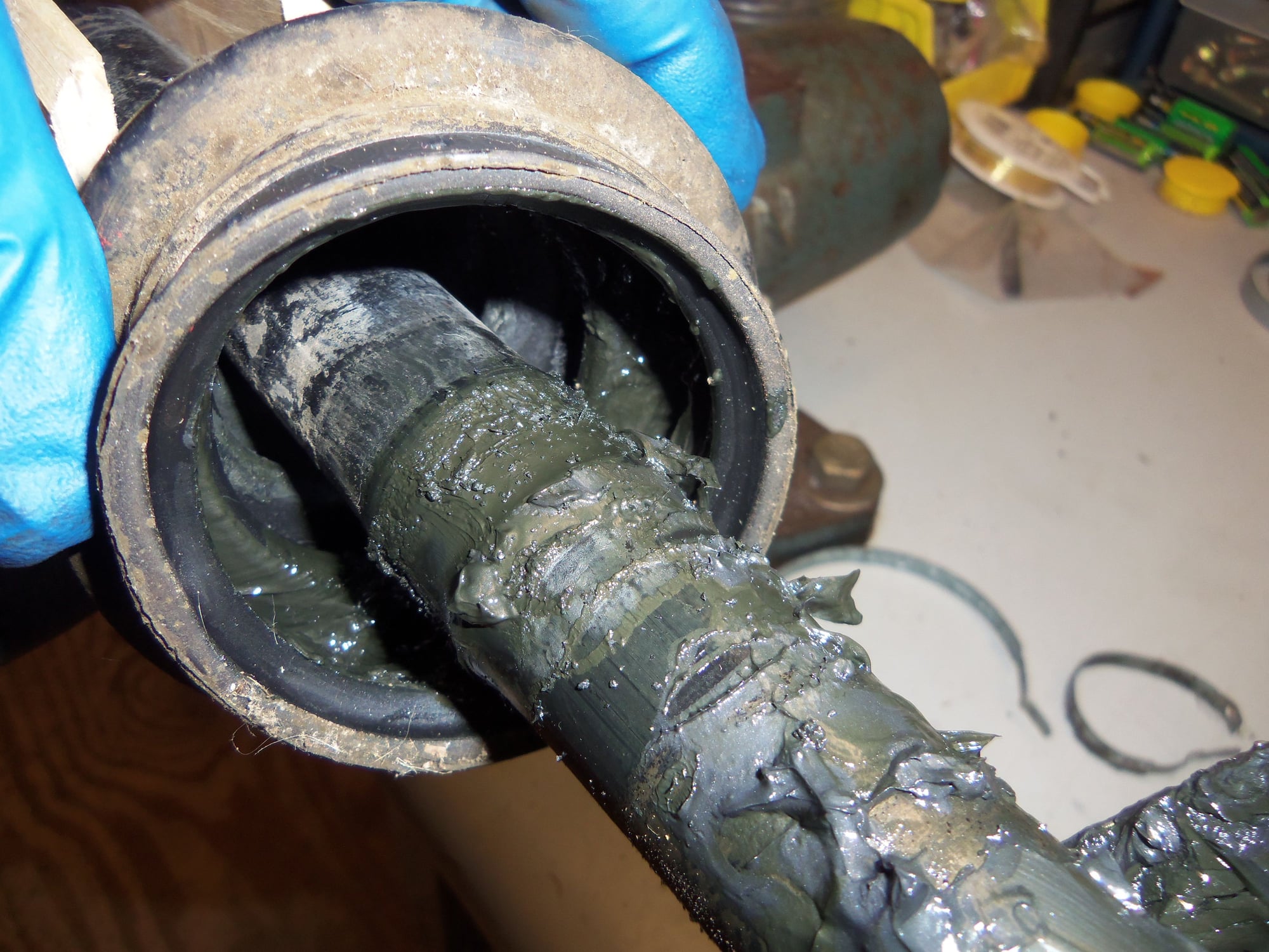
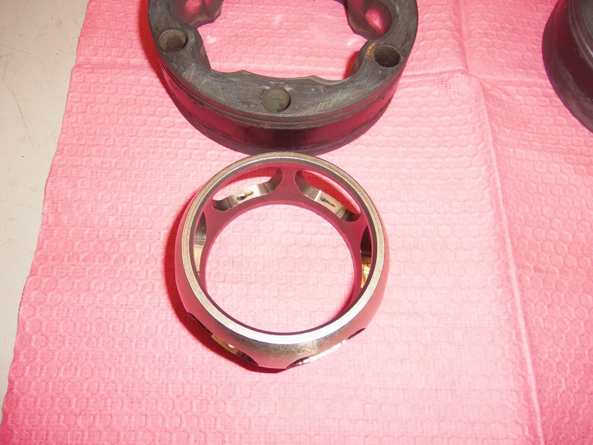
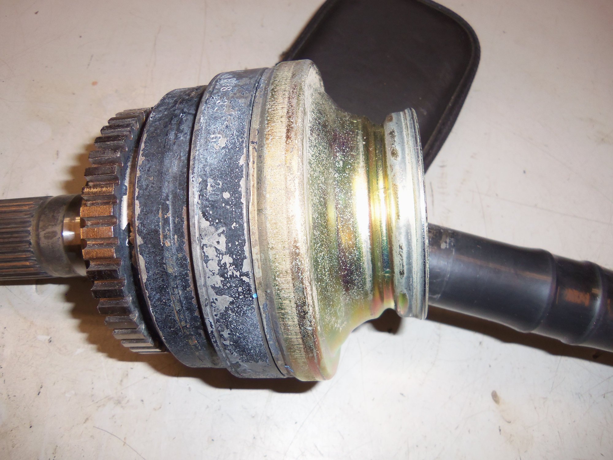
Inside the inner CV joint.
Not too much grease inside the boot.
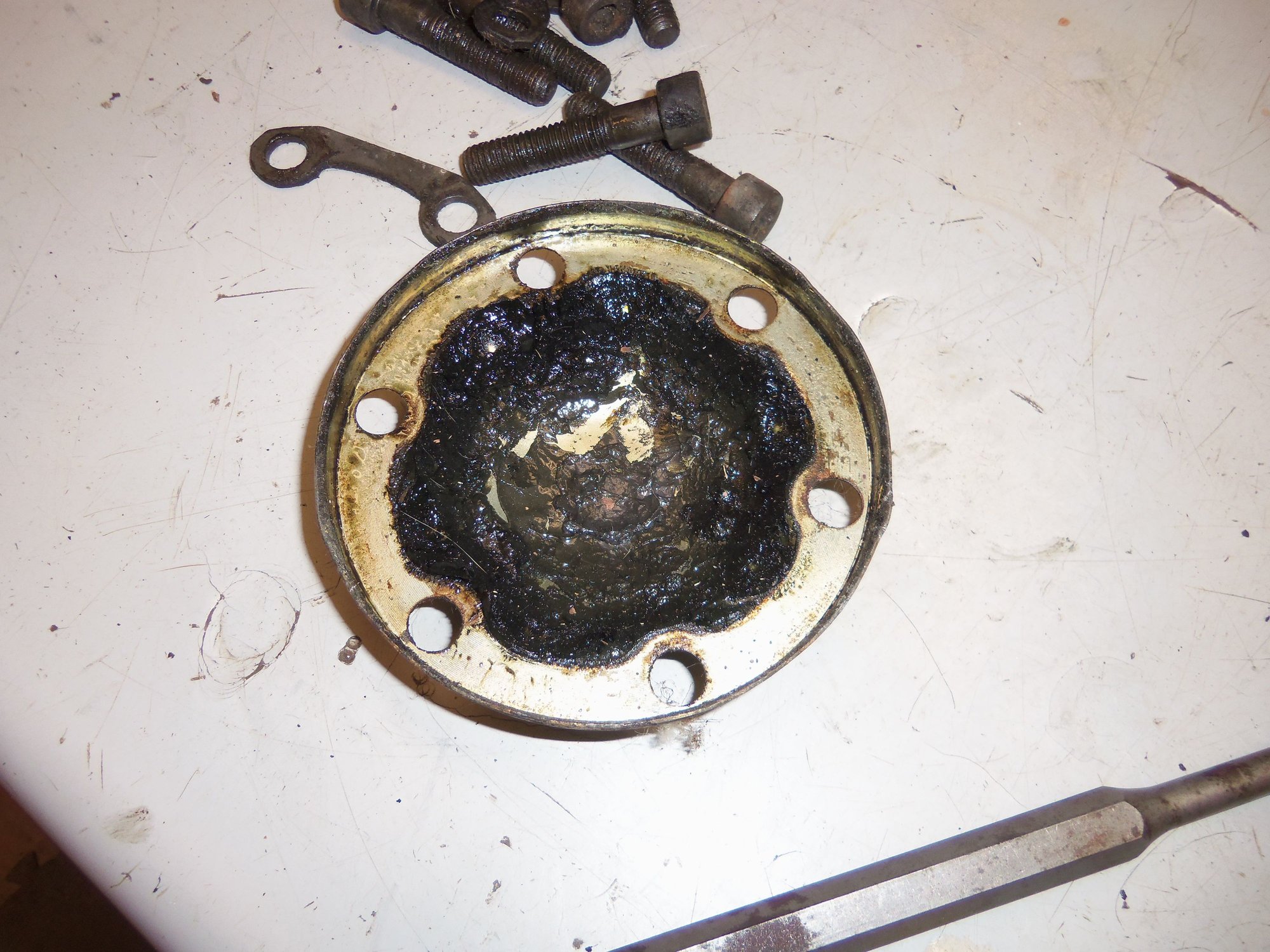
Inside the end cap.
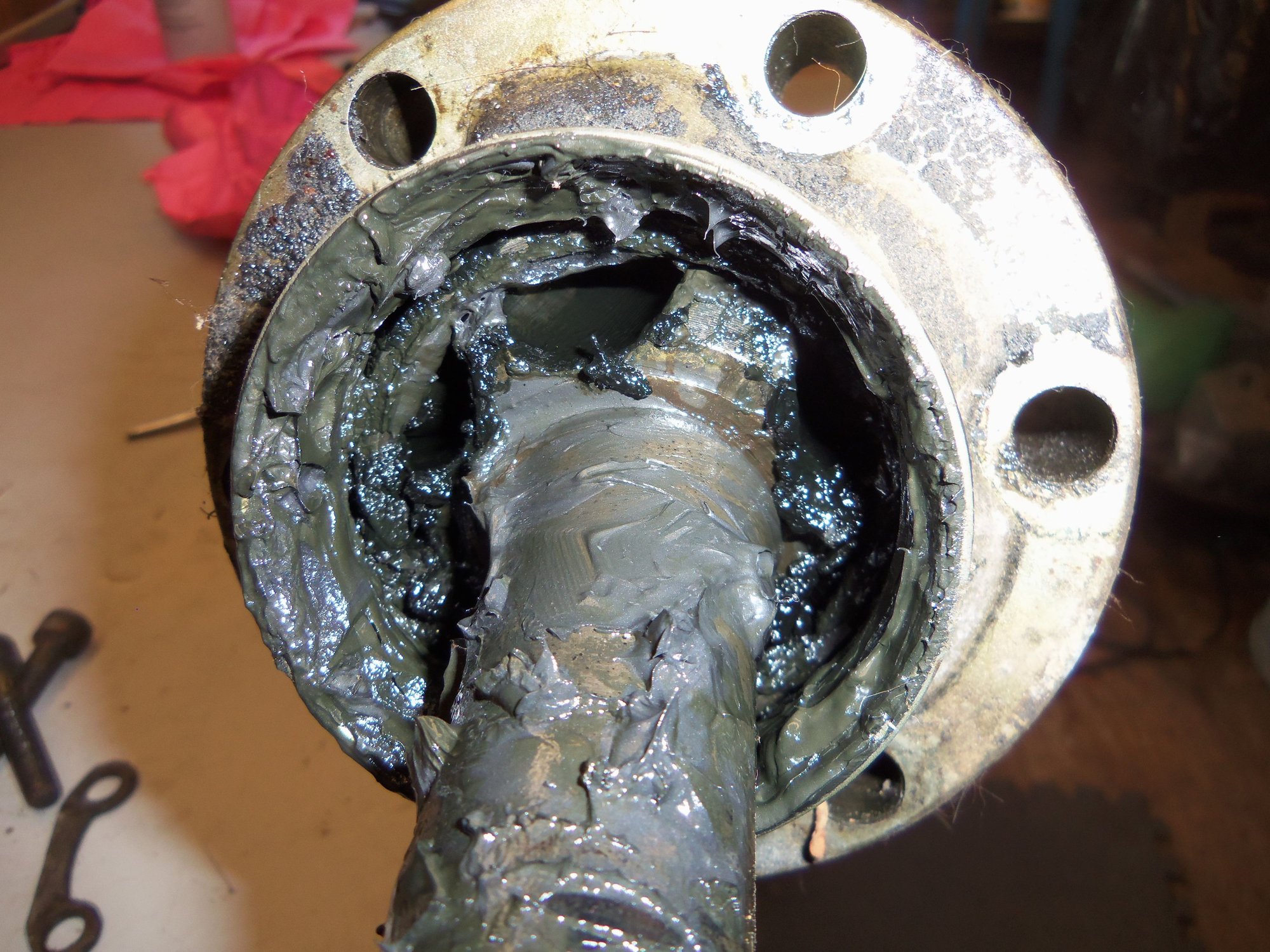
Backside of the CV joint with the end cap removed. Grease is good.
Front side of the CV joint with the inner cap removed. Grease is still good.
I wiped off as much of the old grease from both sides of the CV joint to get a better look at things. I saw no obvious wear or damage. And I saw the original snap rings. The user hostile kind. Luckily, in a rare moment of clarity, I though ahead and bought a proper set of snap ring pliers. The first snap ring came off with no drama. The second went 'SPROING' and is currently somewhere in low earth orbit. I don't do enough snap rings to remember to cover the ring with a rag or such as I take it off.
Its OK, as the new boot kits come with a snap ring.
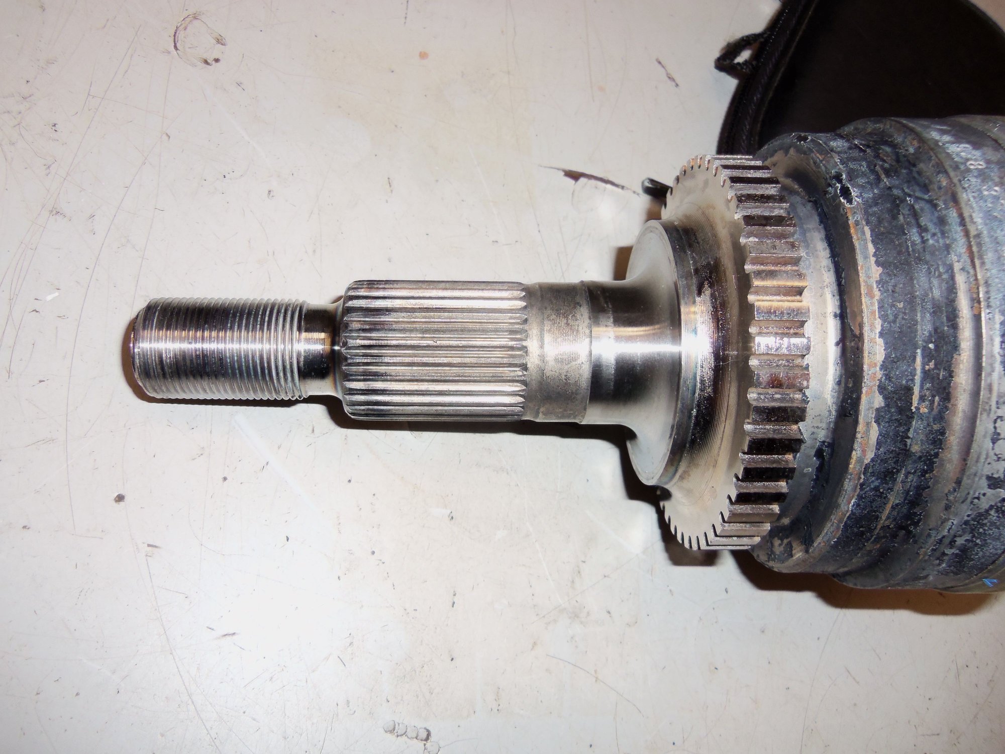
Before removing the inner CV joint from the end of the axleshaft, I wanted to get some good photos. Both Dwayne and the WSM mentioned certain characteristics for alignment. So, I wanted to document them. And be able to properly reassemble the CV joints.
Snap ring at the end of the shaft.
Old school snap ring. No ears that us whipper snappers are used to. This snap ring is on the bench, as opposed to the other one. Which is somewhere in low earth orbit.
Note the end of the hub at the end of the shaft is smooth.
Note the hub has a raised boss at the end against the shoulder on the axleshaft.
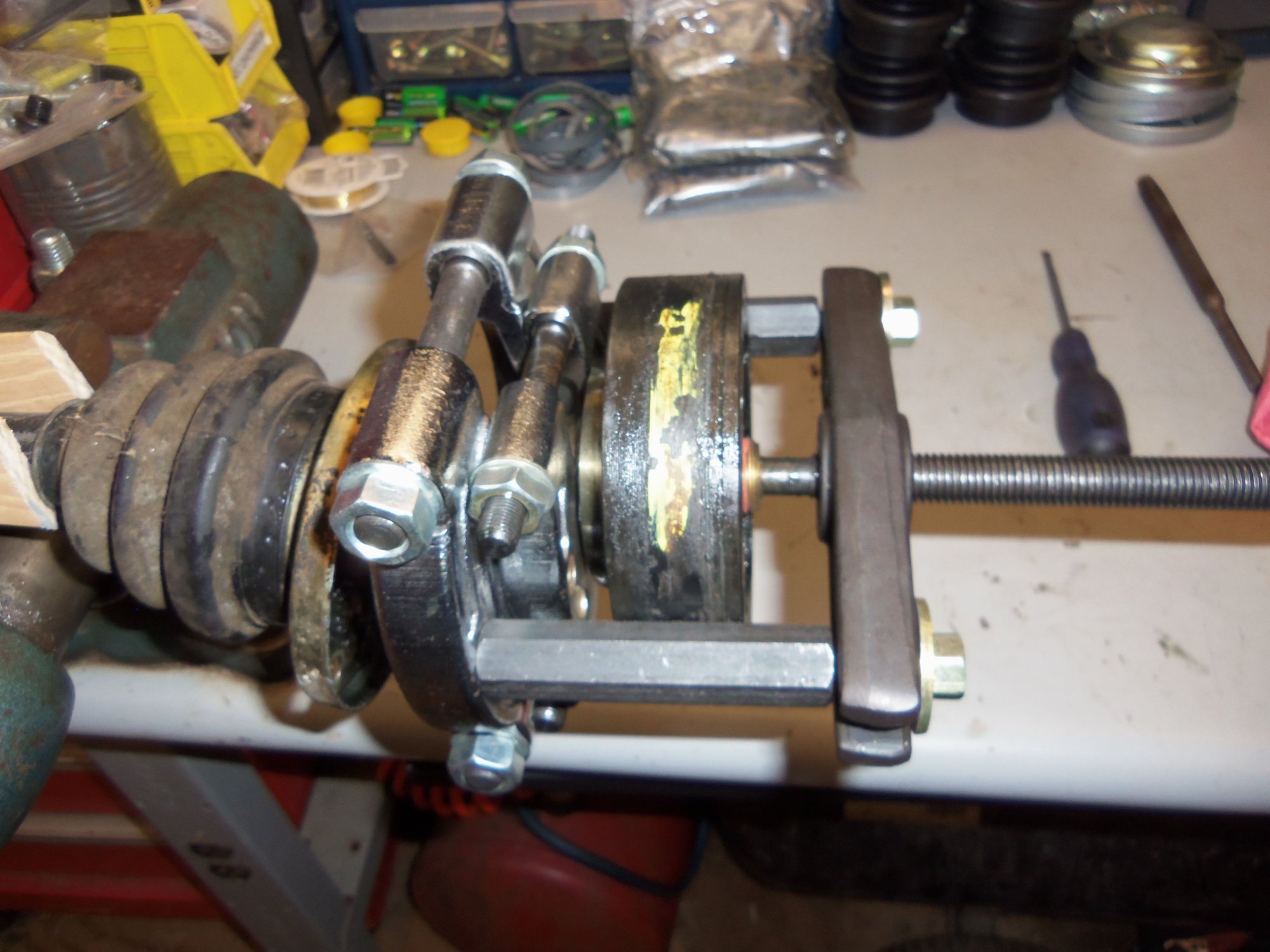
Because I am...hard headed(read STUPID), I ignored the part in Dwayne's write up and in the WSM where the axleshafts had to be pressed out of the inner CV joints. That doesn't apply to me. I'll be fine in my workshop! I rigged up a puller with two layers of bearing separators. Not sketchy in any way shape or form. In my defense, I only wanted to apply pressure to the hub and not to the body and *****.
Needless to say, it didn't work. The CV joint hub did NOT budge. Realizing I was wrong and they were right, I loosely reassembled the caps and boot on the inner CV joint, then bagged it up.
I did all the above steps to the other axle, with none of the mistakes. That one was also bagged up.
Clown rig of a puller with two bearing separators.
Puller bearing down on the axleshaft via protective brass pipe plug.
Outer bearing separator pulls on inner bearing separator which pulls on inner edge of CV joint hub. Nothing moved.
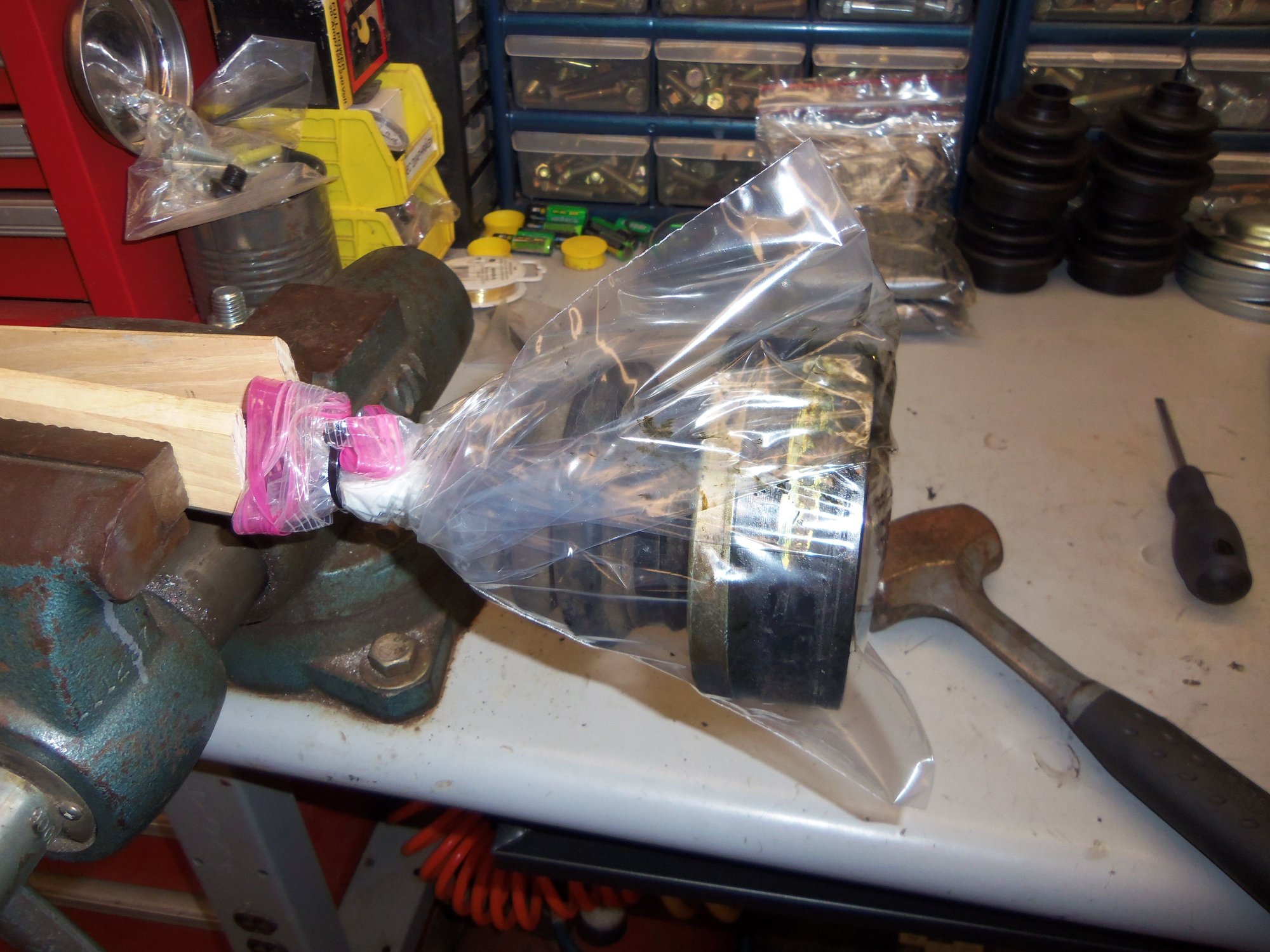
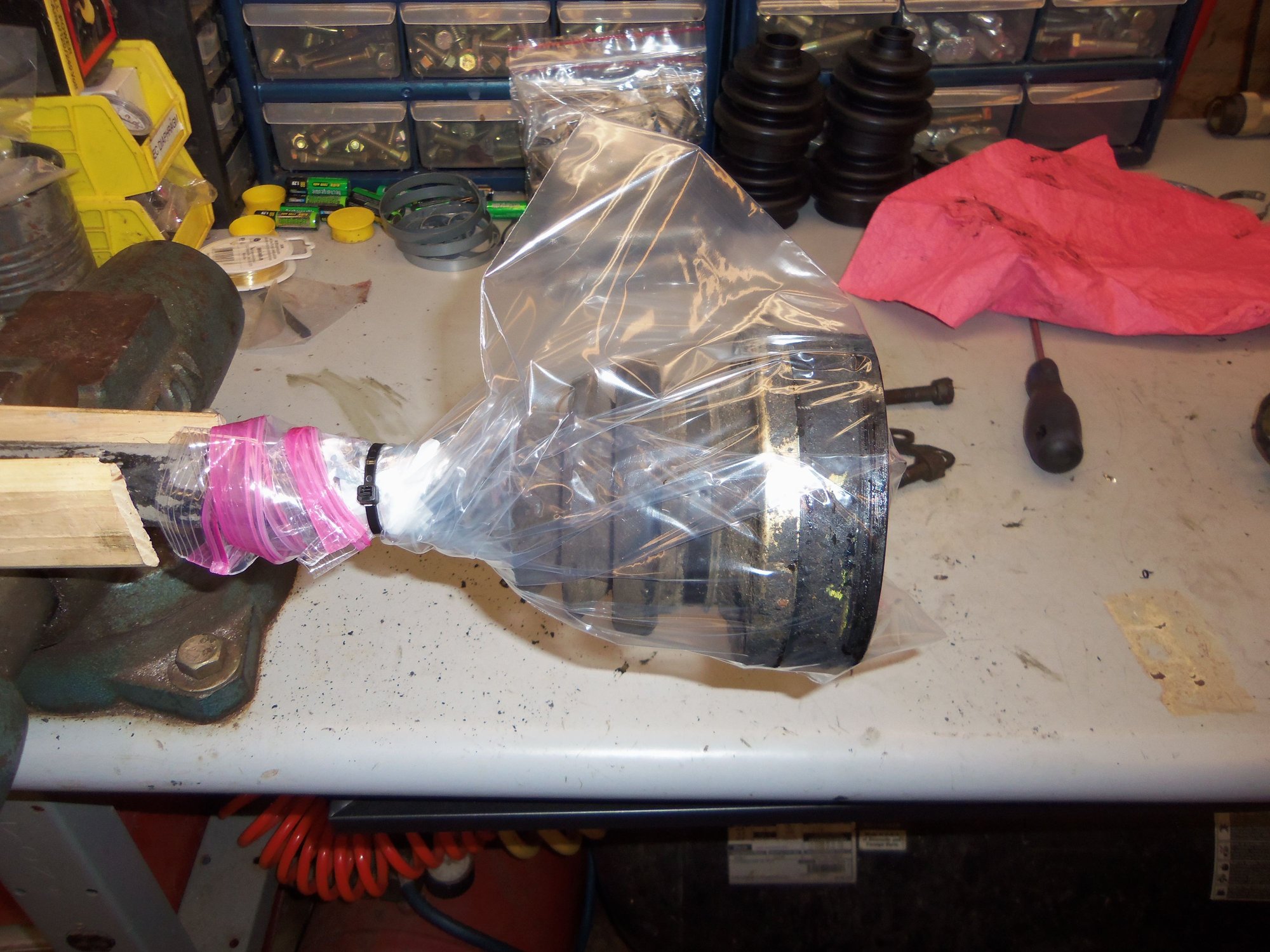
Driver's side inner CV joint bagged for transport.
Passenger's side inner CV joint bagged for transport.
They both took a trip to my mechanic's shop. I wanted to use his large press. My little 12-ton press could have easily pressed the shafts out. However, the opening in the bed was not big enough to fit the outer CV joint through.
Glenn's 20-ton air over hydraulic press and a large bearing separator made short work of both inner CV joints. Then back to my shop.
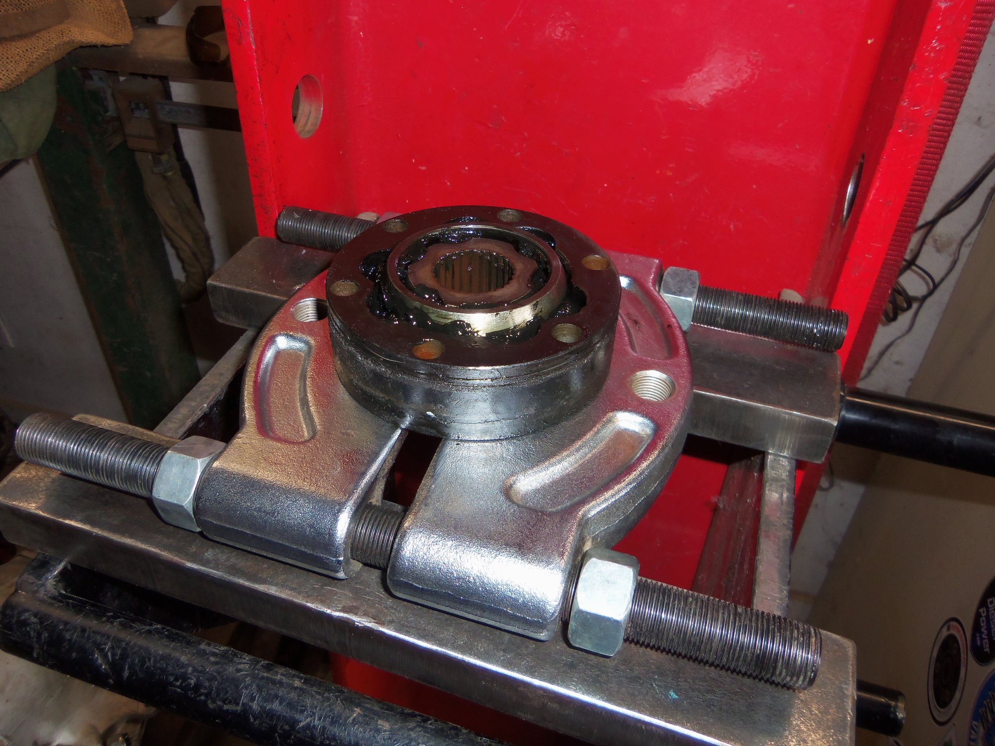
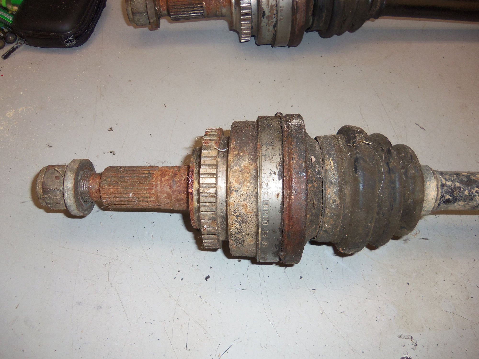
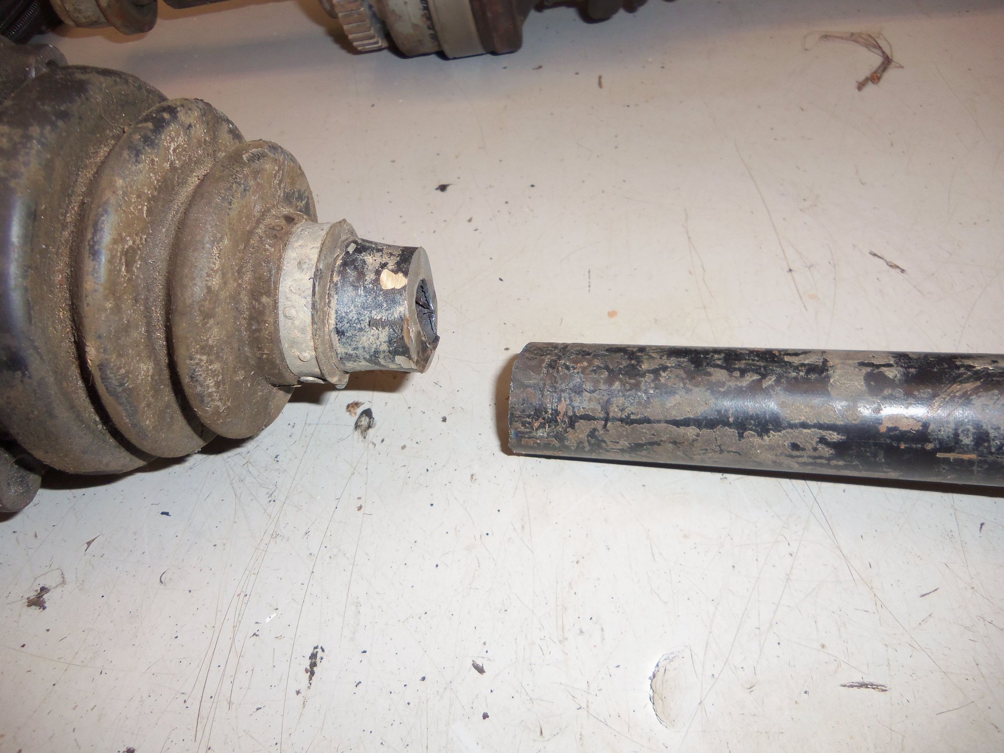
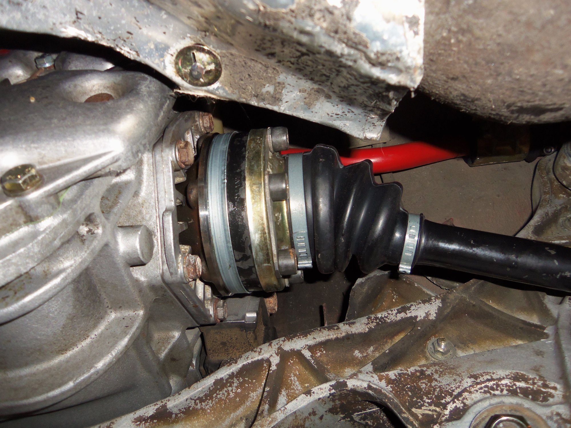
Passenger's side inner CV joint. Note the lack of axleshaft.
Here it is! This one came free quicker than I expected when pressing. As a result, it landed. Note the wooden landing board Glenn has at the base of his press. Not the first thing to have fallen here...
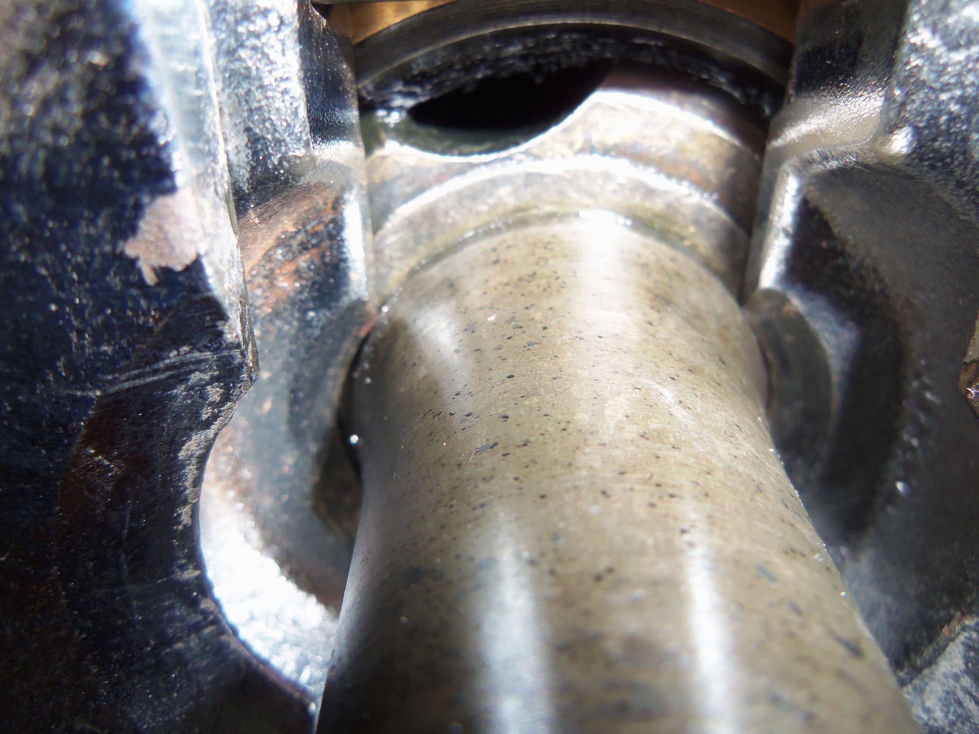
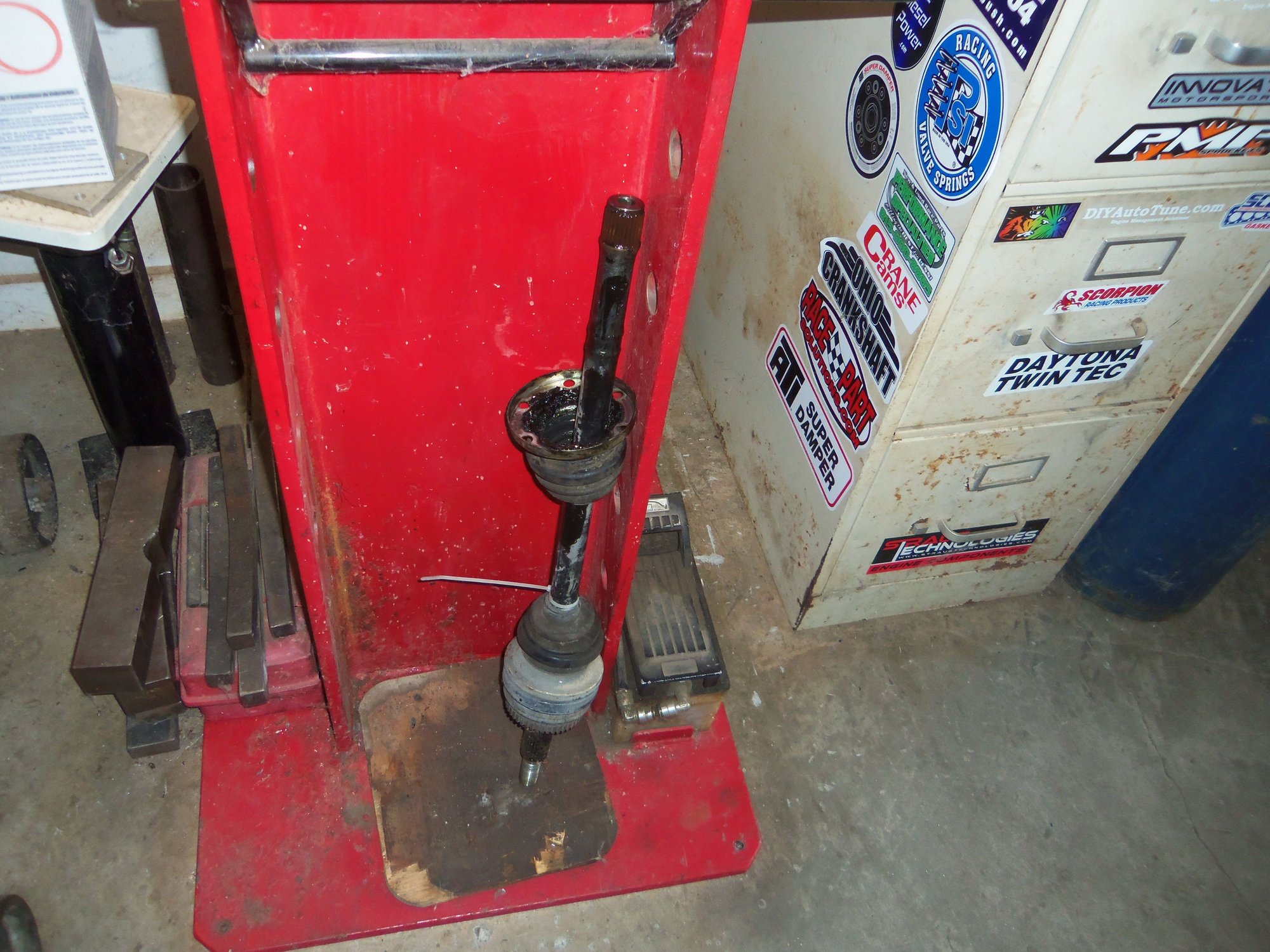
Pressing axleshaft out of driver's side inner CV joint. Bonus points to whomever can tell me what kind of automatic transmission is sitting next to the press...
Close up of spacer to push out axleshaft.
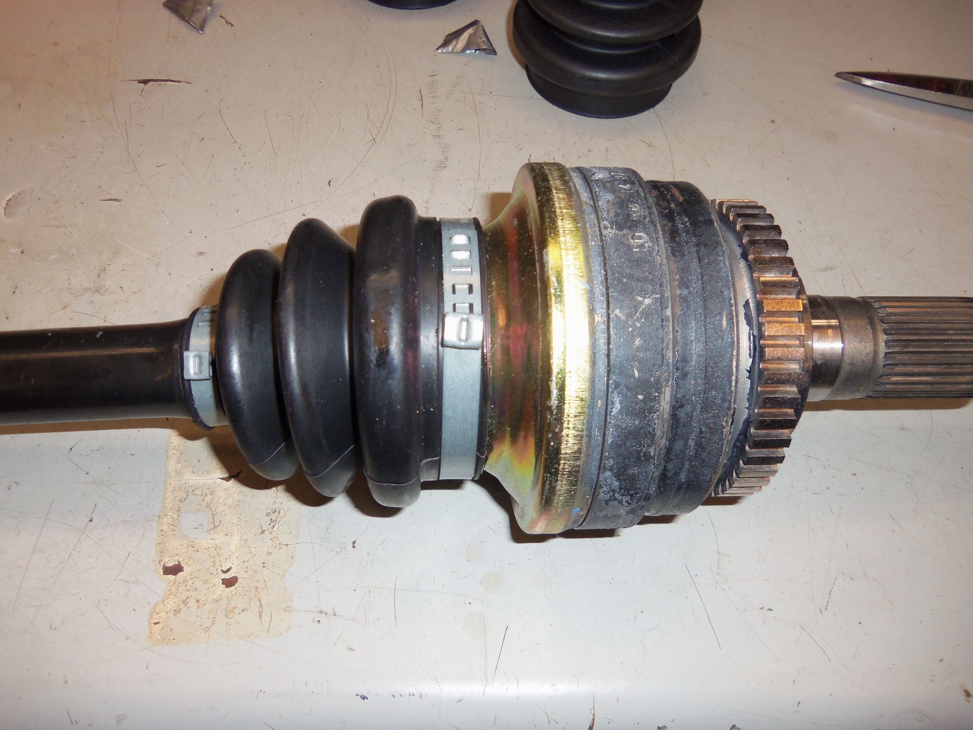
Driver's side inner CV joint.
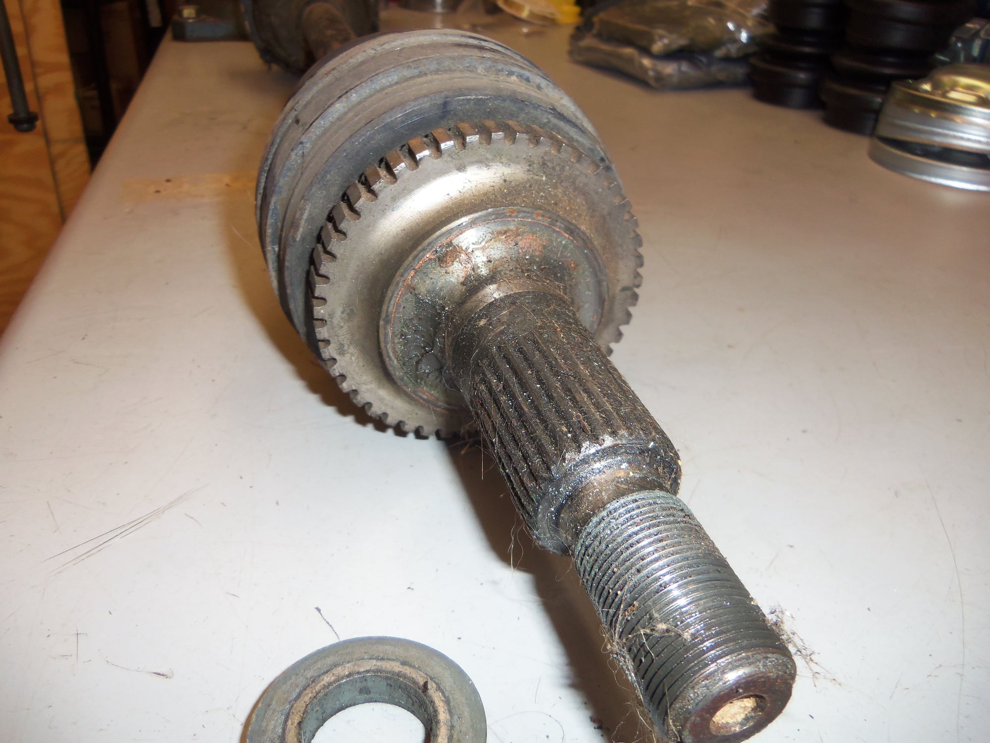
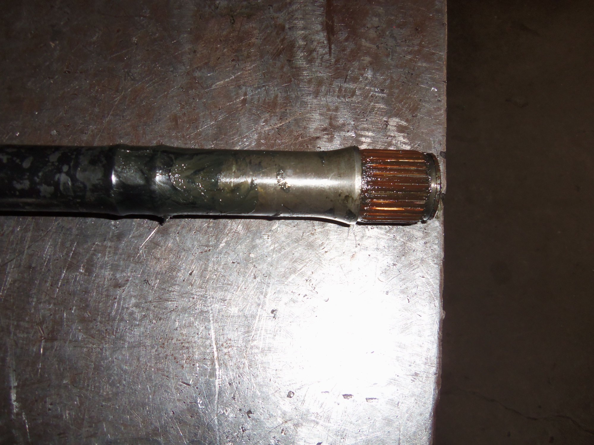
Splined end of driver's side CV axle.
Before disassembling each CV joint, I took more photos documenting alignment characteristics.
Then everything got thoroughly wiped down with rags to remove most of the grease. I have a nifty parts washer. However, I don't want to contaminate the solvent if at all possible. So, any and all grease/crud/dead chickens/etc...get wiped off before anything goes into the solvent tank.
Smooth surface of the hub facing the end of the axleshaft.
Machined rings in the CV joint body at the same end as the smooth end of the hub and the end of the axleshaft.
Raised boss on the surface of the hub facing the shoulder on the axleshaft.
No machined rings in the CV joint body at the same end as the raised boss end of the hub and shoulder on the axleshaft.
And...all parts went for a bath in the parts washer. One joint at a time, so as not to mix anything up.
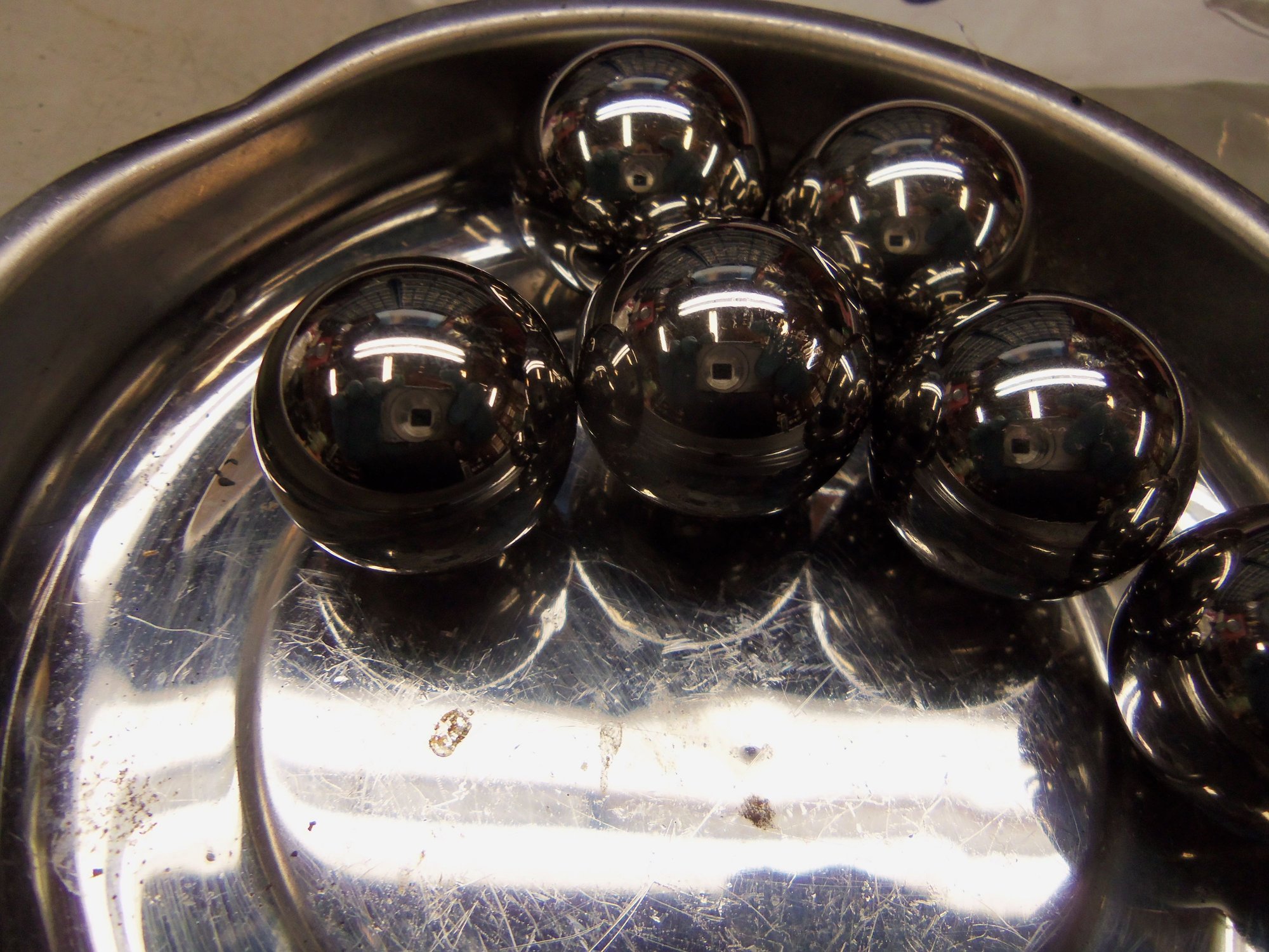
The clean parts were given a thorough inspection. I was pleased to see what I thought was minor wear in the hubs, cages, and bodies. No wear at all was seen on the *****.
Driver's side inner CV joint, in from the parts washer. Note the required Mtn. Dew can at the top left of the photo...
Passenger's side inner CV joint, in from the parts washer.
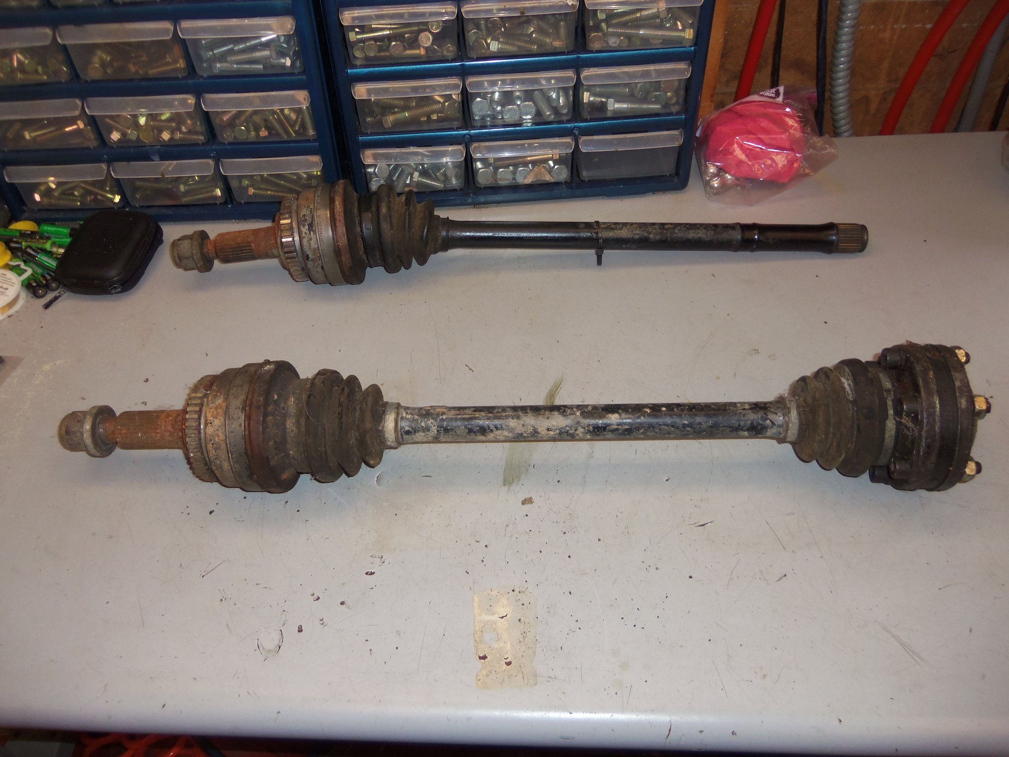
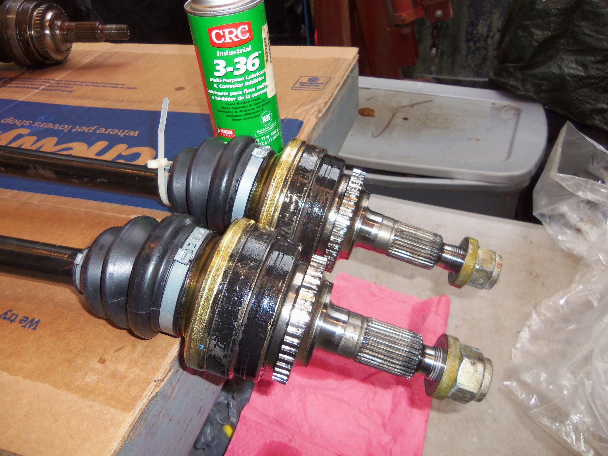
Driver's side inner CV joint parts on the left, passenger's side on the right.
NOTE: the rest of these photos are of the driver's side inner CV joint parts, but are representative of the passenger's side inner CV joint parts as well.
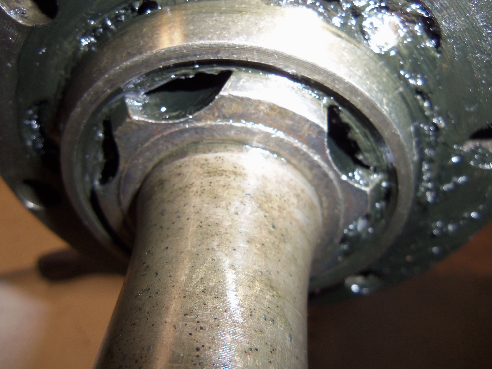
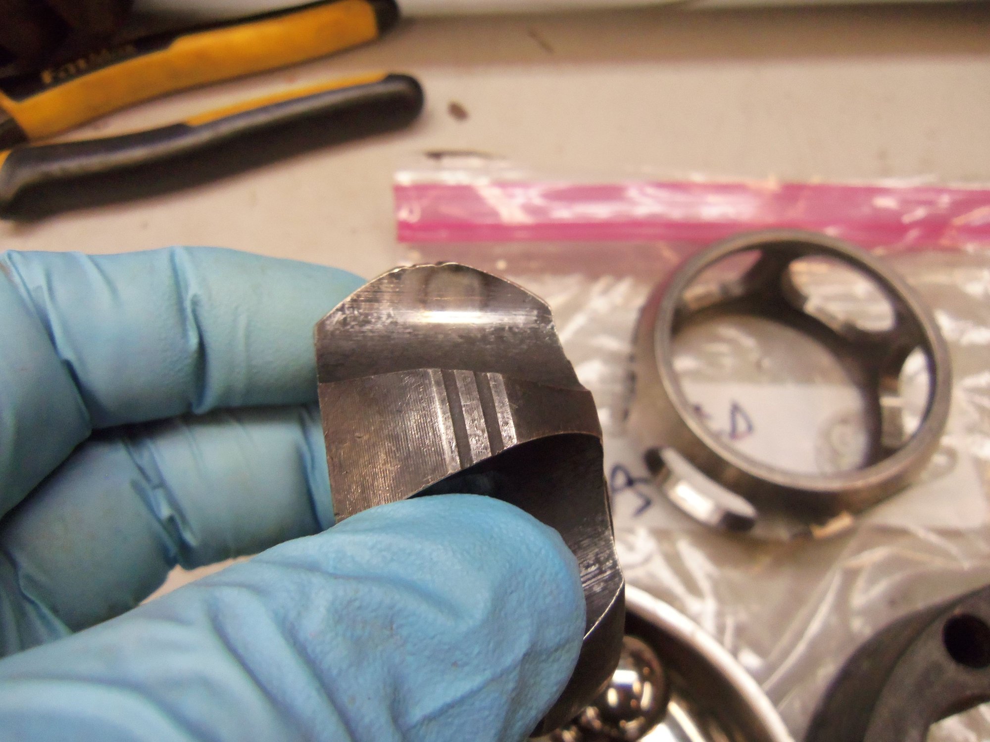
Note the undercut splines at the end of the hub that goes against the shoulder on the axleshaft. This is why the snap ring will not go on if the hub is backwards. The undercut part of the splines goes over the edge of the shoulder on the axleshaft. Swap it around and the axleshaft won't go far enough through the hub for access to the snap ring groove.
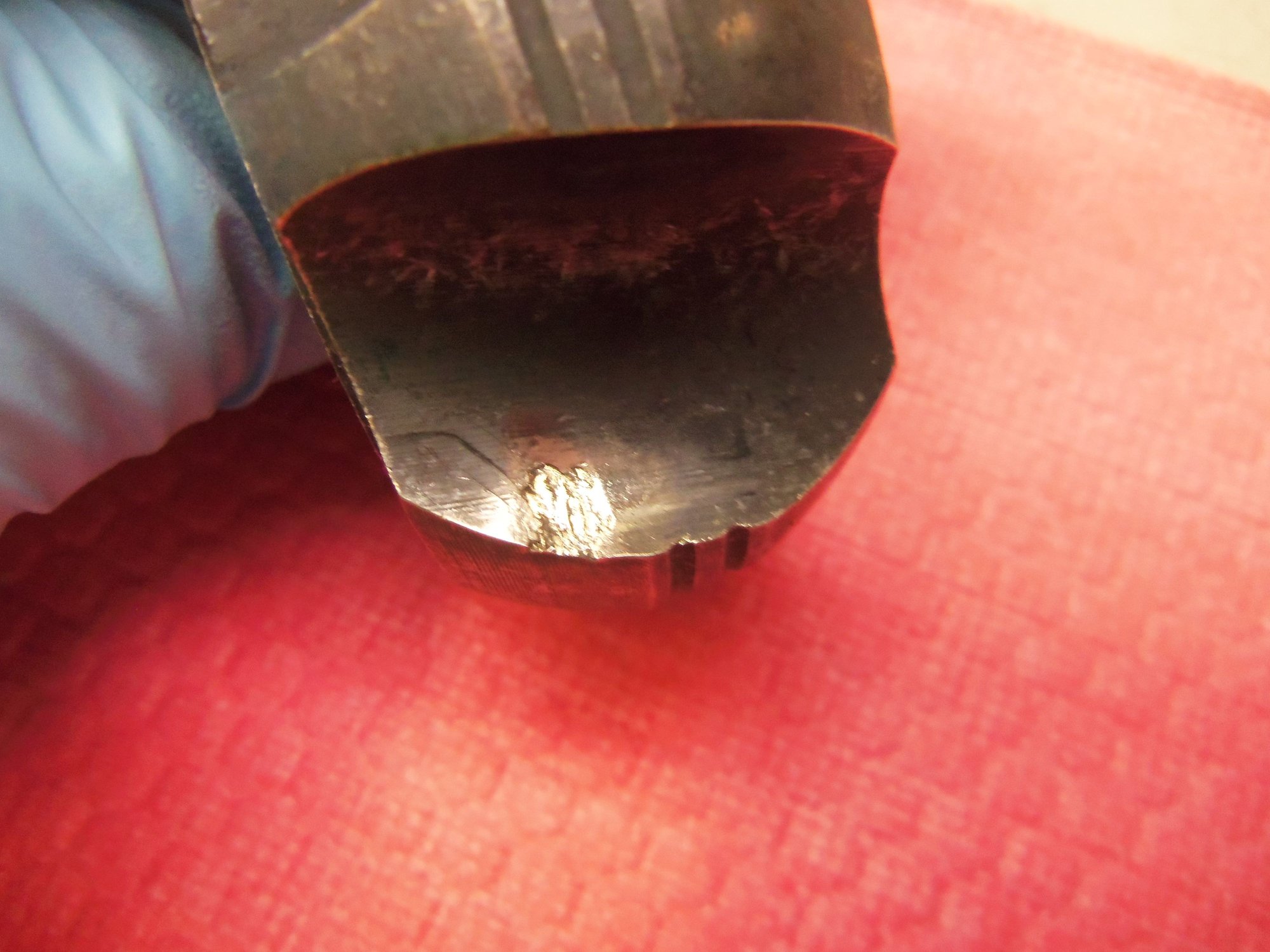
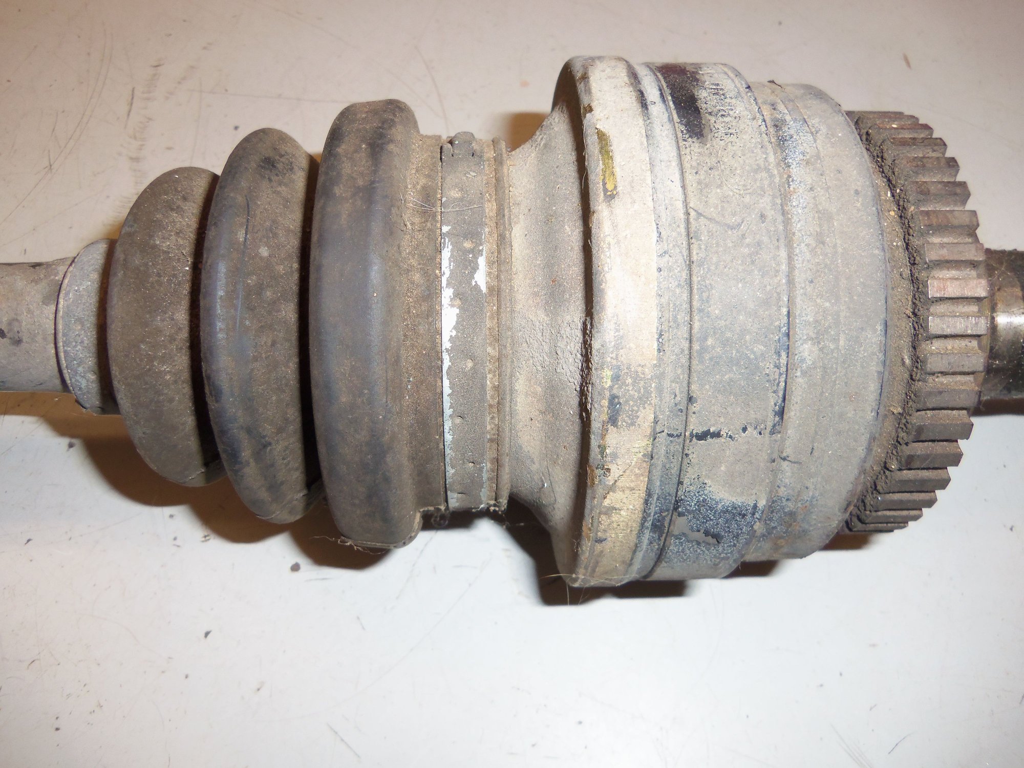
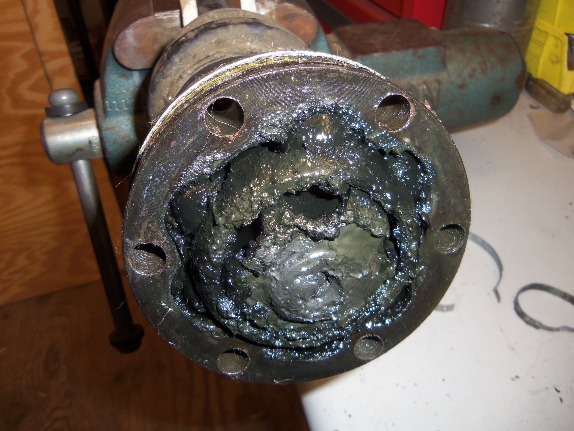
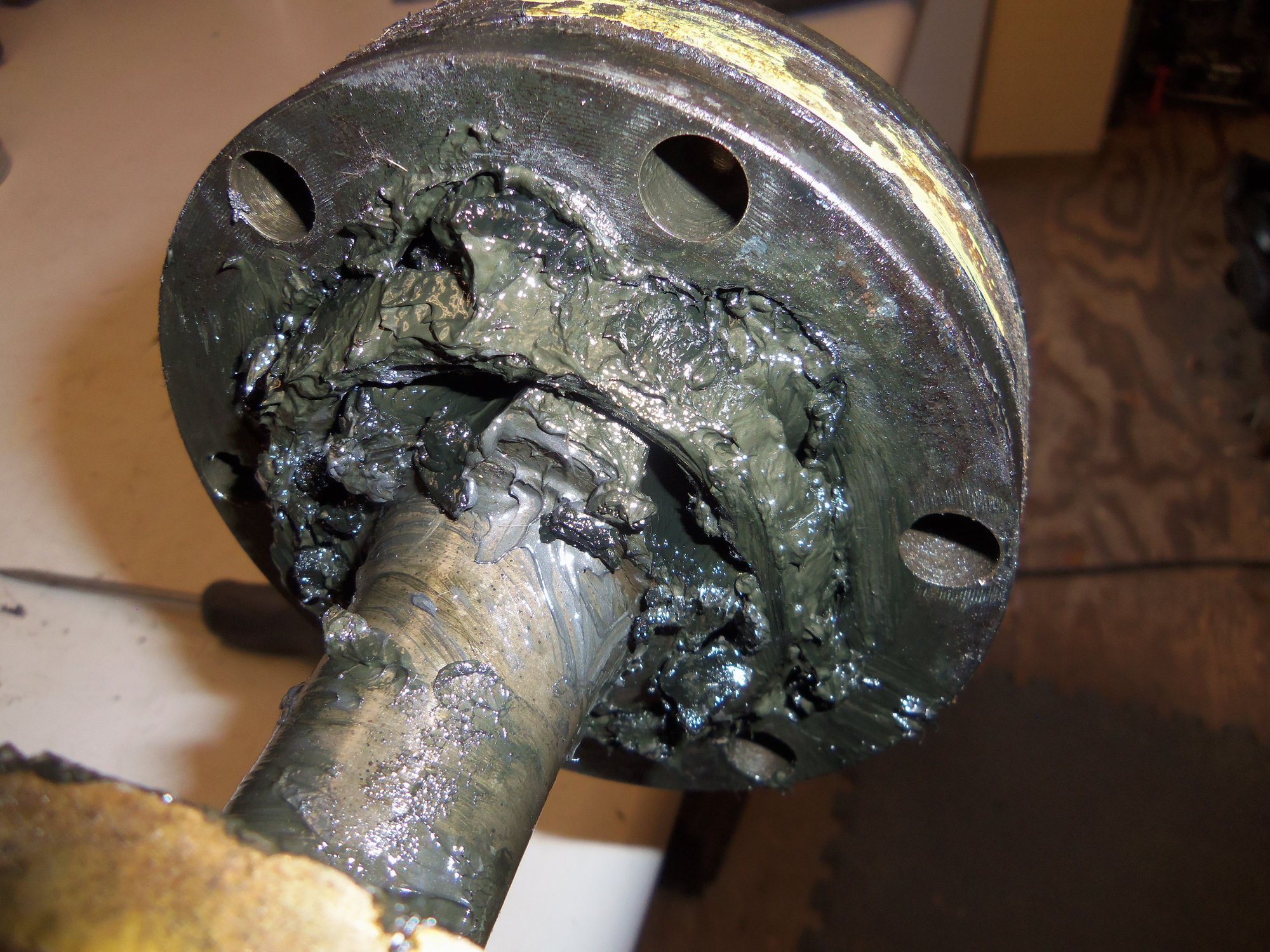
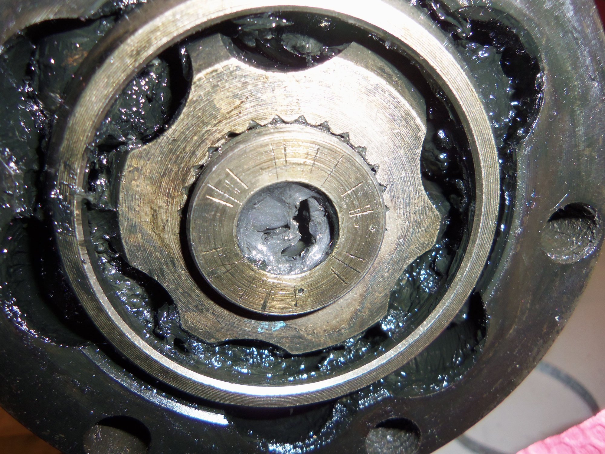
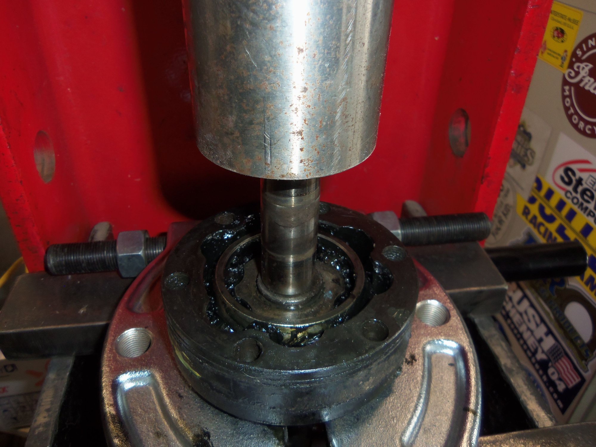
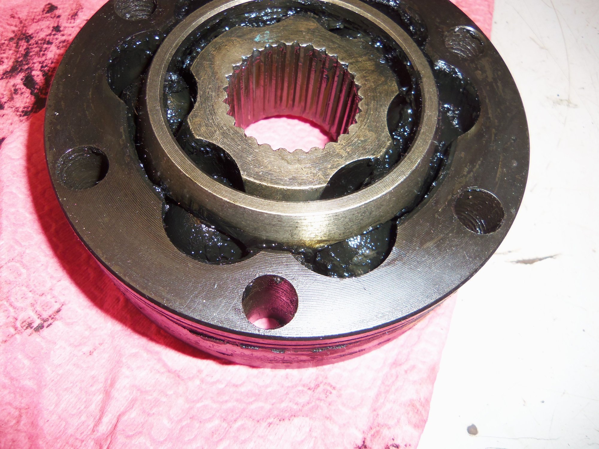
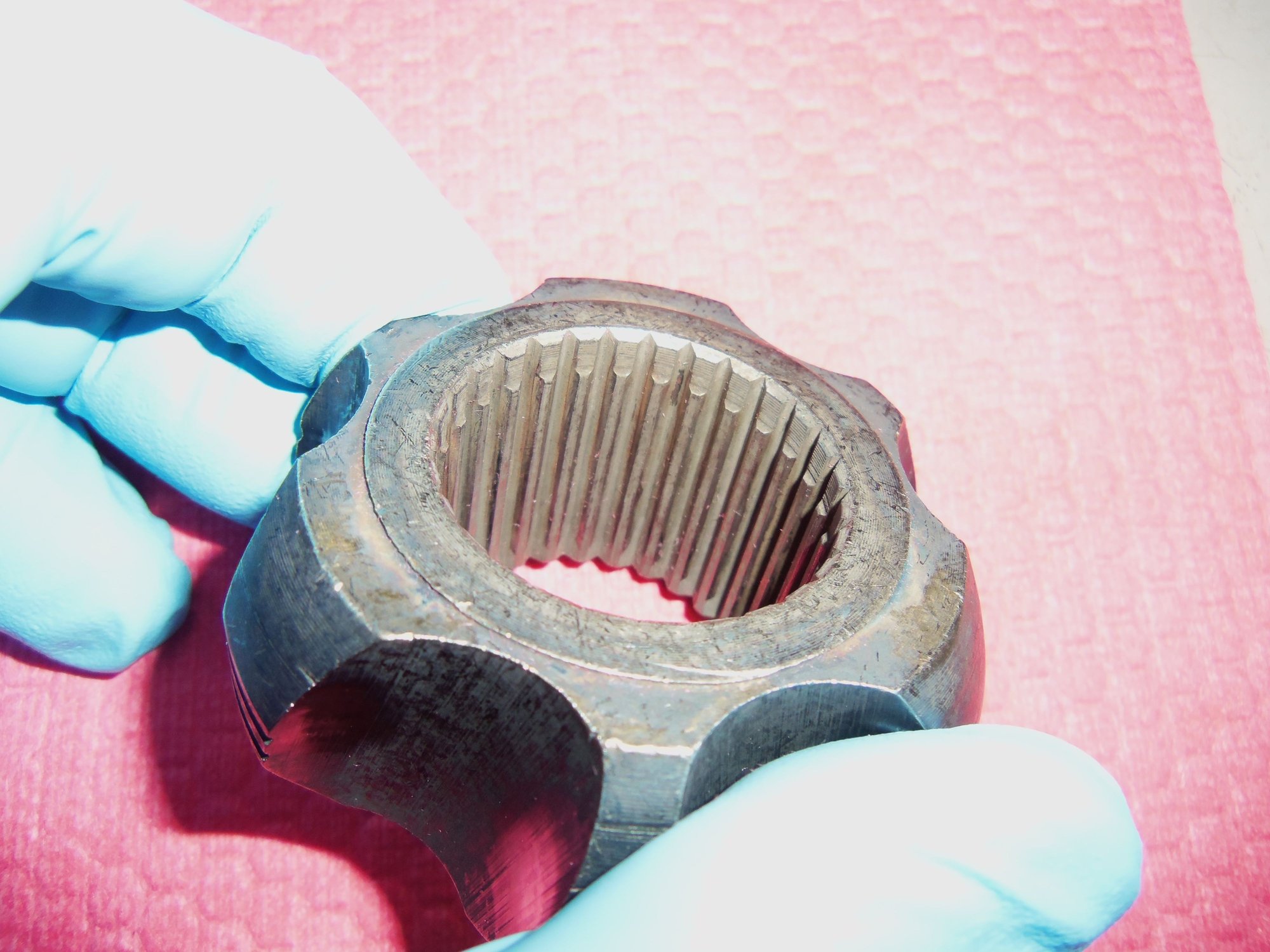
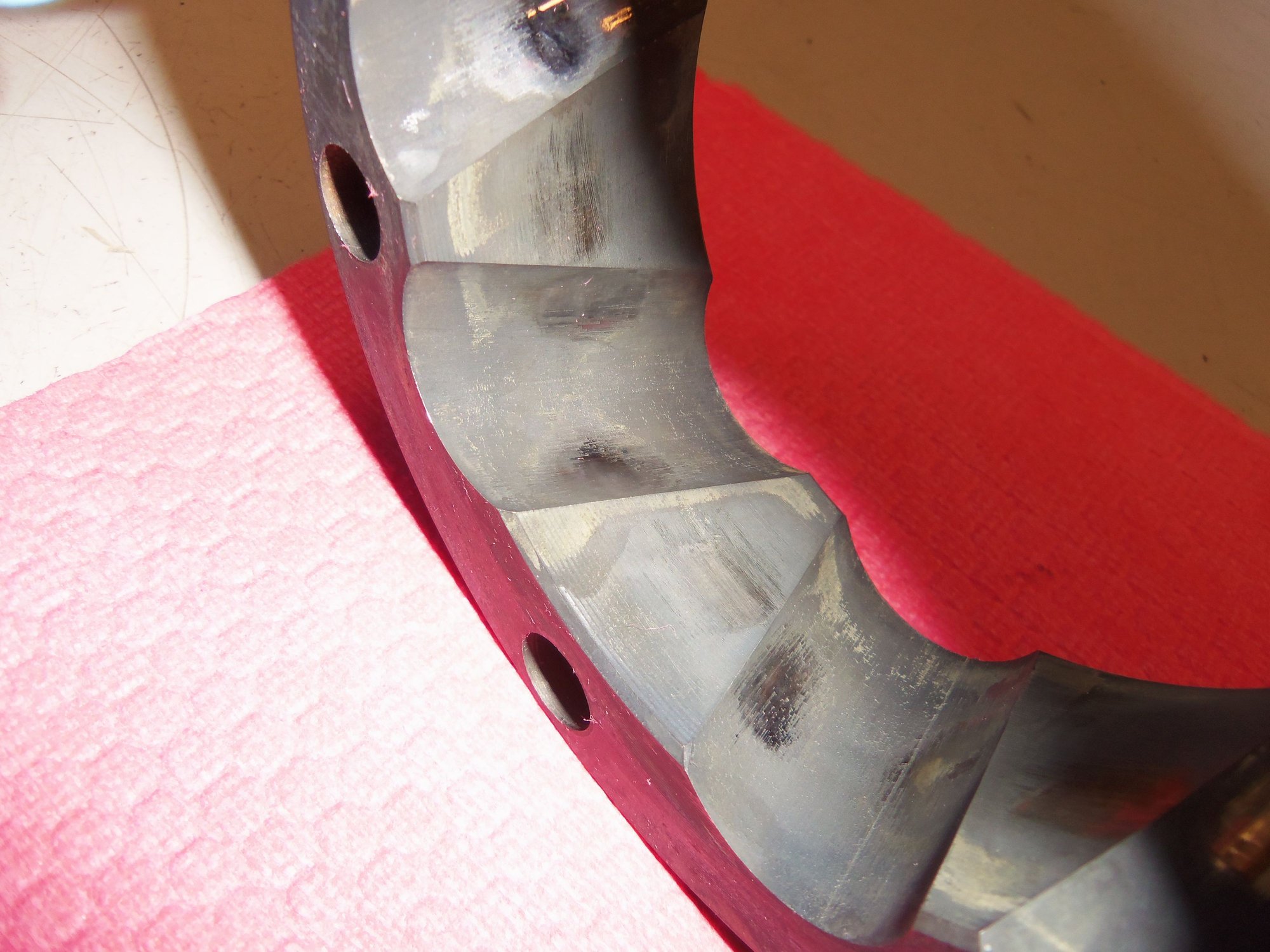
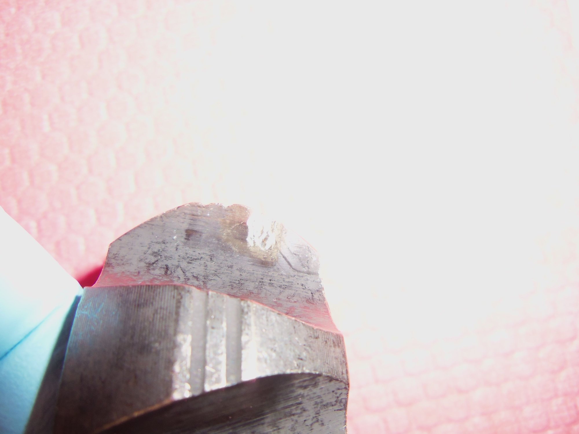
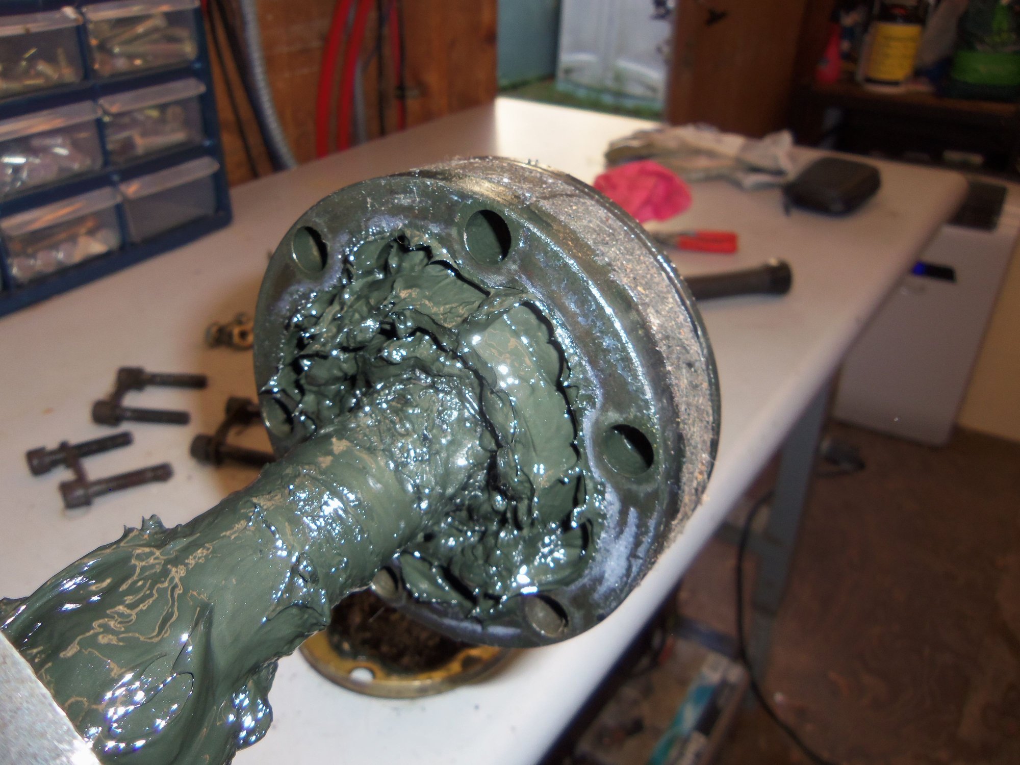
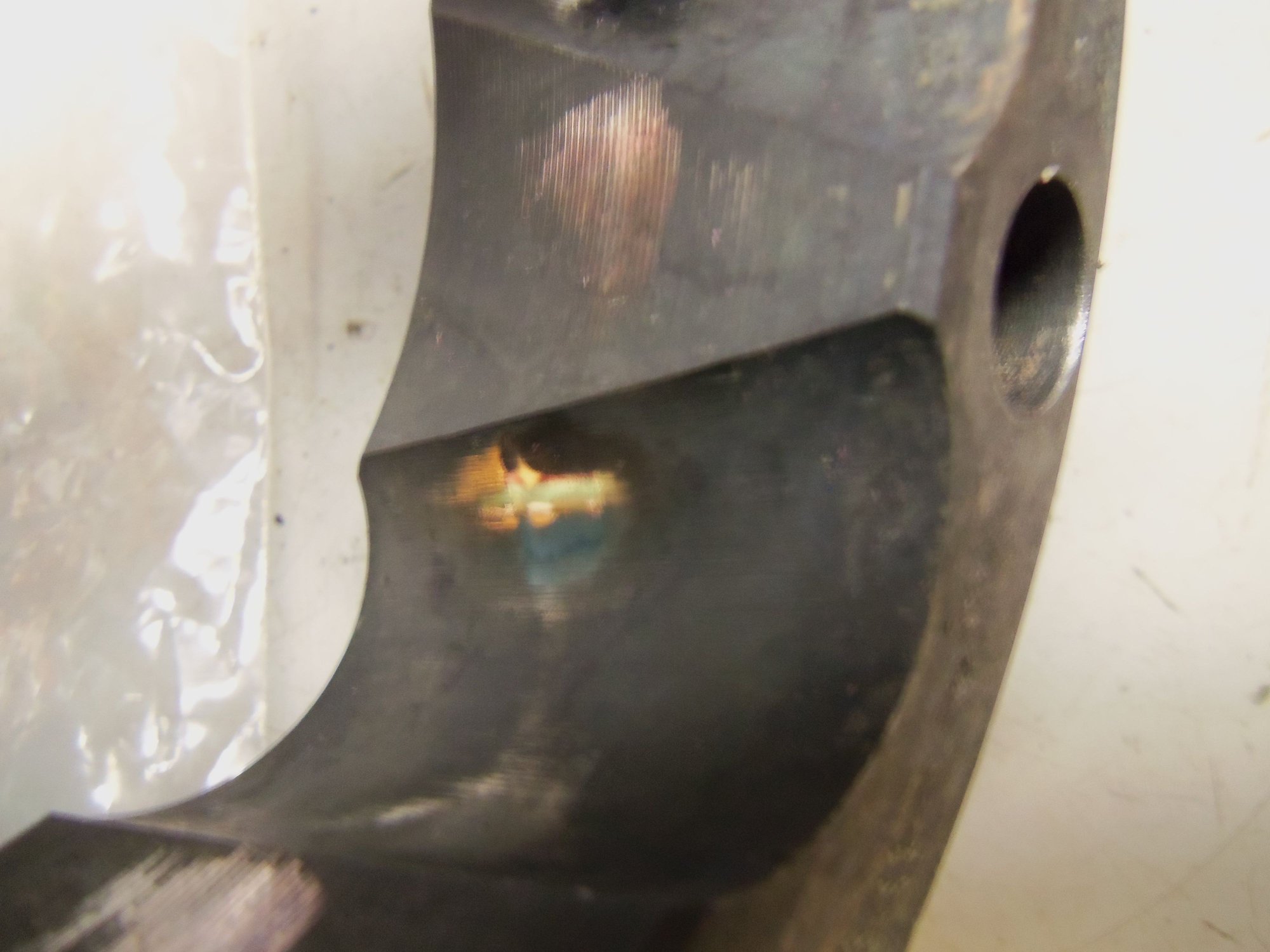
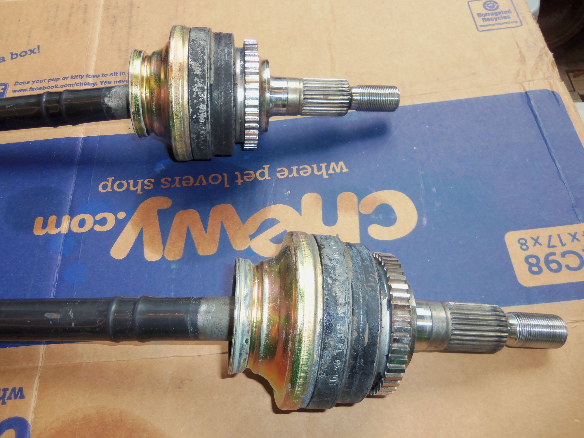
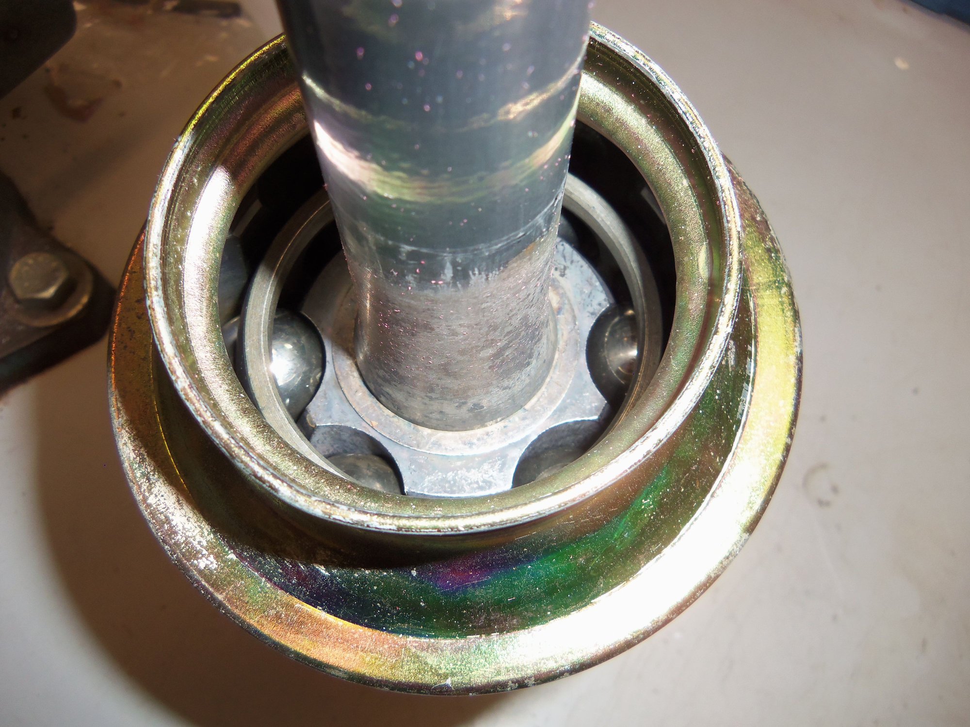
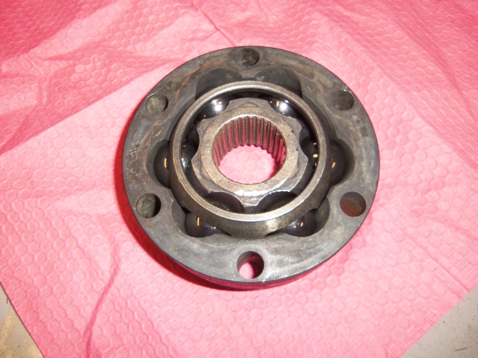
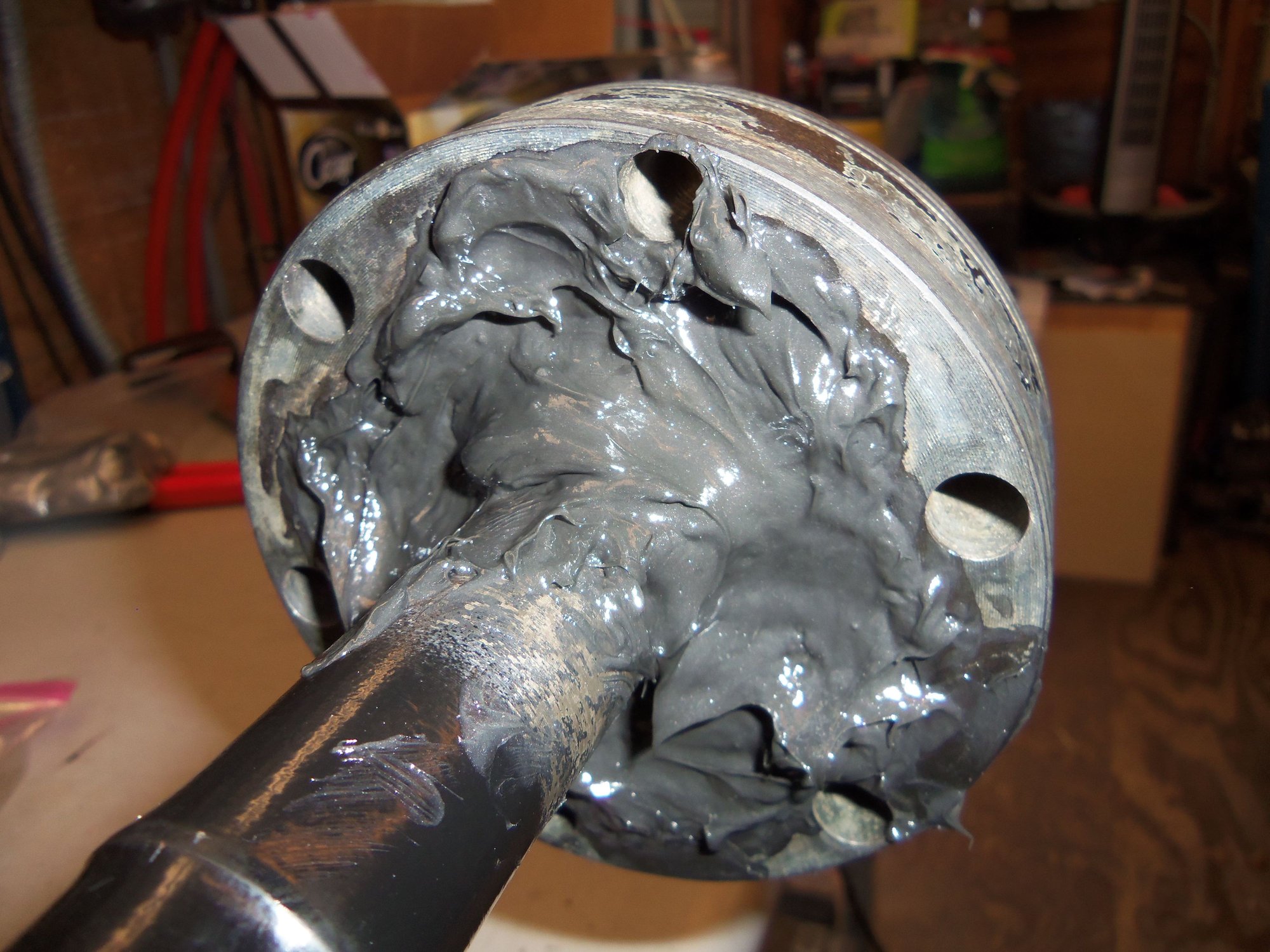
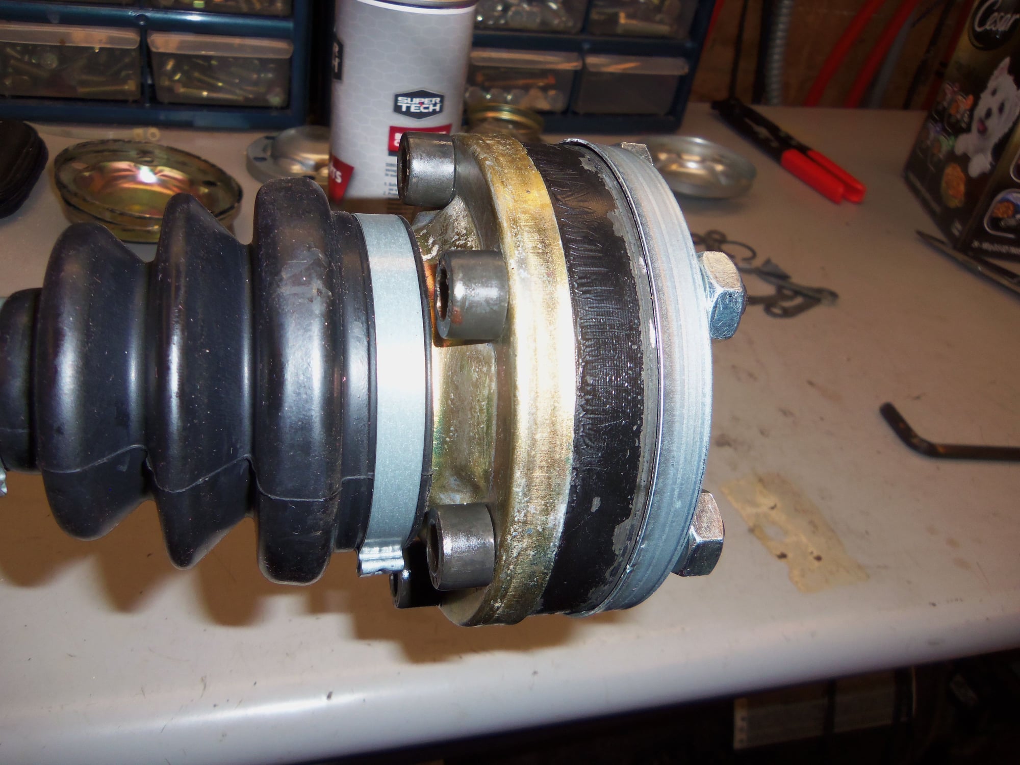
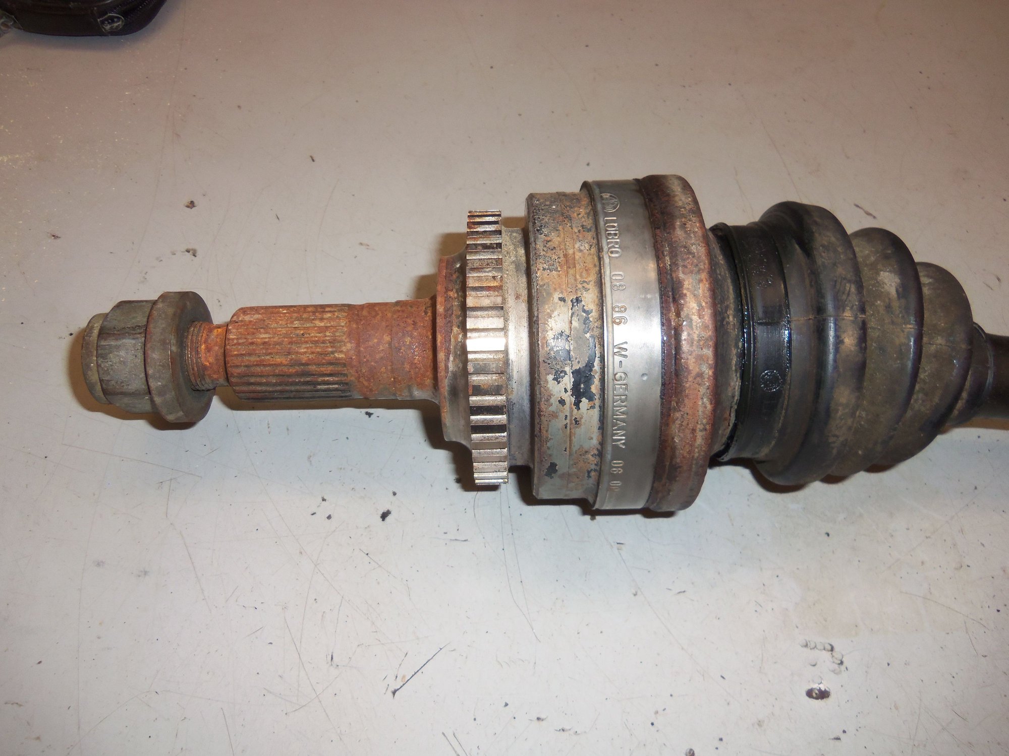
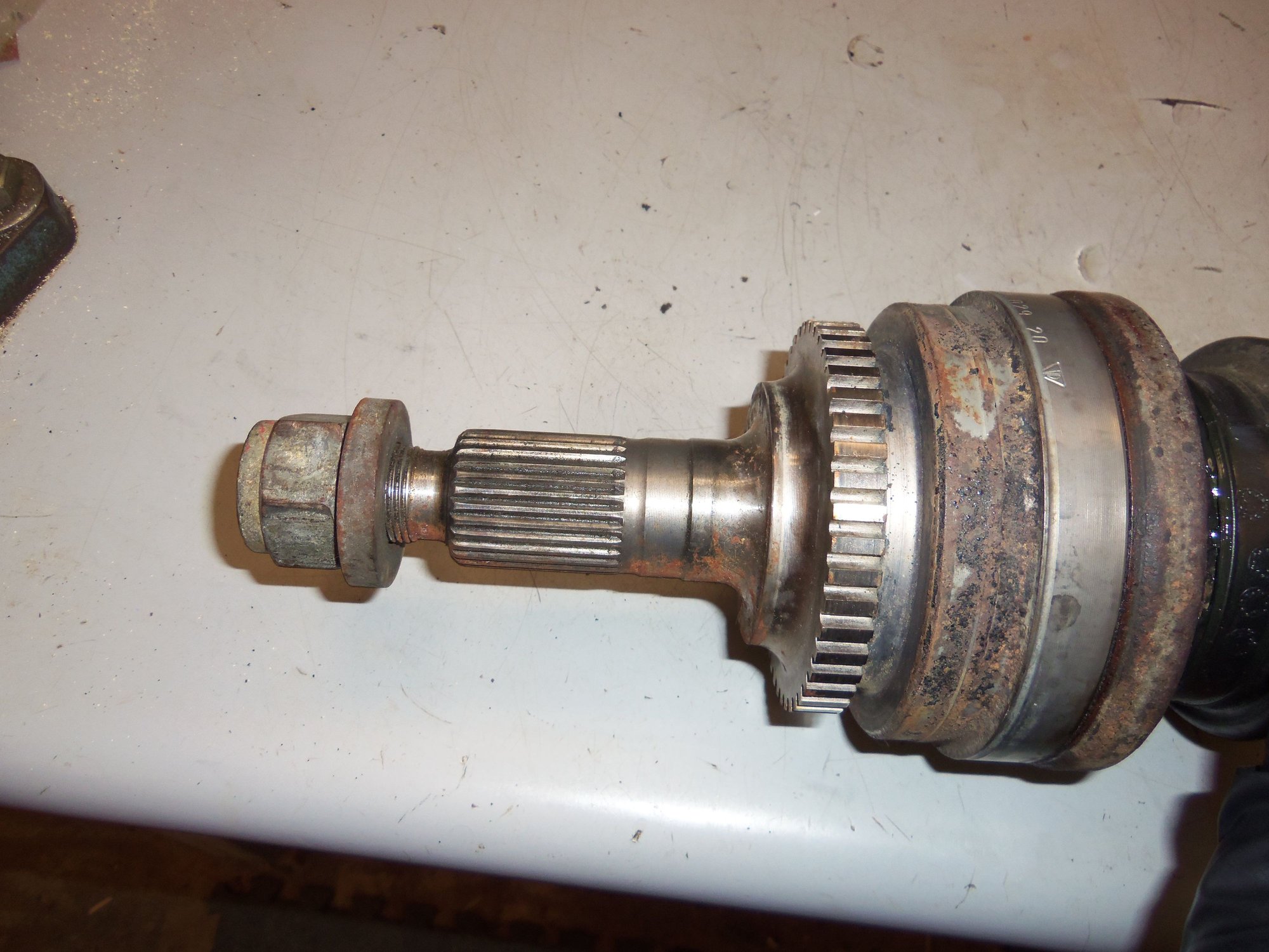
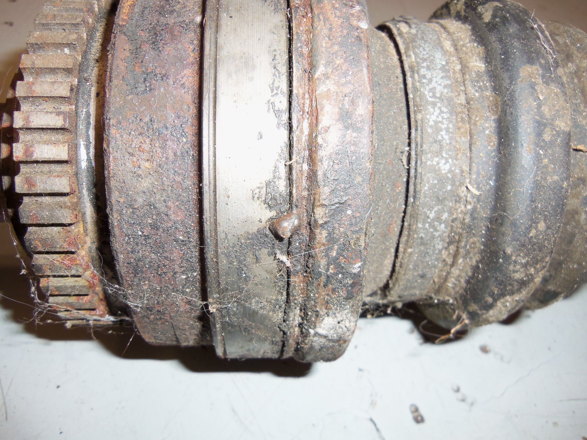
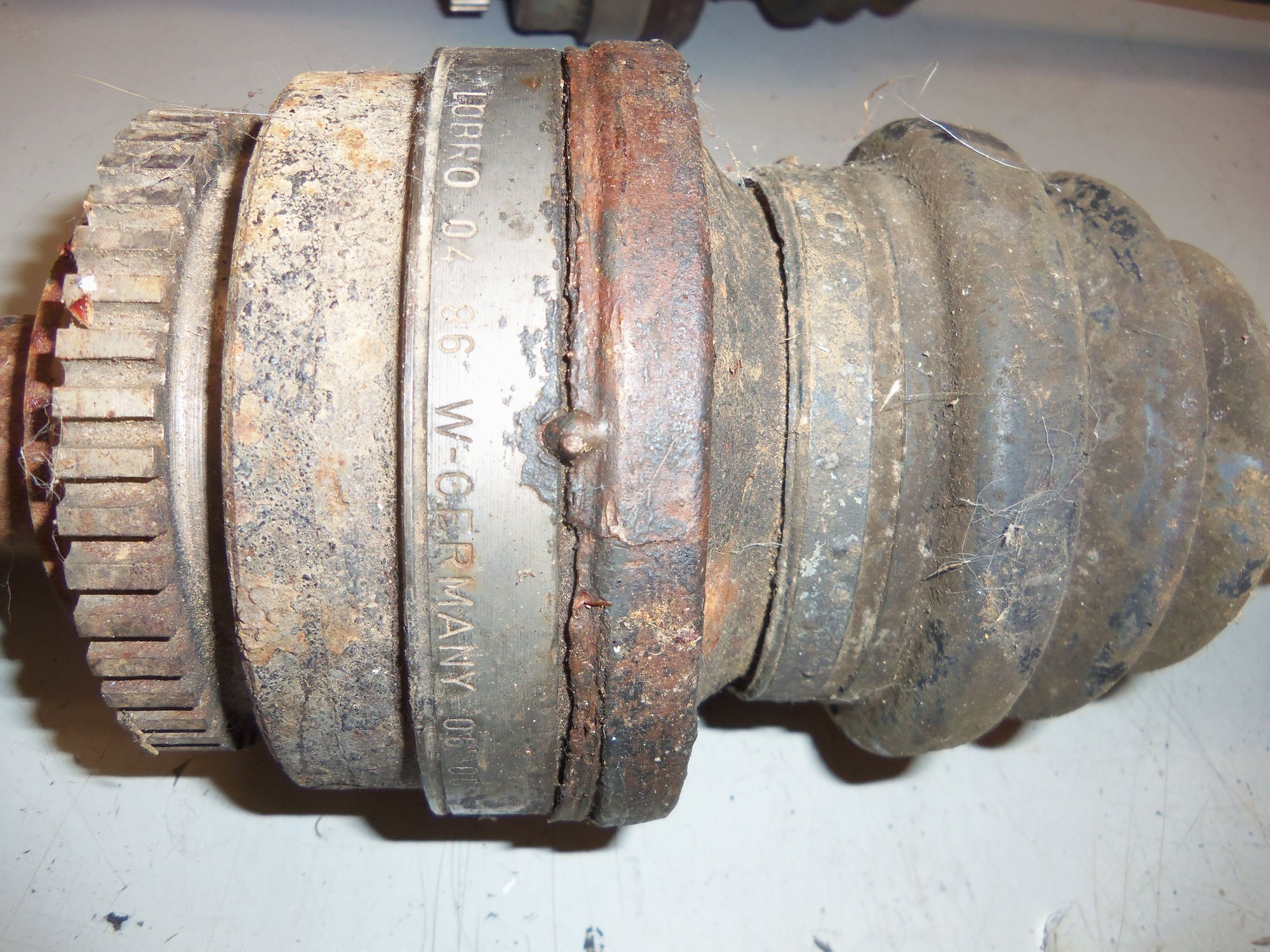
Then I looked closer at the passenger's side inner CV joint hub.
Near the end of one of the ball slots, at the end of the wear path of the ball, was a shiny pit. It looked like a casting defect. It was not raised above the surface. However, it was shiny and obvious that the ball was riding over it.
Dammit...
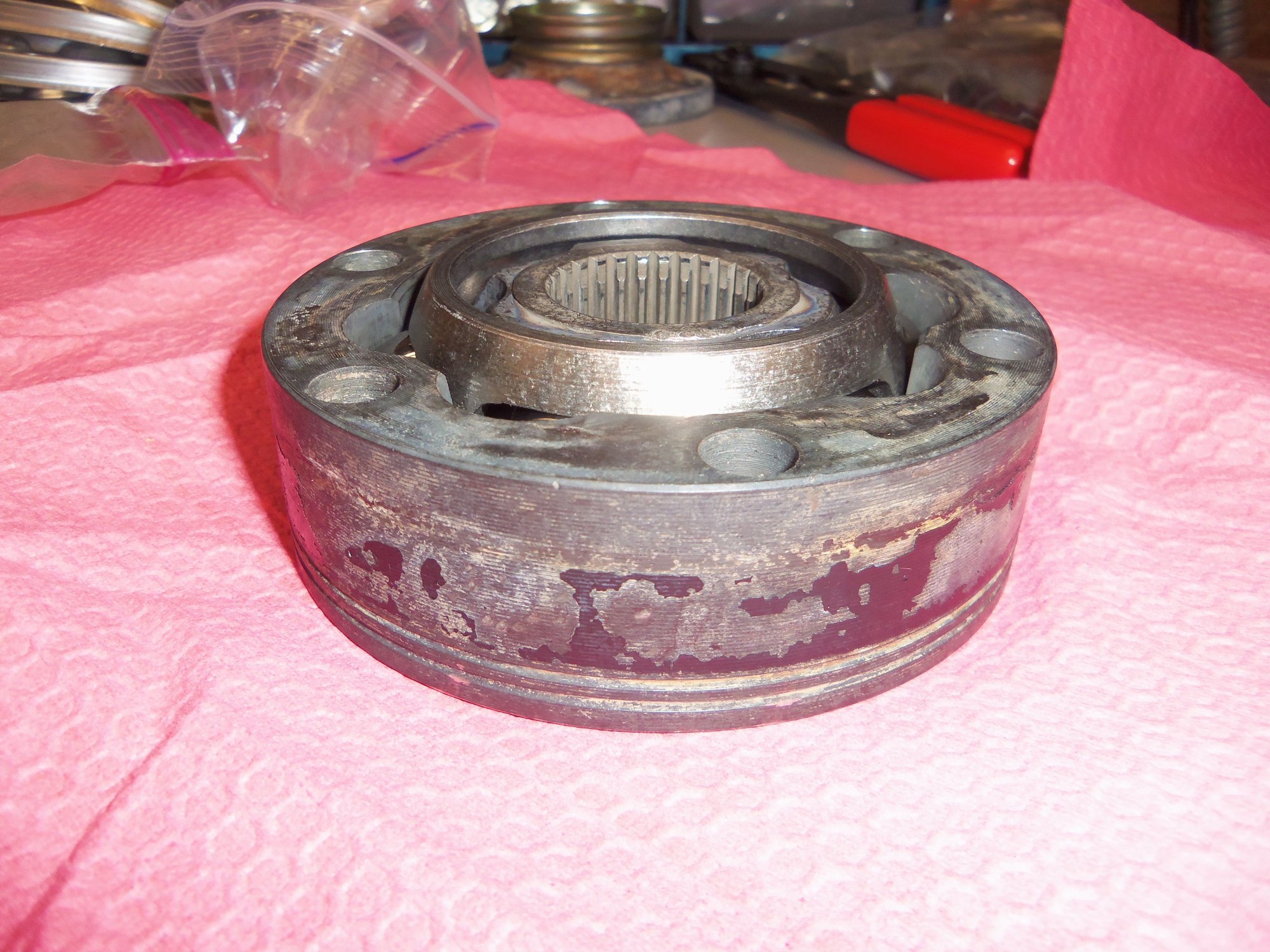
I REALLY wanted to keep the 68,*** mile CV axles. However, I received(and heeded) advice that the hub with the casting flaw should not be used.
The passenger's side complete inner CV joint has been wrapped up and bagged. I will decide what to do with it later. I can't quite bring myself to throw it away yet. Yes, I know it is useless.
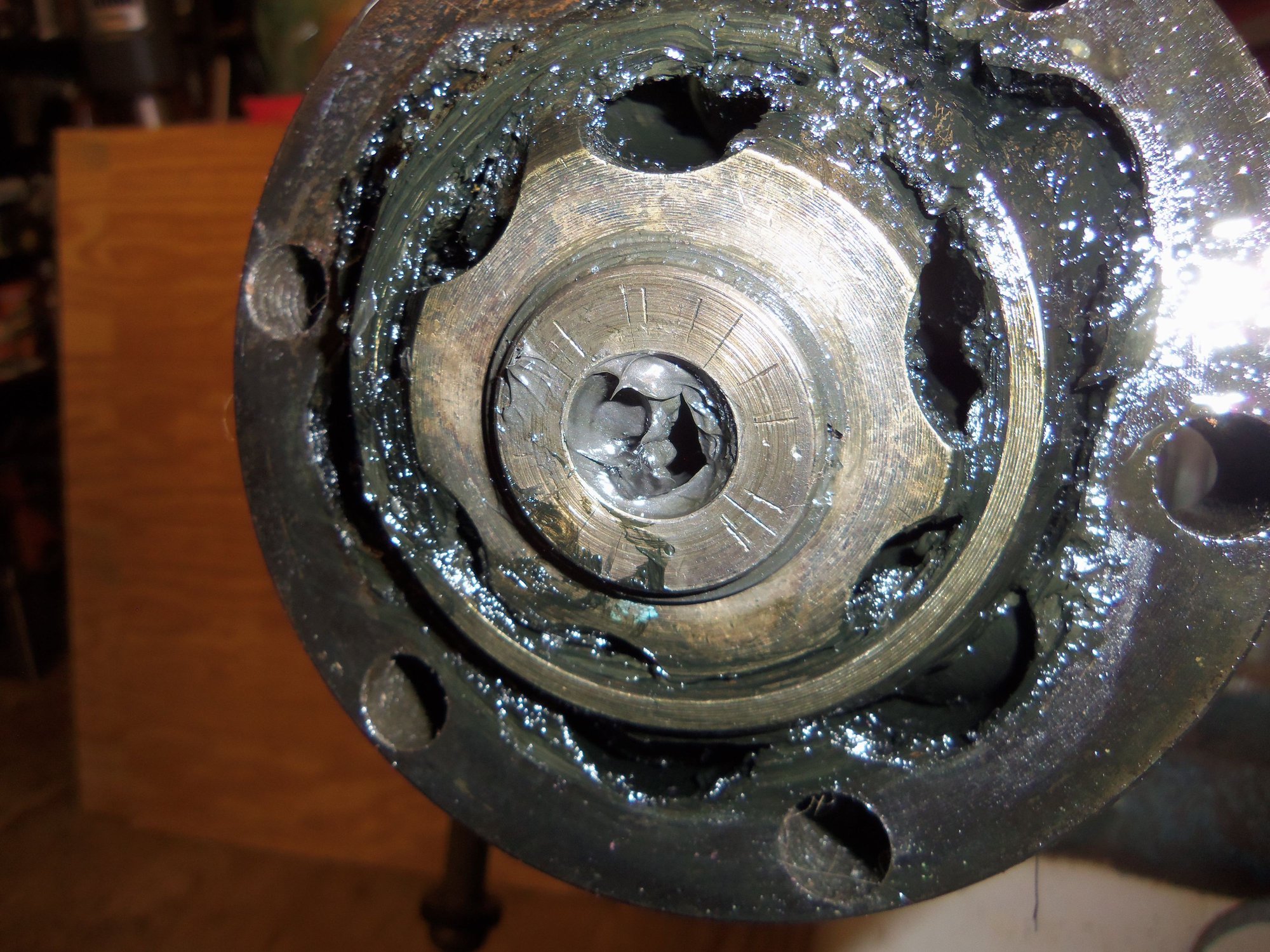
I said complete CV joint because I am NOT going to just get another hub. All the *****, hub, and body are wear matched to each other. I am going to get another complete inner CV joint and go from there.
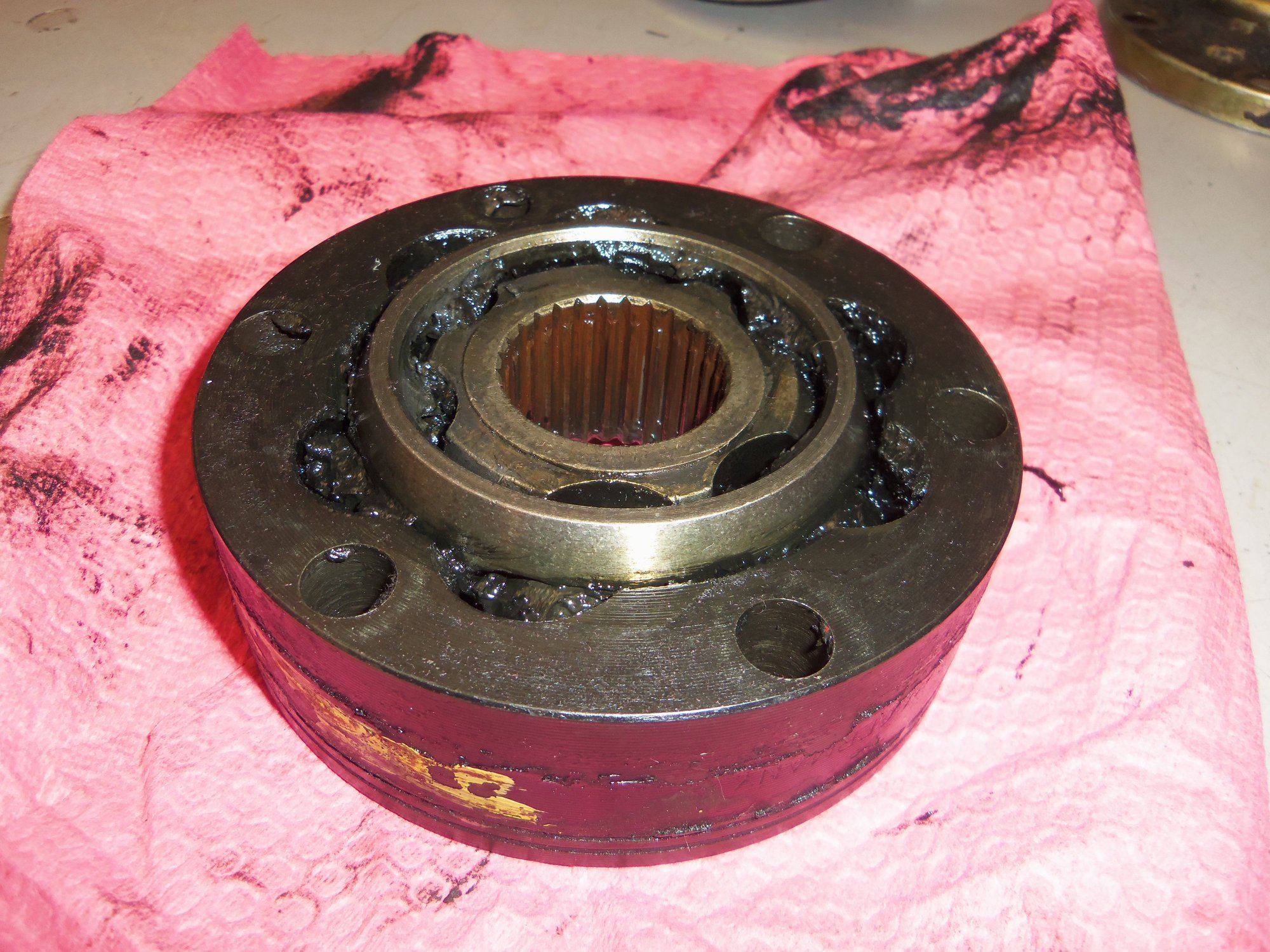
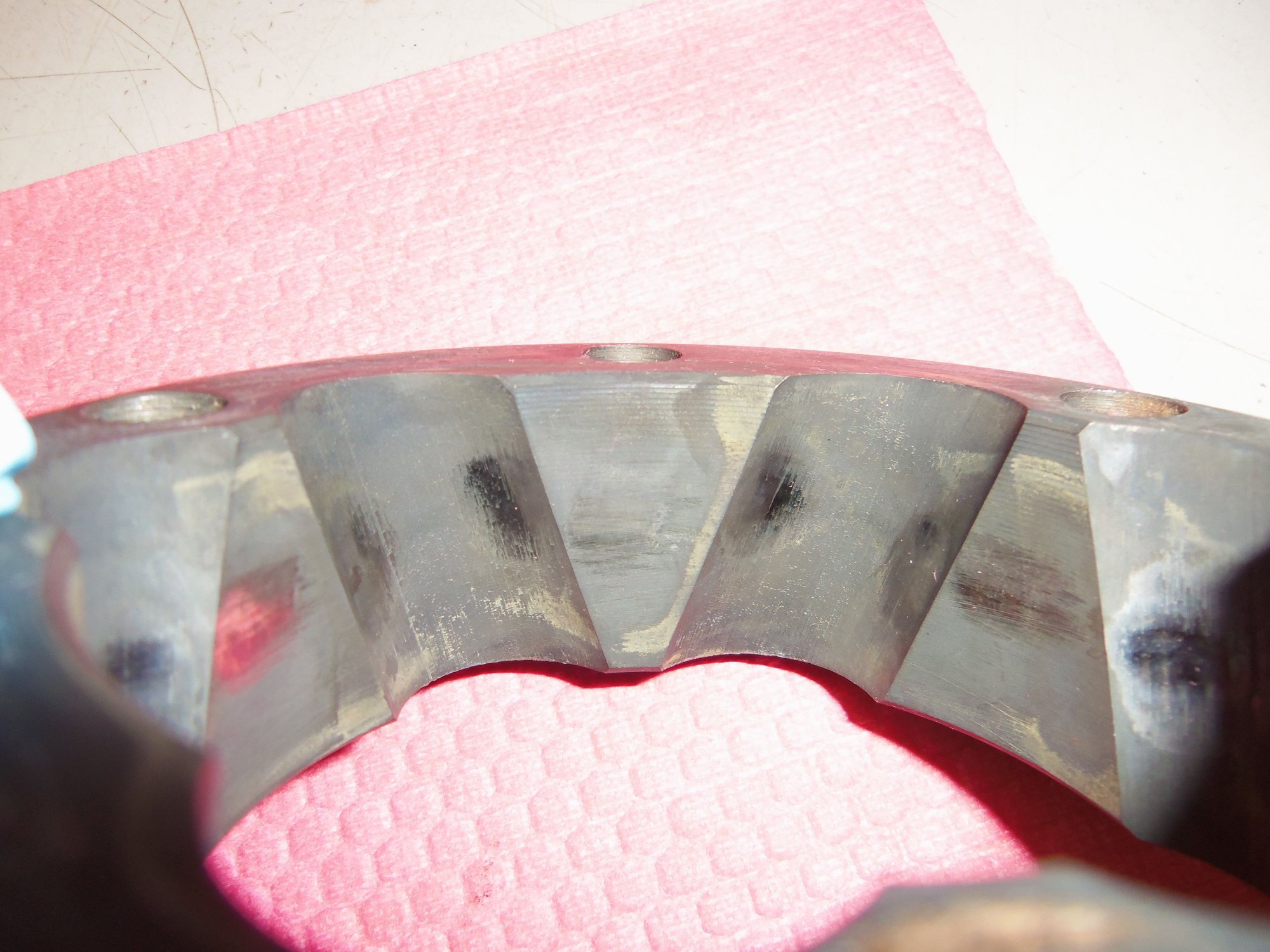
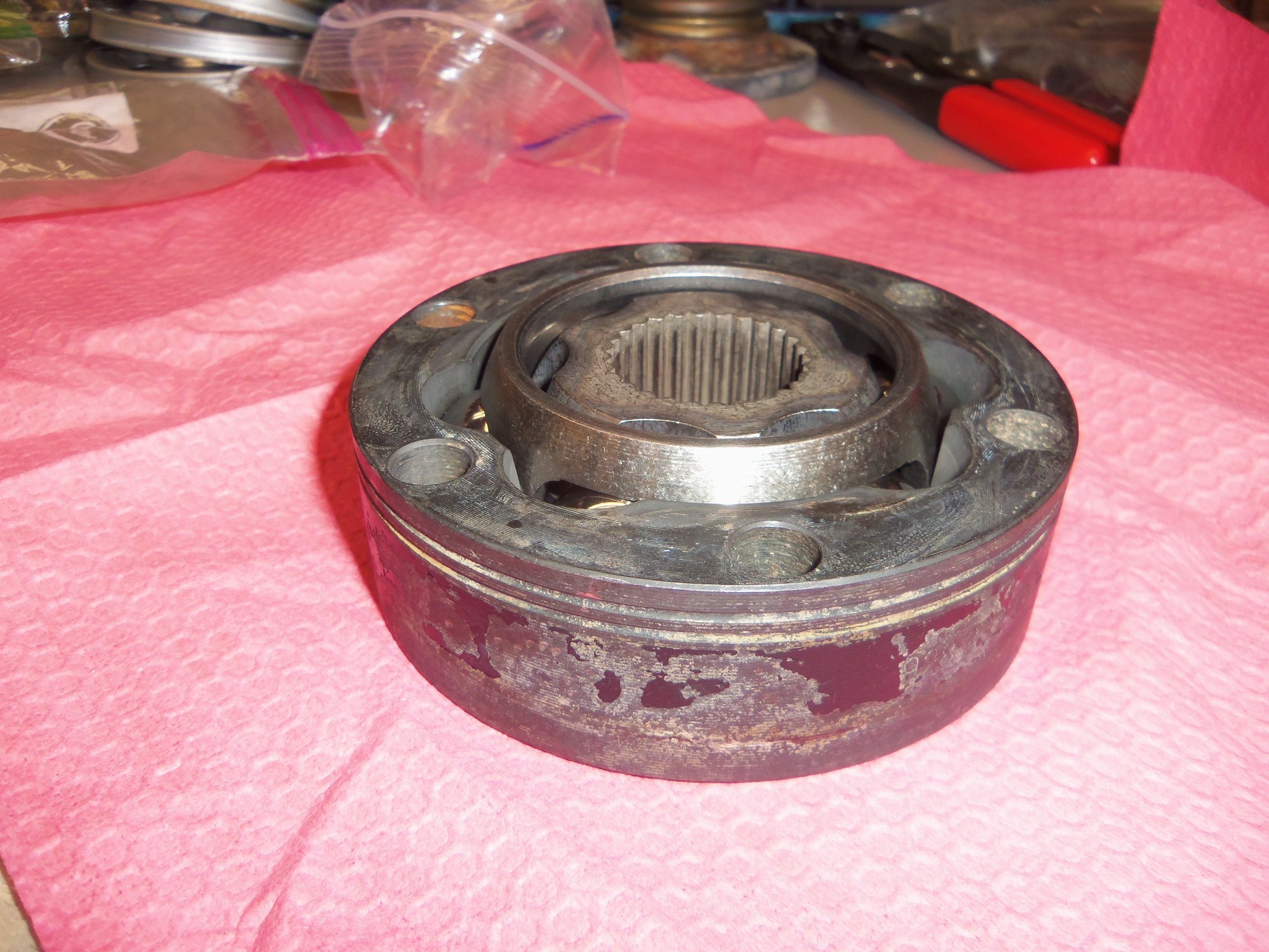
No wear or damage on any of the six ***** from this CV joint.
Luckily, I still had both orginal CV axles that came out of the Red Witch. They seemed OK when I removed them. I have receipts where they were relubricated and rebooted 20 some odd years ago. Meaning they should be in OK enough condition. Sucker.
I removed the inner CV joint from the original passenger's side axle using the same methods as the earlier axles. Except it went to work with me one night to use one of the hydraulic presses in Tool & Die to remove the CV joint from the axleshaft.
After cleaning, this joint was inspected. The wear was a tad more than from the 68,*** mile CV joints. I wasn't overly concerned, because the Red Witch had 168,*** miles on her clock. More importantly, I found no defects in the hub. So I now had a good CV joint to reassemble.
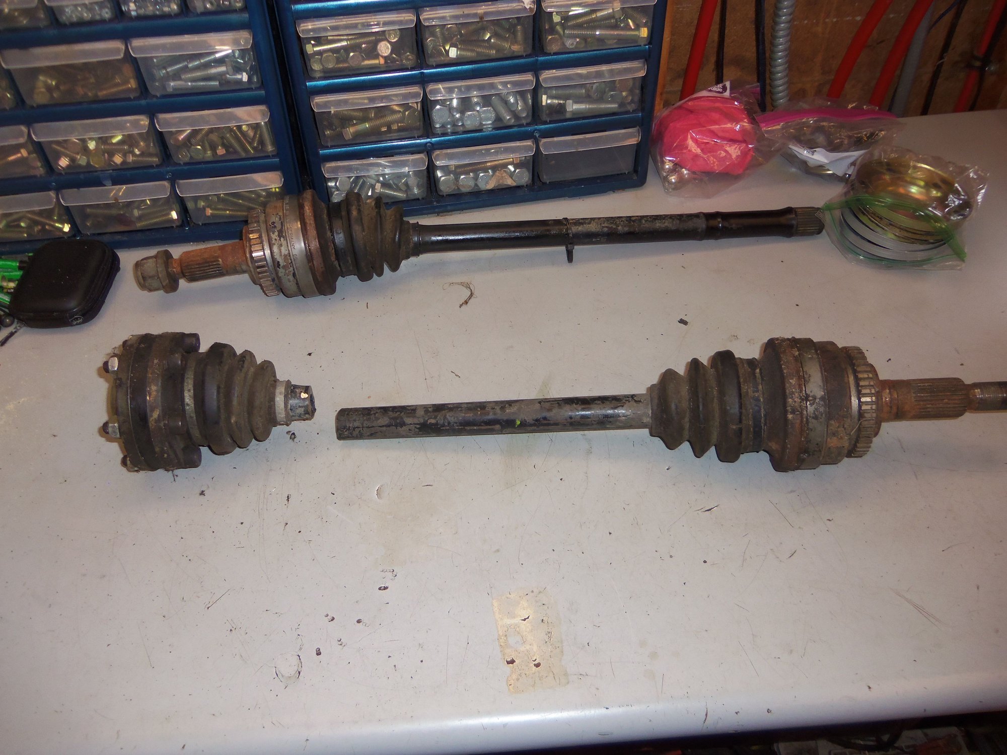
Original passenger's side CV axle assembly from the Red Witch.
Grease is still good.
Inner CV joint cleaned.
A little more wear, but no casting defect.
Why did I specifically get the inner CV joint from the original passenger's side axle? Because I am putting it on the donor passenger's side axle. I am swapping the driver's and passenger's side CV axles side to side when I install them. I heard whispers of an old wive's tale on Rennlist. When refurbishing your CV axles. swap them side to side. The load surfaces will be reversed. IE, the car spends more time going forward than reverse.
Yes, this is in the realm of question, but seems reasonable enough to me. And it is already done.
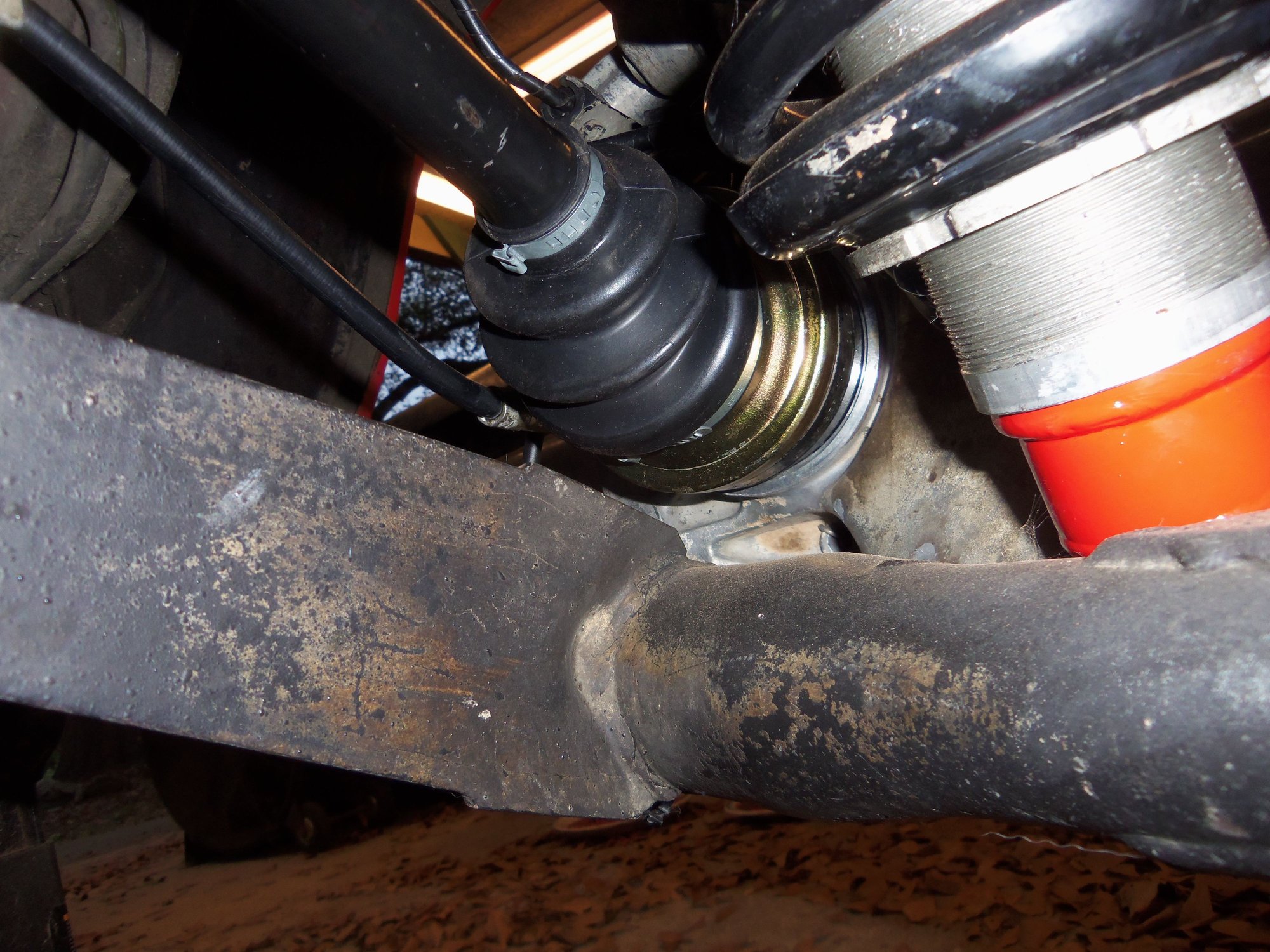
Inner CV joints removed from the axleshafts, I then removed the boots on the outer CV joints and got a look inside. More old grease and nothing obviously wrong. I wiped out as much grease as I could.
Driver's side outer CV joint pushed down.
Driver's side outer CV joint pulled up.
Looking inside the open cap on the driver's side outer CV joint.
Passenger's side outer CV joint pushed down.
Passenger's side outer CV joint pulled up.
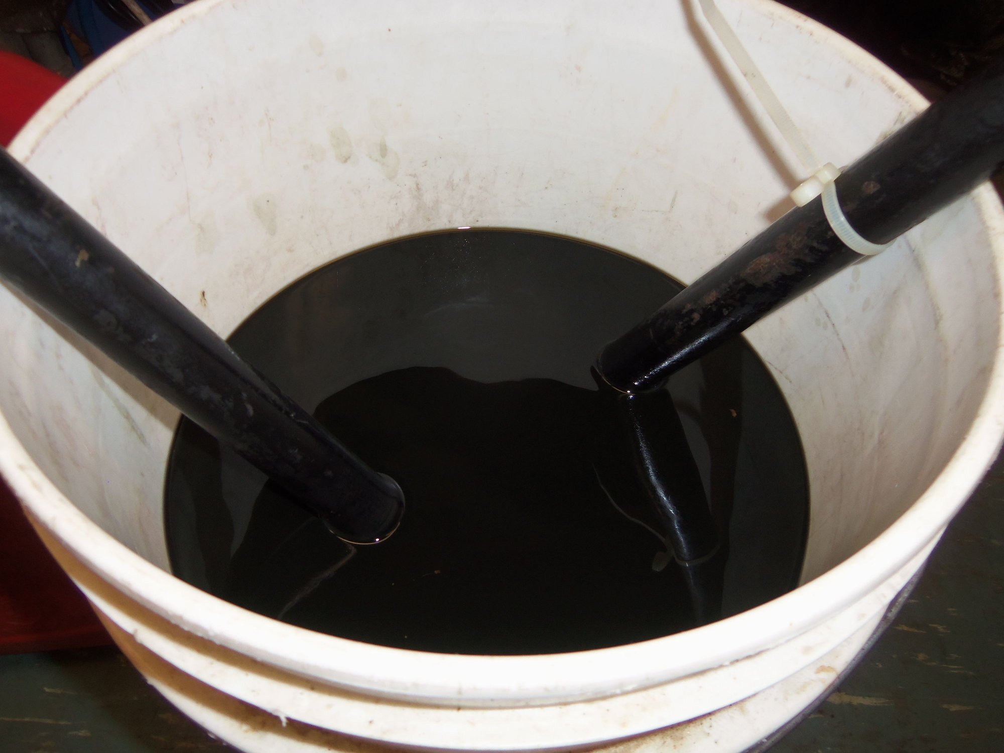
Now comes the nasty part: cleaning the axleshafts and outer CV joints.
All I have read says this is a horrible, nasty job. You will get grease all over yourself, your work area, your car, your cat, your neighbor, and penguins will die.
Yeah...
In the thread about refurbishing the later S4 axles, someone mentioned soaking the outer CV joints in a bucket of gasoline. Someone else mentioned running air down the axleshafts to agitate the solvent.
BINGO!
One 5 gallon bucket, three gallons of cheap gas, and two CV axles later, I had a cleaning rig. In a bit of serendipity, I found a 1/4 NPT pipe nipple fit perfectly down the bore in the axleshafts. I rigged up a male quick connect and a length of copper pipe. Put the pipe down the axleshaft, add a couple PSI air pressure, and I had a bubbler!
I let the bubbler bubble for around an hour per axleshaft. Throughout the hour I would occasionally move the joint around. After the hour for each, I dumped and refilled each outer CV joint back into the bucket. I did make a bit of a mess there, forgetting the hole goes all the way down the axleshaft, and spilling a little dirty gas.
NOTE: while the bubbler was bubbling, it was aerating the gasoline and producing vapors. IE explosive mixture. I had a pedastal fan several feet away blowing the vapors away towards the woods.
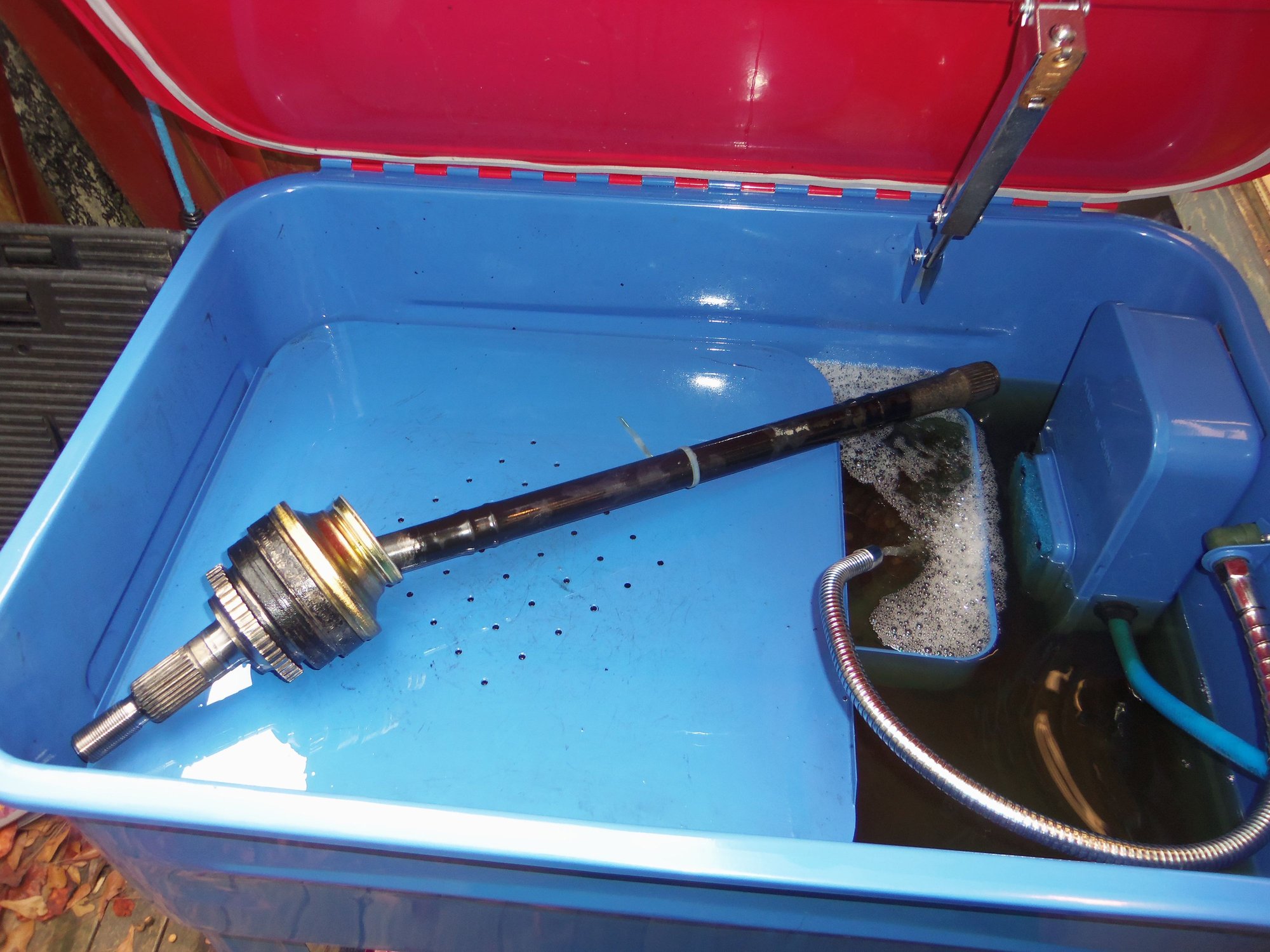
From the gas bucket, each CV axle went into my parts washer for scrubbing and flushing. Followed by a thorough rinse out with brake cleaner.
Axles in a bucket.
Cheap and cheerful cleaning solvent.
Grease makes solvent dirty quite quickly...
Impromptu air nozzle.
1/4 NPT pipe fits perfectly in the axleshaft bore.
Air connected.
Bubbler bubbling.
Cleaning and flushing in the parts washer.
Final rinse with brake cleaner.
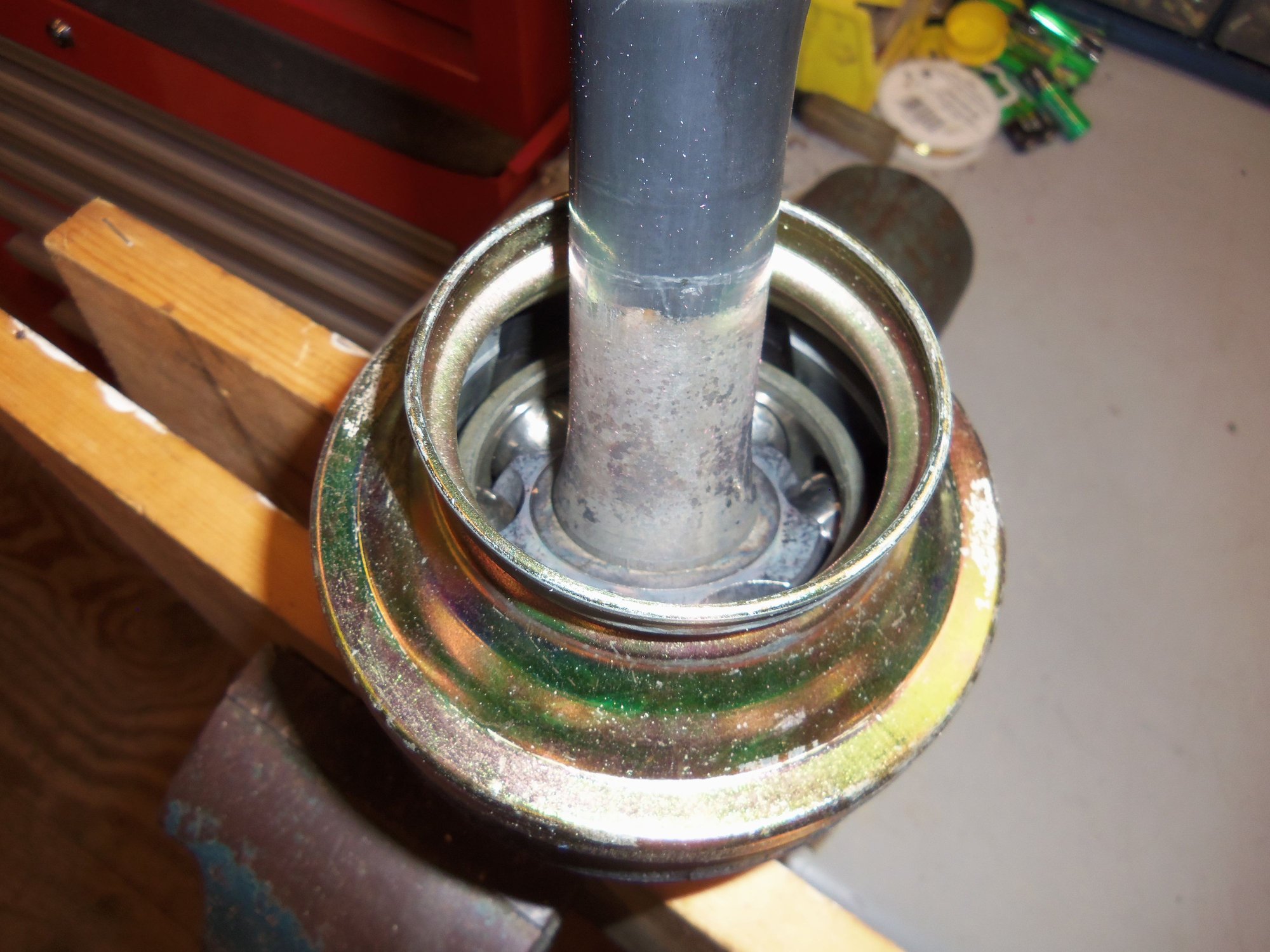
I inspected both clean outer CV joints as best as possible through the opening in the inner cap. I moved the joint all around, plunging it in and out. I saw no obvious damage or major wear. Good enough for me, and crossed fingers to go forward.
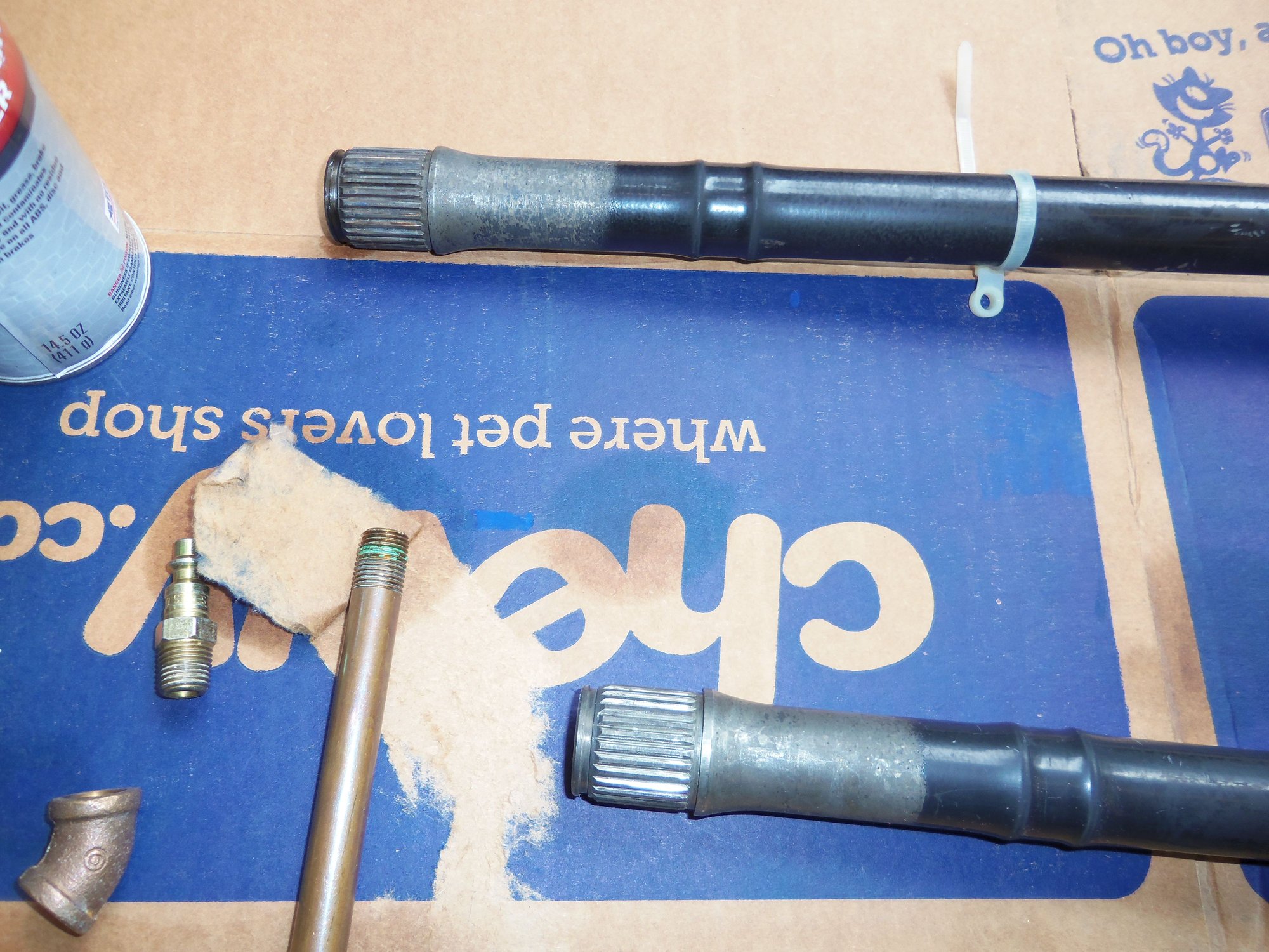
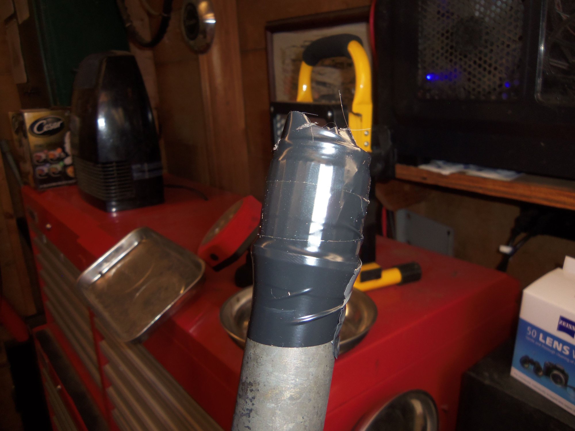
To fill the outer CV joint with grease, I chucked it up in my vise, with wood on the hub splines. The joint and axleshaft stayed vertical. I wrapped the splines and snap ring groove at the top of the axleshaft with electrical tape. This was to allow the boots to slide over and not get cut.
I squirted one full pack of grease into the outer joint. Then I used my finger to smoosh the grease down into the joint. I was able to add another half pack of grease. Then I tried the tip from Dwayne and Greg Nichols to suck the grease into the joint. I suck. And screwed it up.
Turns out you are supposed to plug the hole in the splined shaft at the bottom AND the hole in the top of the axleshaft before you try to pull them apart. It works much better when you plug both holes. By doing that, I was able to get the remaining half pack of grease into the outer joint. Let me tell you, it is a bit of a b*itch trying to plug the bottom hole, plug the top hole, then try to pull the axleshaft up. It takes dexterity and strength.
Outer CV joint chucked up in the vise.
CV joint pushed down, ready to receive grease.
Splines and shoulder taped off on top of axleshaft so as not to cut the boot.
Grease, boot, and clamps for one CV joint.
Grease smooshed into CV joint.
Grease after being sucked into the joint.
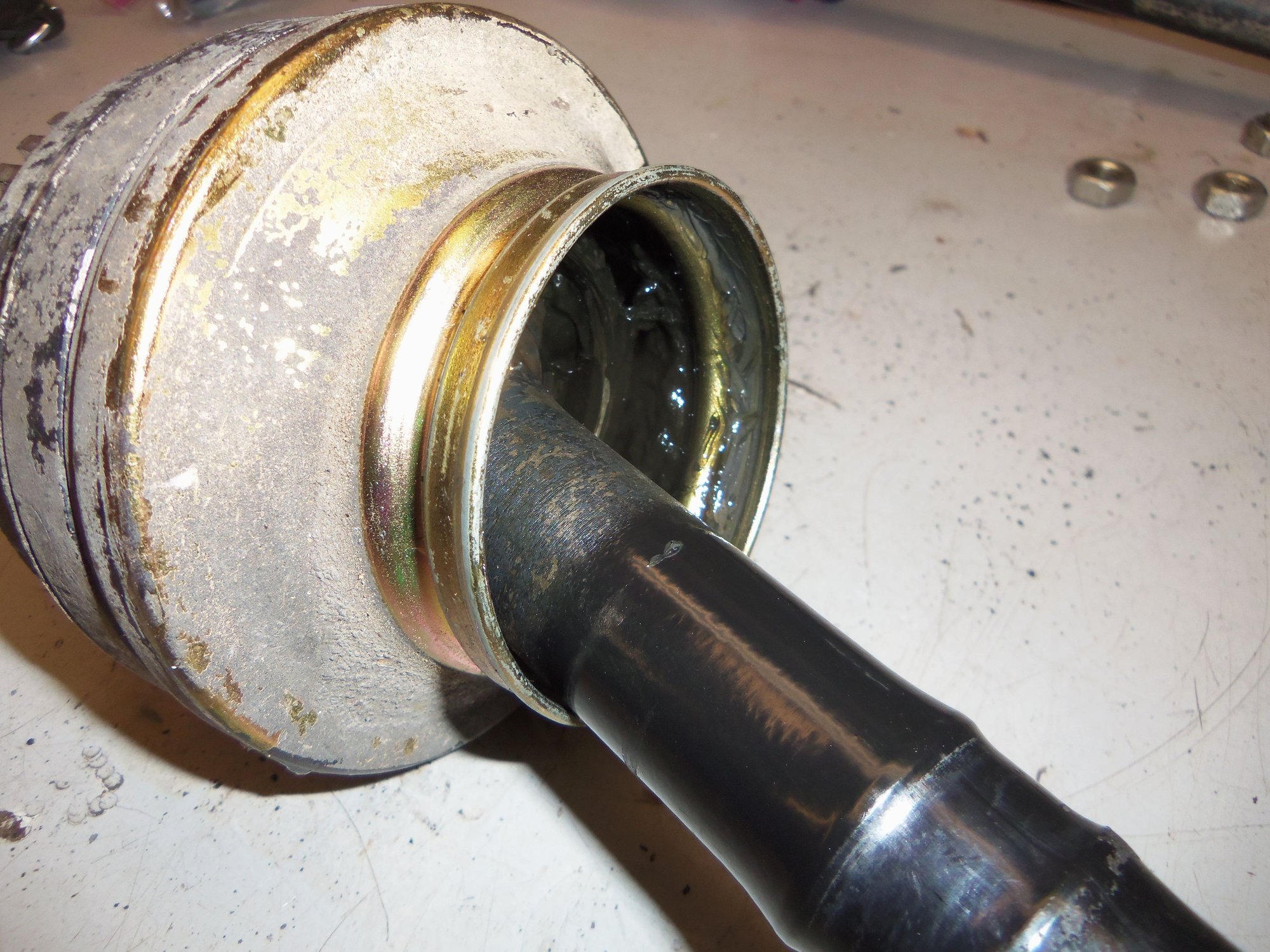
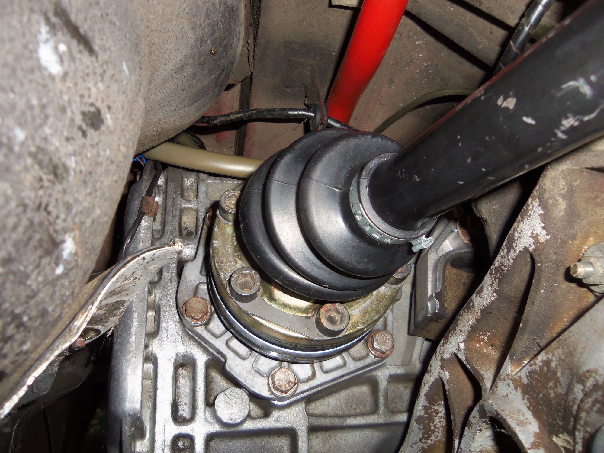
I ran a new boot down the axleshaft and seated it on the spigot on the inner cap. This took some doing and I had to use a stiff 90 degree pick to pull the boot over the last little bit of the lip. I left the clamps off because I thought the large one would prevent the boot from distorting enough to get over the lip of the spigot. I was correct. So, I disassembled the large clamp to get it around the large end of the boot, and then reassembled it in place.
The small clamp went right on.
The clamps are OET brand that require the center part to be crimped. Luckily, I have the proper tool for that. Thank you Greg Brown and all the OET clamps for the transmission cooling lines... 😄
In a little bit of OCD, I oriented both clamps in the same direction, then solidly crimped them.
Before I went any further and forgot, I installed the boots for the inner CV joints. I would be right pissed at myself for installing the joints and forgetting the boots. 😞
Dwayne mentioned the boots were easier to install on the inner cap spigots with the caps loose on the work bench. Easier is a relative term...
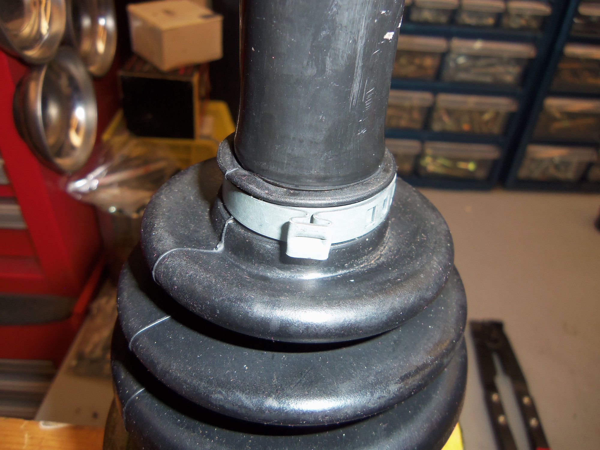
I got them on, again having to use a pick to get the boot over the last little bit of the lip. I put the large clamps on and crimped them down, ensuring the raised center crimp was between two bolt holes.
Then it was just a matter of working the boots down the axleshafts out of the way. AFTER putting the small clamp loosely on the axleshaft.
Clamps as they go on the boot.
Using a 90 degree pick to help get the boot over the lip on the inner cap.
Boot seated, clamps loosely installed.
Proper clamp crimping tool.
Upper clamp crimped.
Lower clamp crimped.
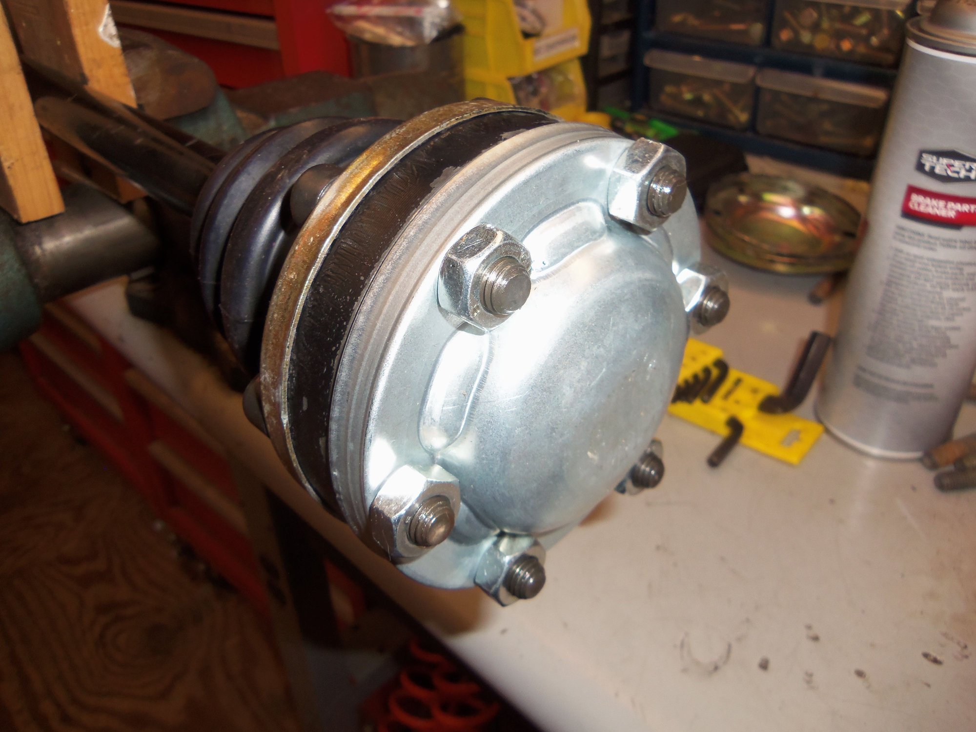
Completed outer CV joint.
Inner CV joint open caps, boots, and clamps.
Boots and clamps crimped to open caps.
Inner CV joint boot and open cap pushed down axleshaft. Note small clamp was put on first.
Now the axleshafts got clamped horizontally clamped in the vise with wood.
Following Dwayne's write up, and the WSM, I got each inner CV joint reassembled. First one took three tries. Second one only took two. Progress! I was careful to ensure the hub and body were aligned as per my earlier photos. The later axle thread implies the CV joint won't seat properly on the axleshaft if it is backwards. Won't be able to get the snap ring on. I didn't want to find out.
Looking at my photos, I figured out what they were talking about. The splines are undercut at the raised boss side of the hub that goes up against the shoulder on the axleshaft. Because, that undercut area goes OVER the edge of the shoulder. Looking at the hub installed on the shaft, the shoulder raises up to smoothly meet the hub. Looking at the shoulder with the hub removed, there is an edge that goes into the hub. Putting the hub on backwards would mean the hub would not go far enough to expose the snap ring groove.
Good to know.
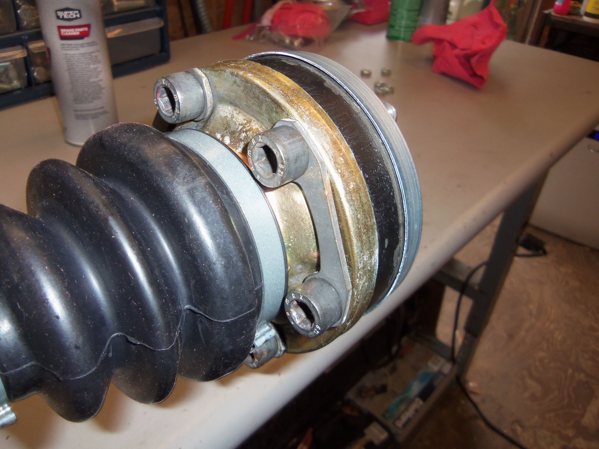
Assembled inner CV joint. Note how the Narrow point formed between two ball races on the hub lines up with the wide point formed between two ball races on the body. And vice versa. This alignment is what allows the CV joint to flex.
Raised boss side of hub lined up with corresponding no machined rings side of body. Note the undercut area of the splines inside the hub.
Smooth side of hub lined up with corresponding machined rings side of body.
Supporting the body of the CV joint, I started the hub on the splined end of the axleshaft. The first one slid on most of the way. I used a 1 1/4" 12-pt socket and a hammer to tap the hub the rest of the way until it was seated. I was careful to support the joint body so it didn't **** and start dropping *****.
The second one started on the splined end of the axleshaft and only went a third of the way. I had to tap it the rest of the way to seated.
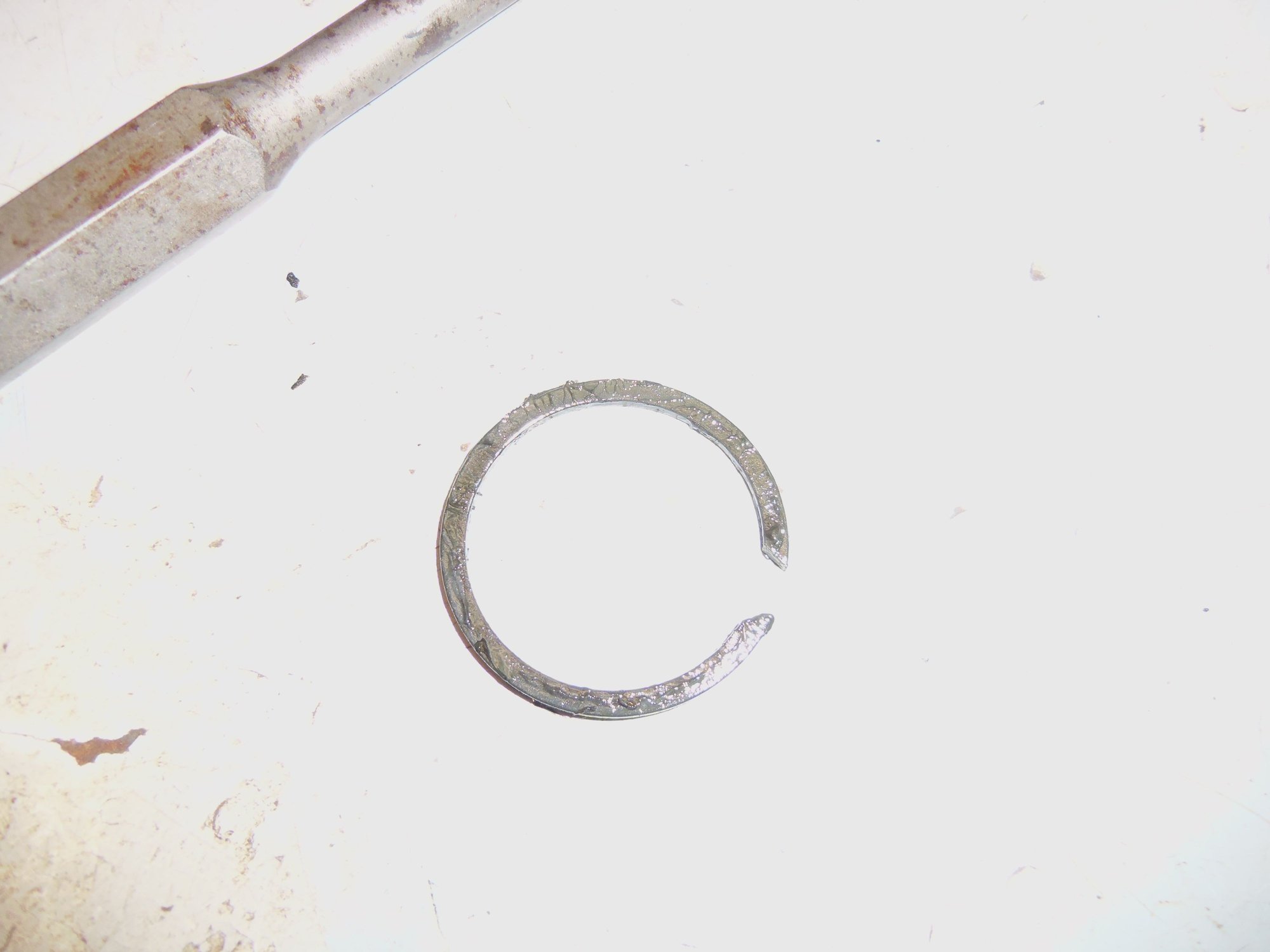
Followed up with installing the new snap rings. I used the new ones because they were new. I have kept the old ones, as I don't necessarily think there is anything wrong with them. And I am more comfortable installing snap rings with ears.
Tapping hub onto axleshaft.
Hub seated and snap ring groove visible.
Snap ring groove.
New snap ring with ears installed. Because that is what I am comfortable with.
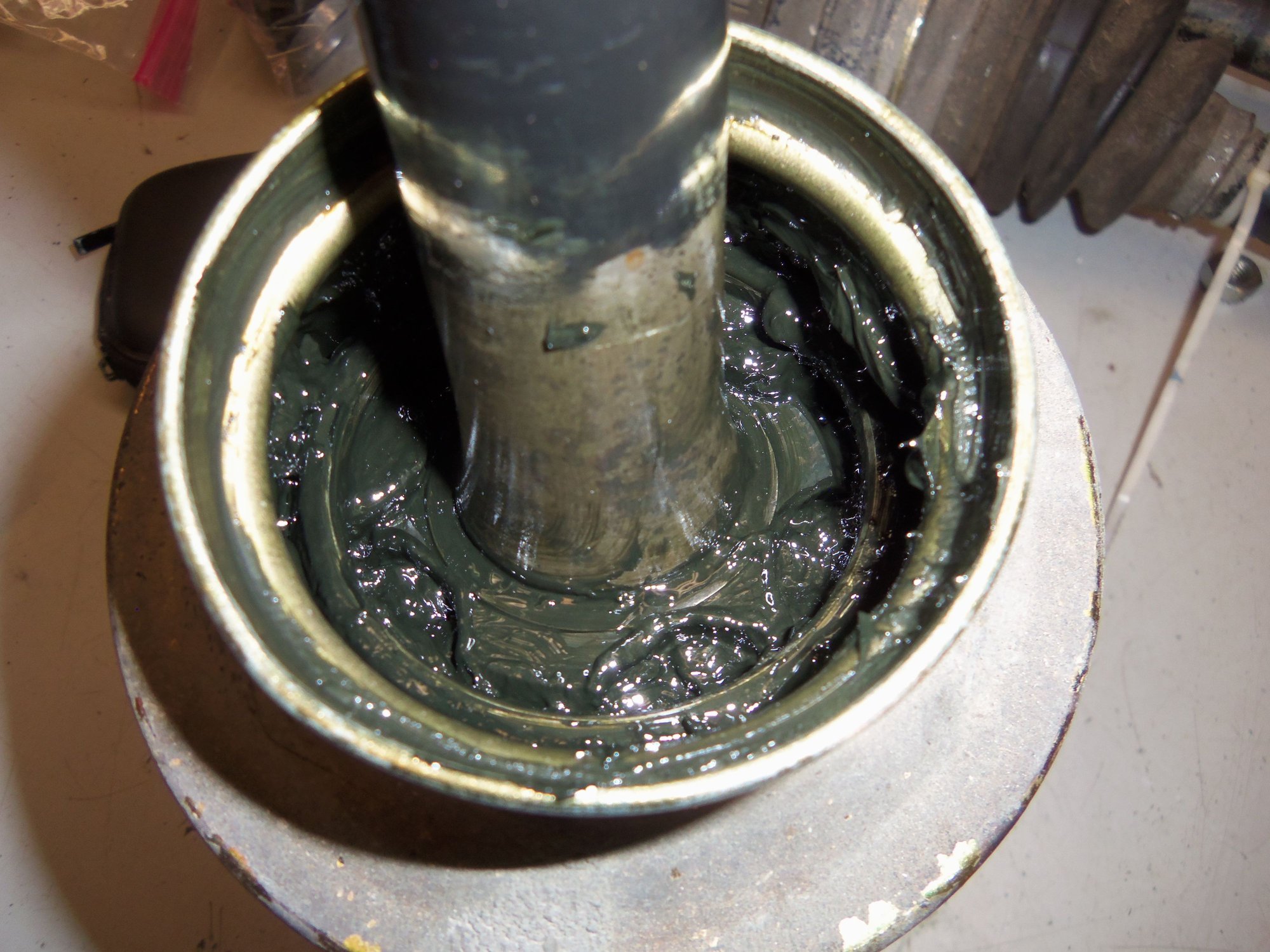
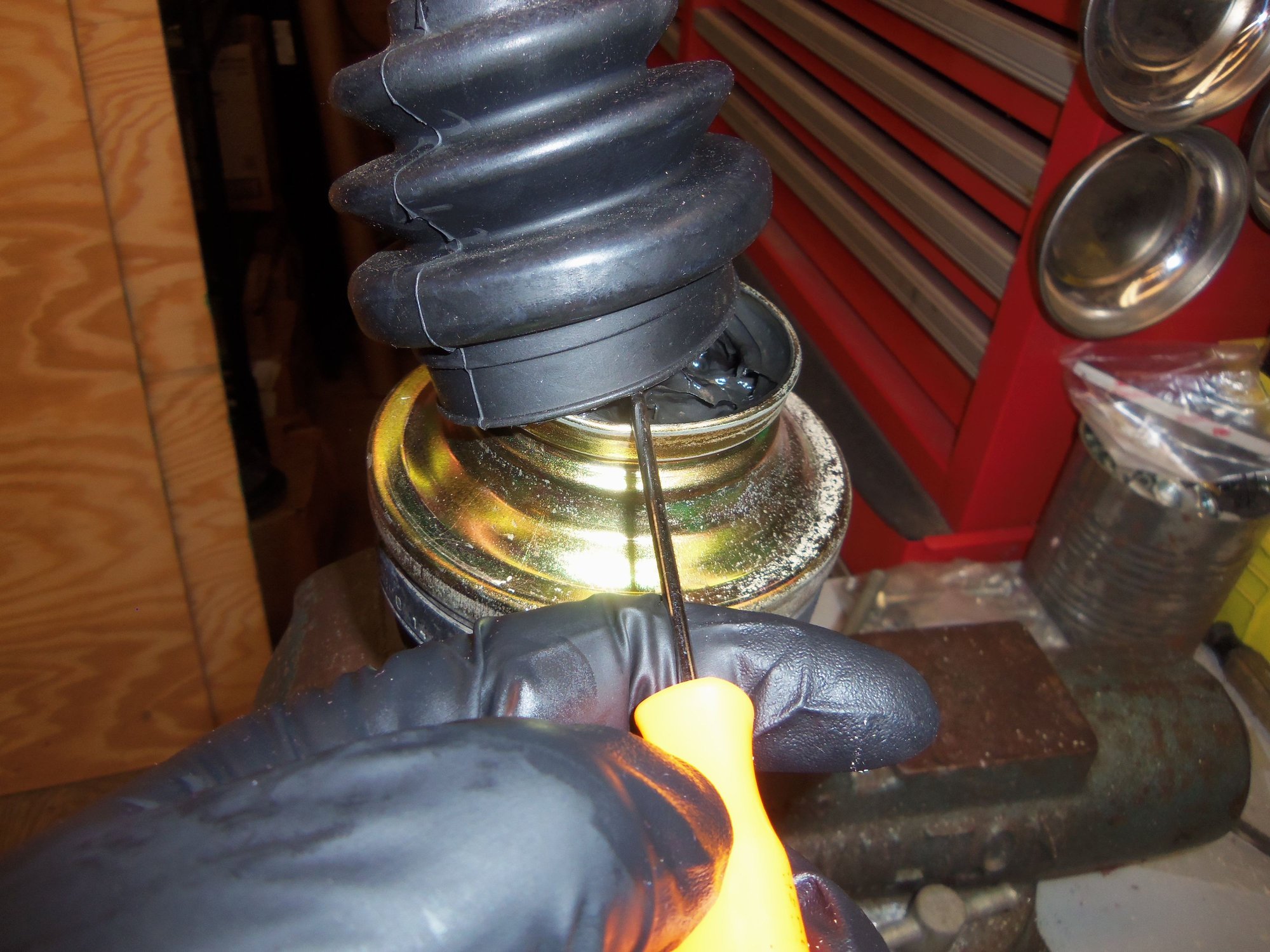
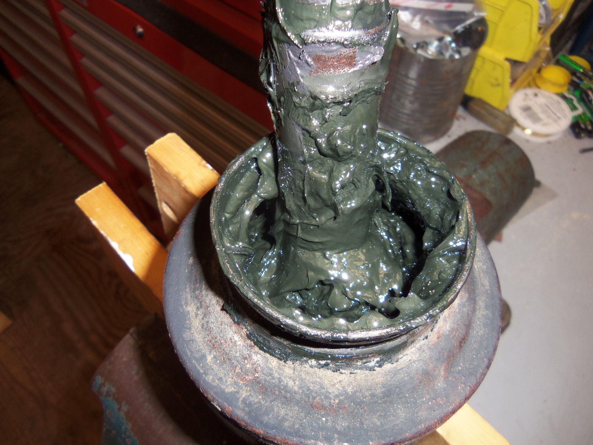
Another possibly nasty part: adding grease to the inner CV joint. Various sources report only being able to get 1 3/4 packs of grease into the joint. I was determined to get both packs in. And I did.
I started off with the boot side of the inner CV joint.
I pulled the joint as far away from the hub as I could. By only cutting a tiny corner of the grease packet, I was able to squeeze out a narrow stream of grease. I directed this stream into the ball pockets in the body, and around the hub. Then, I pulled the joint as far onto the hub as I could. Then I could stream grease into the ball pockets on the hub. I squeezed the last of the pack of grease into a heap around the hub.
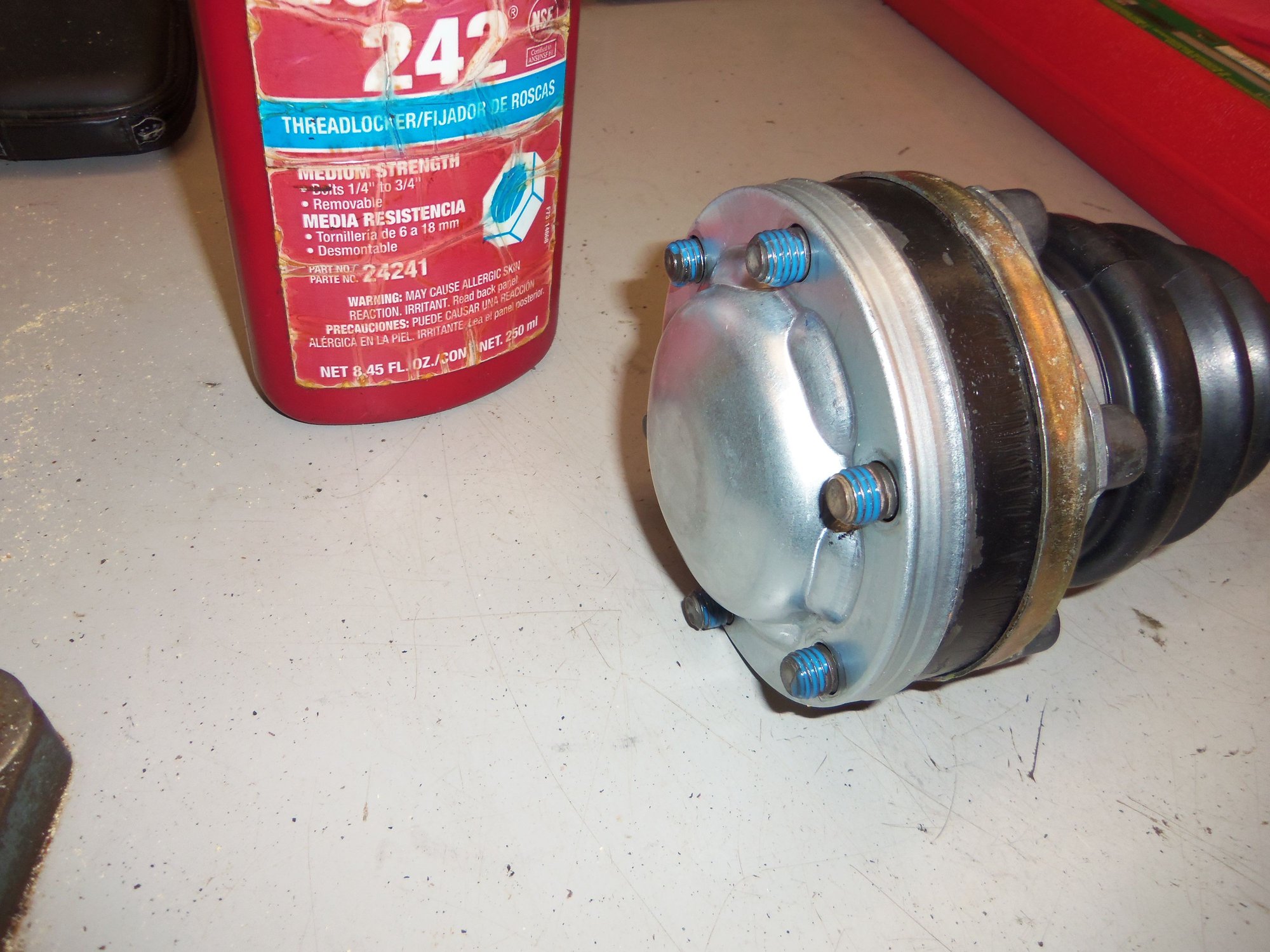
I very gently pulled the boot and inner cap onto the CV joint, lining up the bolt holes. I put the six bolts in the holes and nuts on the threads that protruded through the backside of the CV joint. I evenly tightened the nuts to draw the inner cap onto the CV joint body. I didn't crank down on them, just wanted to get the cap started.
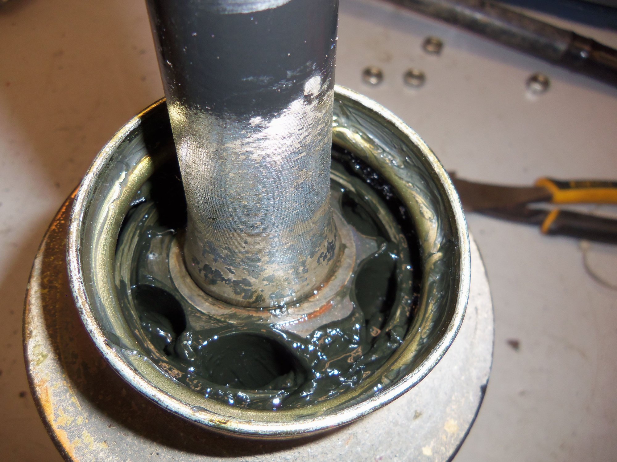
I left the nuts and bolts in while I used the same grease technique to put the full second pack of grease into the back side of the inner CV joint. I squeezed the last of the grease into the center of the end cap.
After removing the nuts, I started the end cap and put the nuts back on. Same thing of evenly tightening the nuts to draw the end cap on the CV joint body.
Last step was to remove the bolts and nuts, clean the bolts, then reinstall them with the three stiffening plates.
One CV axle done!
Repeat as necessary for the other one.
Front side of inner CV joint packed with grease.
Boot and cap pushed down to CV joint body.
Bolts pulling cap onto the body.
Back side of CV joint full of grease.
Last of the grease in the end cap.
Bolts and nuts pulling the end cap onto the CV joint body.
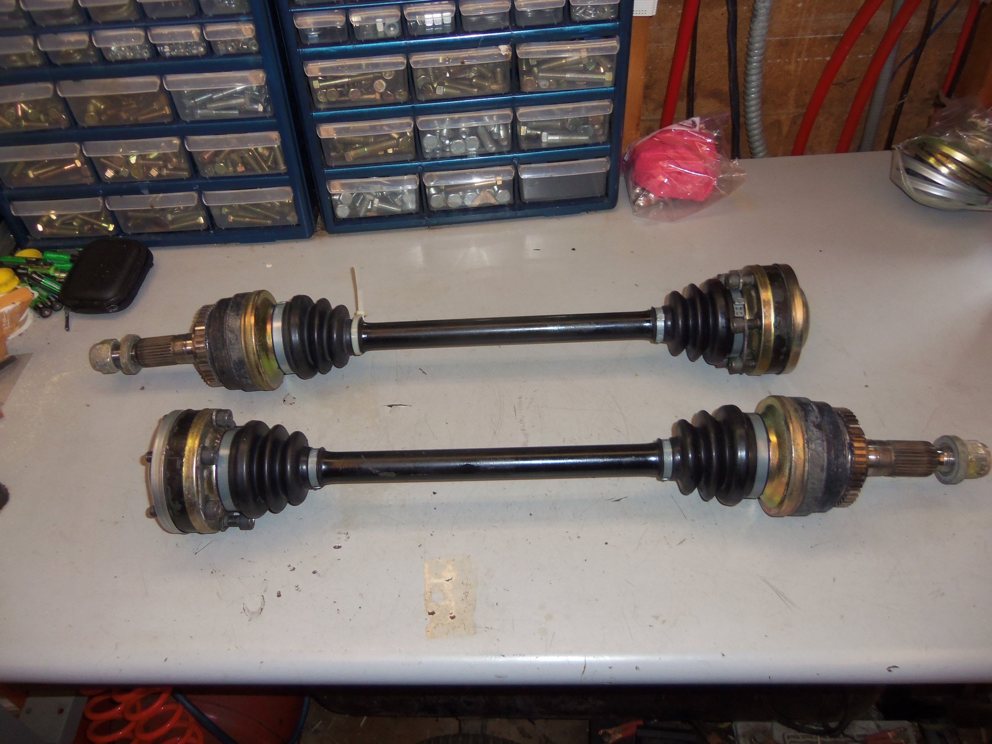
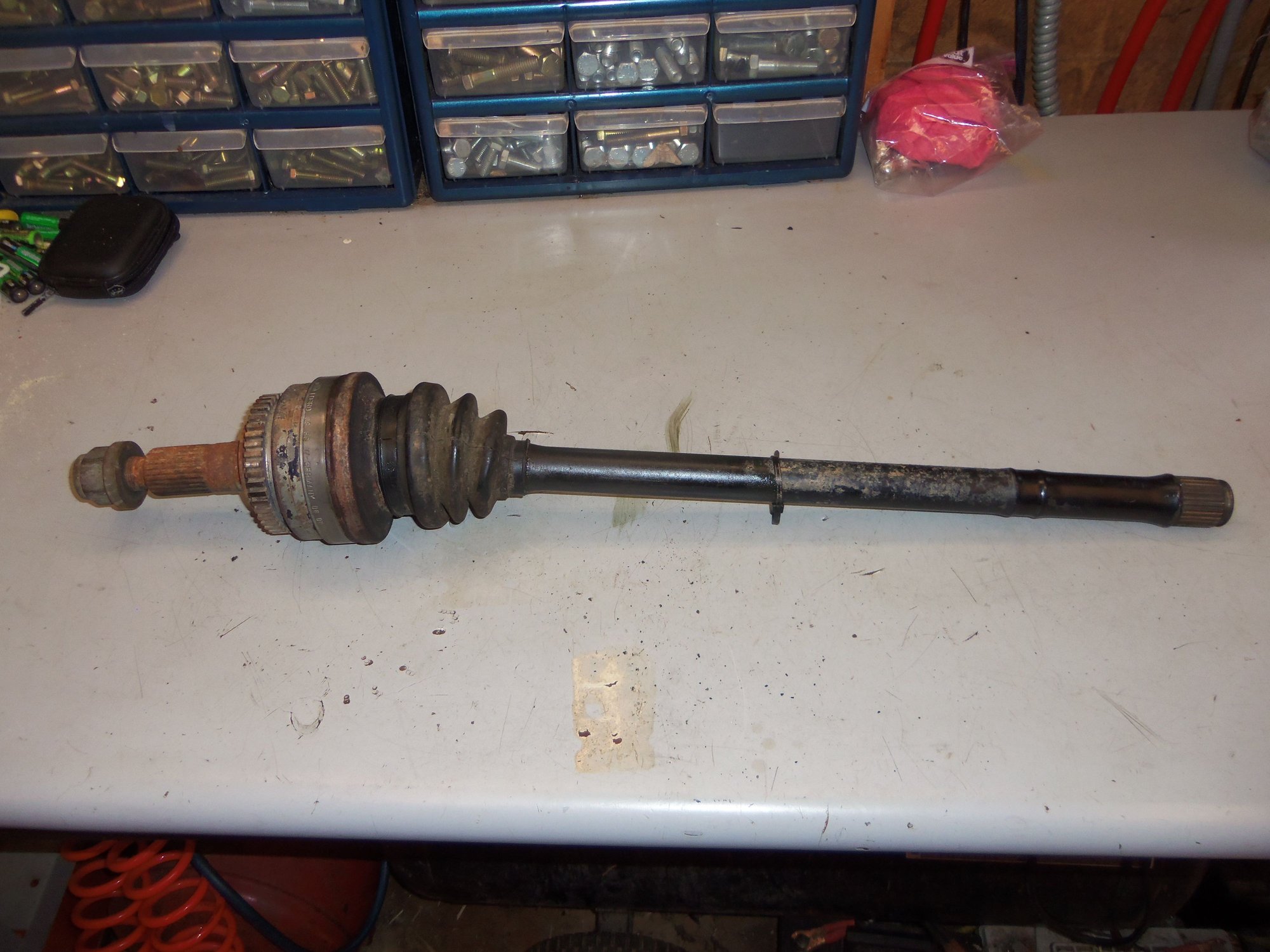
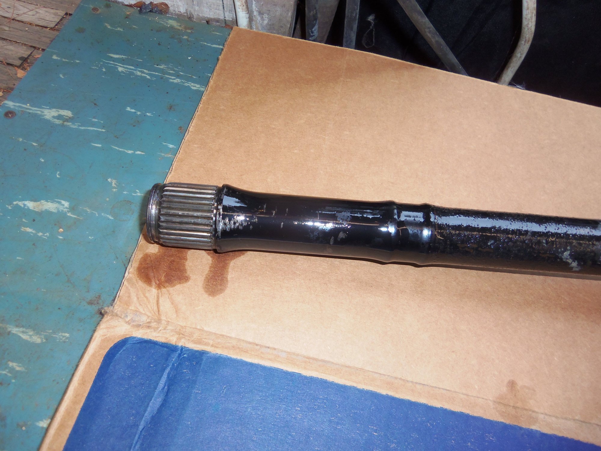
Refurbished CV axles. Disassembled, cleaned, inspected, lubricated, and resealed.
Now, I had two refurbished CV axles, and 1 1/2 spare CV axles. I figured I would inspect them for condition.
The passenger's side axle outer CV joint was OK. The outside was dirty and a little corroded. The threads and hub splines had a little surface rust from improper storage(me = idiot.) The boot was intact. Removing the boot revealed a CV joint full of old grease and no obvious damage.
OK, this one is good for future use. I put the boot back on then sprayed the entire outer CV joint, hub splines and threads, and other splined end of the axleshaft with CRC 3-36 protectant. Once that dried, both ends got wrapped in rags, then bagged and ziptied.
I will refurbish this axle in the future if necessary.
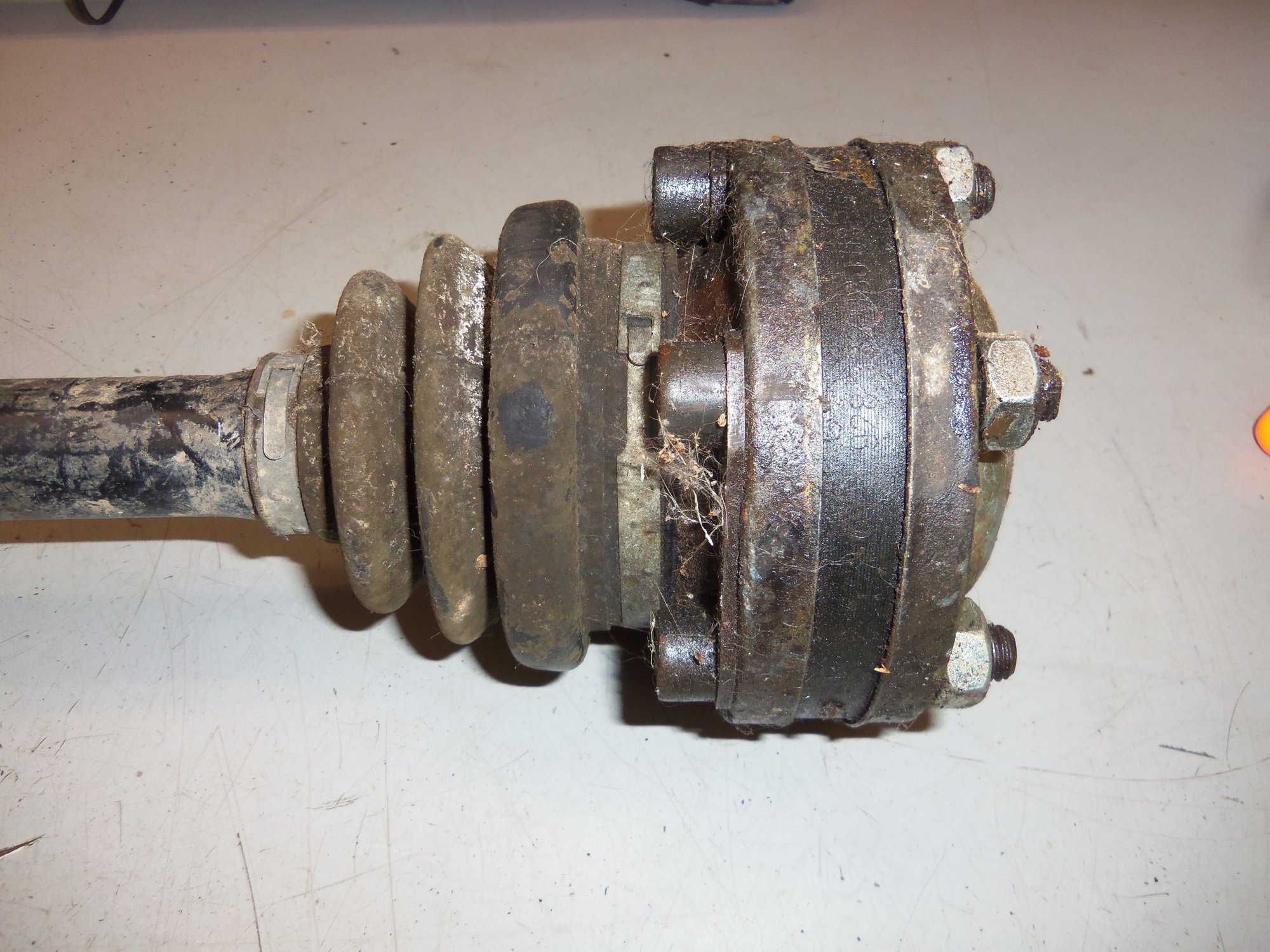
Original passenger's side outer CV joint pushed down.
Joint pulled up. Grease is still good.
Dirty 1/2 CV axle assembly, original passenger's side from the Red Witch.
Splined end of shaft looks good.
Surface rust because of improper storage. Bad Seth, bad!
At least the rust is not all encompassing.
Outer CV joint sprayed with CRC 3-36 in an attempt to prevent further corrosion while in better storage.
The driver's side CV axle...
I pulled the boot from the inner CV joint as was met with old grease and no obvious damage.
Warning bells started ringing loudly when I examined the outer CV joint. To be blunt, someone cut the inner cap off then welded it back on. Both parts being done poorly.
Removing the boot revealed a joint with far less grease and far more corrosion and debris than it should have. This joint is done. Pass it on to the waitress.
Original driver's side CV axle assembly from the Red Witch.
Inner CV joint doesn't look too hateful.
The outer CV joint doesn't look so good.
Ummm...this looks worse.
Yikes!
Not a good portent of what I will find inside.
Nope.
So...I cut the axleshaft just before the inner CV joint. Saves me the effort and mess of disassembling it for removal. Plus the grease is still in there as corrosion protection. The inner CV joint got sprayed with CRC 3-36, wrapped in a rag, then bagged and zip tied.
The remaining axleshaft and outer CV joint went in the metal scrap tub.
Easy way to salvage the decent inner CV joint for later refurbishment.
Axleshaft is thicker than I expected.
Back to the good axles. In the interest of corrosion protection, I sprayed both inner CV joints with CRC 3-36. I stopped at the boot and at the hub splines. Once it was dry, I wiped off the ABS tone ring teeth with brake cleaner on a rag.
Attempted corrosion protection.
For installation, as per the WSM, the threads and hub splines were coated with Optimoly HT. As per recommendations on Rennlist, the mounting bolt threads were coated with Loctite 242 blue medium strength thread locker.
The good stuff.
I made sure there was no grease on the bolt threads before applying the Loctite.
Getting the CV axles mounted back into the car was more of a challenge than I expected. Silly me...
I forgot the differential output flanges are behind the rear wheel hub centers, and the CV axles had to snake through various things. I got them, though. You would think getting the hub spline shaft through the splined hub would be no problem. Not with me. Took a fair amount of wiggling and turning until it all lined up and slid home.
Methodically and evenly tightening all twelve inner CV joint mounting bolts was also a pain and time consuming.
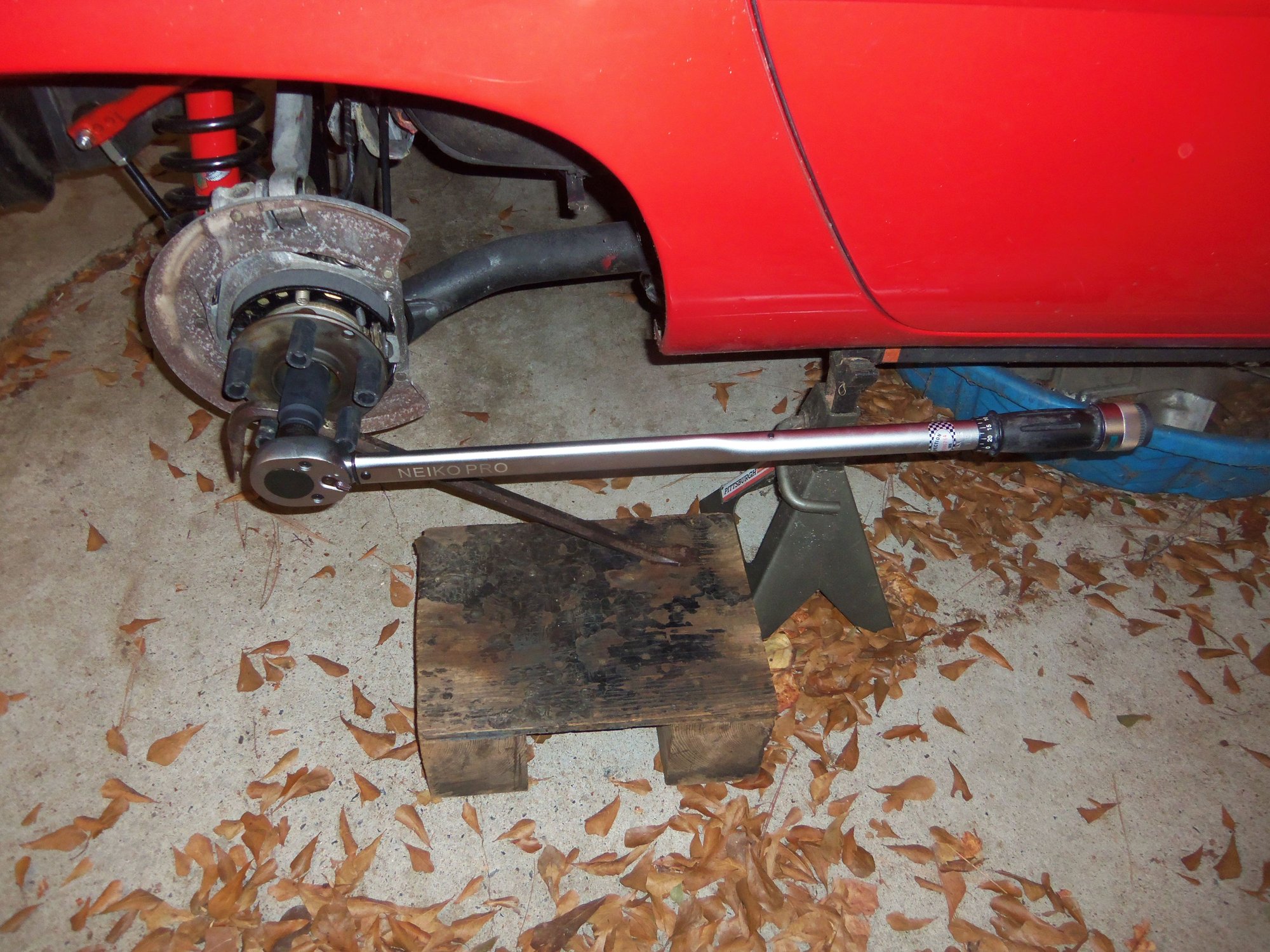
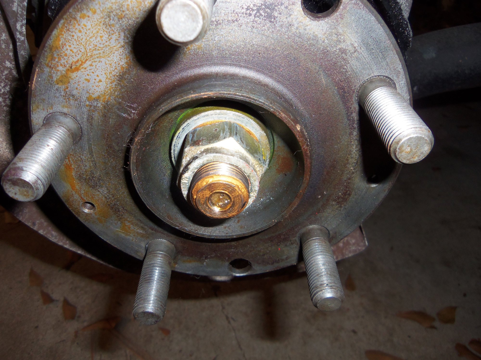
Mounting bolts were torqued to 60 ft/lbs. Outer hub lock nuts were only torqued to 300 ft/lbs. Why? That's all my 3/4" drive torque wrench would go to. I will see if Glenn has a stouter one I can borrow to get to the full 339 ft/lbs.
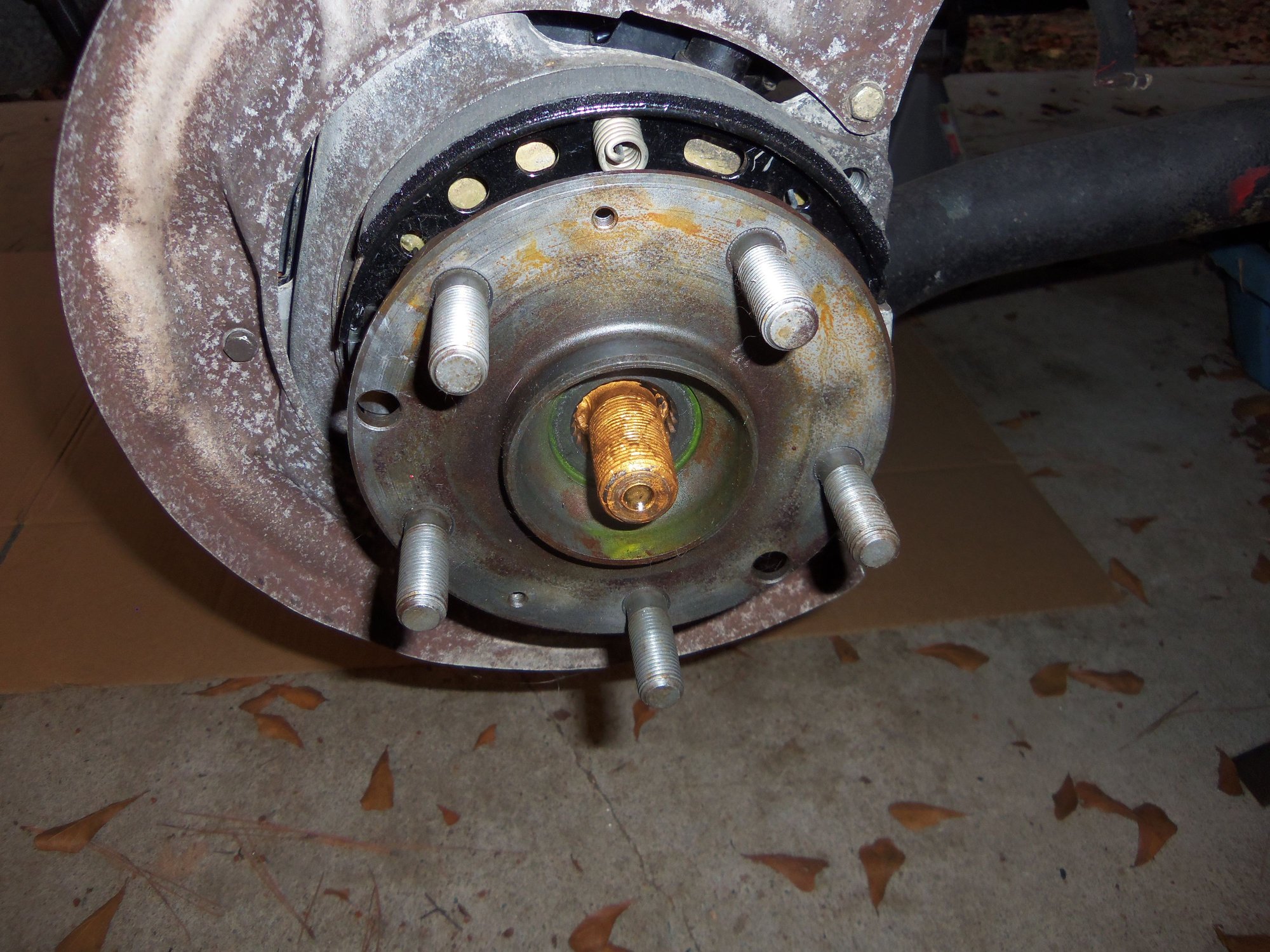
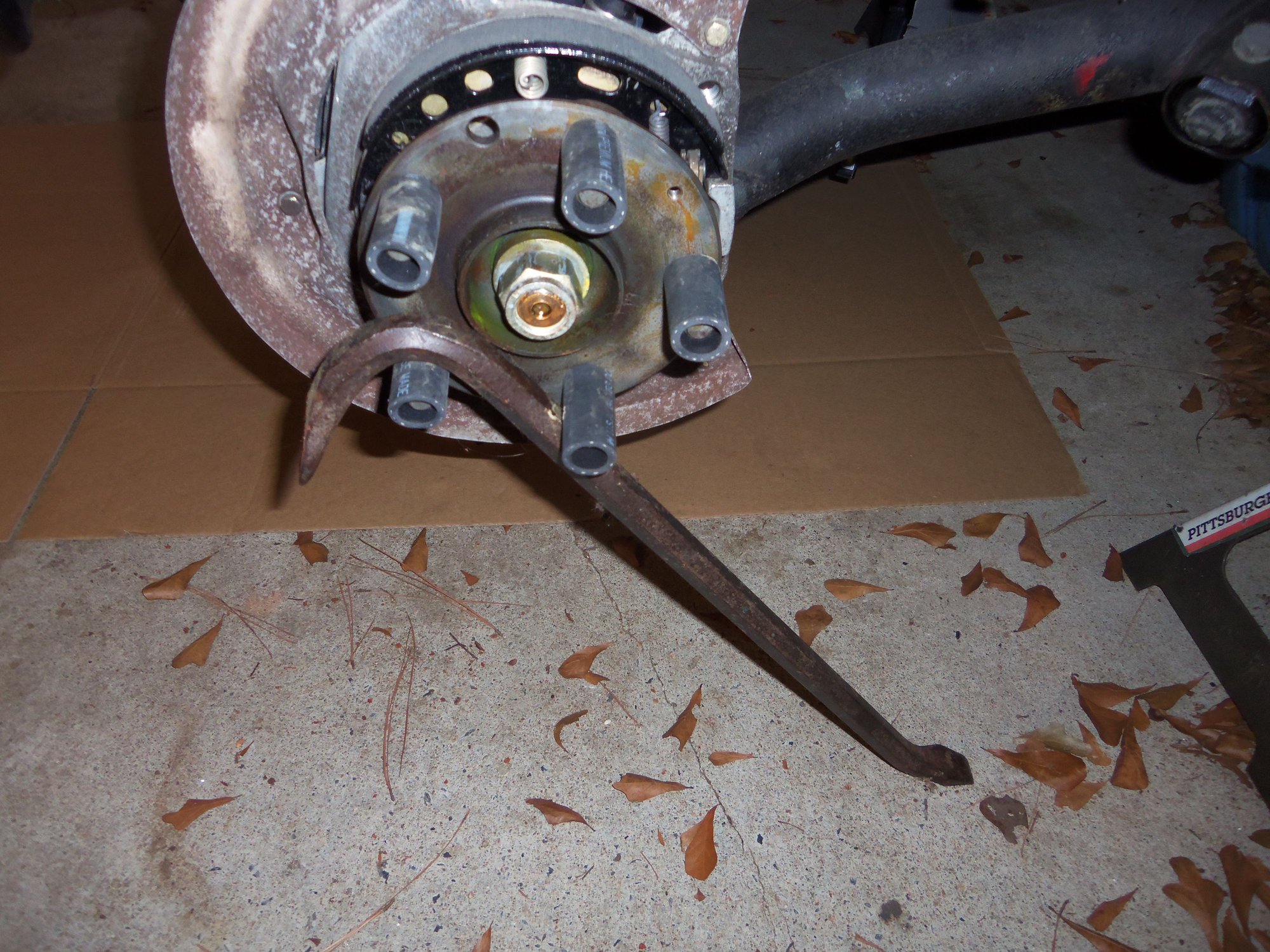
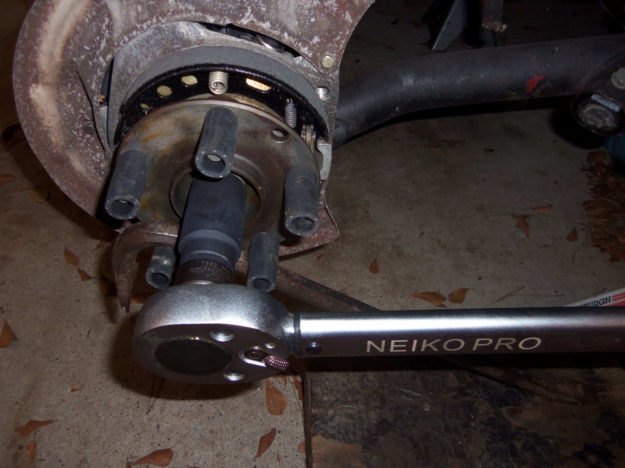
For tightening everything, I braced the hub with a pry bar on the lug studs. The lug studs had short lengths of 5/8" ID heater hose run over them to protect the threads. It looked clownish, but worked just fine.
Harder to line up than it looks.
Also no picnic to get lined up and the bolts started.
Ghetto, but it worked.
My He-Man 3/4" drive torque wrench was not quite He-Man enough...
Detail of ghetto brace and torque wrench.
Axle locknut torqued to 300 ft/lbs. Will find a He-Man'er torque wrench to get to 339 ft/lbs.
I did do a test on the outer CV joints. I had read a thread about a guy chasing vibrations in his shark. He and his mechanic threw everything including the kitchen sink at it. A NEW set of CV axles cured the vibration. Autopsy on the old ones involved cutting open the outer joints and finding significant wear in the ball races of the hubs. Clue for them was a 'bump' in the rotation of the outer CV joints while turning the shafts by hand.
So...I turned both my newly refurbished CV axles by hand and watched all four CV joints. I saw no unusual motion. So far so good...However, only road test will tell.
One more thing checked off the list!
The Red Witch has legs again...
As an aside, my hat goes off to all the guys who write epic posts. Dwayne, Rob Edwards, etc...
Not until I started really documenting the work I am doing on the Red Witch did I have a clue how much time it takes to post this work on Rennlist.
The above post on the CV axle refurbishment took over 4 hours to put together. From writing the text, to adding the photos, and then annotating the photos.
The work and the documentation are appreciated by all. Great effort, and thanks from me and i'm sure many others who read this.
dr bob
Thank you, dr bob!
I am trying to be useful with my threads and put out more DIY info for current and future 928'ers. To the point that I am going to try to start filling out the title blocks on my posts. It might make them more searchable. For example, my above post was about refurbishing CV axles, but is buried in my Torque Tube WYAIT thread.
We shall see how this works out.
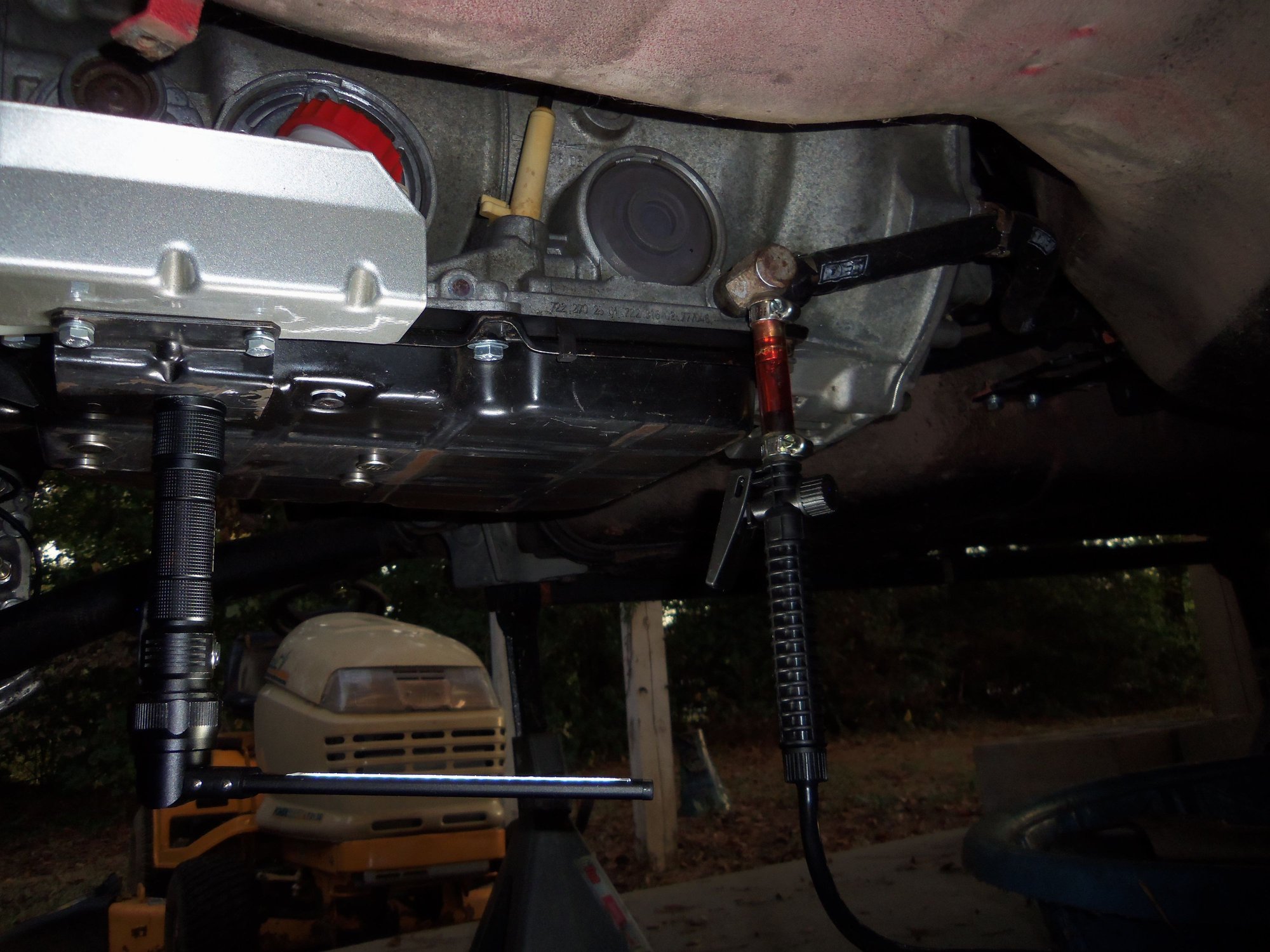
Add fluid to the A28.07 4spd automatic transmission.
Alright, I was wrong. There is one additional task I wanted to accomplish. I wanted to add some ATF to the A28.07 automatic transmission under the back of the Red Witch. Nothing more than peace of mind for me, really.
First order of business was to replace the crush ring on the drain plug in the pan. It was used and seeping. I removed and cleaned the plug, as well as the little bit of ATF residue on the pan around the drain.
Not wanting to waste the proper crush ring in the new transmission filter kit, I matched up the used crush ring with a copper crush washer from a kit I have. This is all relatively temporary, as I am changing the fluid and filter in 1000 miles of driving. Just because.
New copper crush ring was coated with pipe dope, then it and the plug were installed into the pan. Drain plug torque was 100 in/lbs.
Cleaned drain plug, used aluminum crush washer, new copper crush washer, pipe dope, and a torque wrench set to 100 in/lbs with a tight fitting 5mm hex bit.
Now for the fun part. A few years ago, I changed the transmission fluid on the Red Witch. I had a cute little hand pump that screws to the top of a quart bottle. I filled the transmission and torque converter by hand. All 13 quarts.
And then had to do it again when I had to work on the valve body.
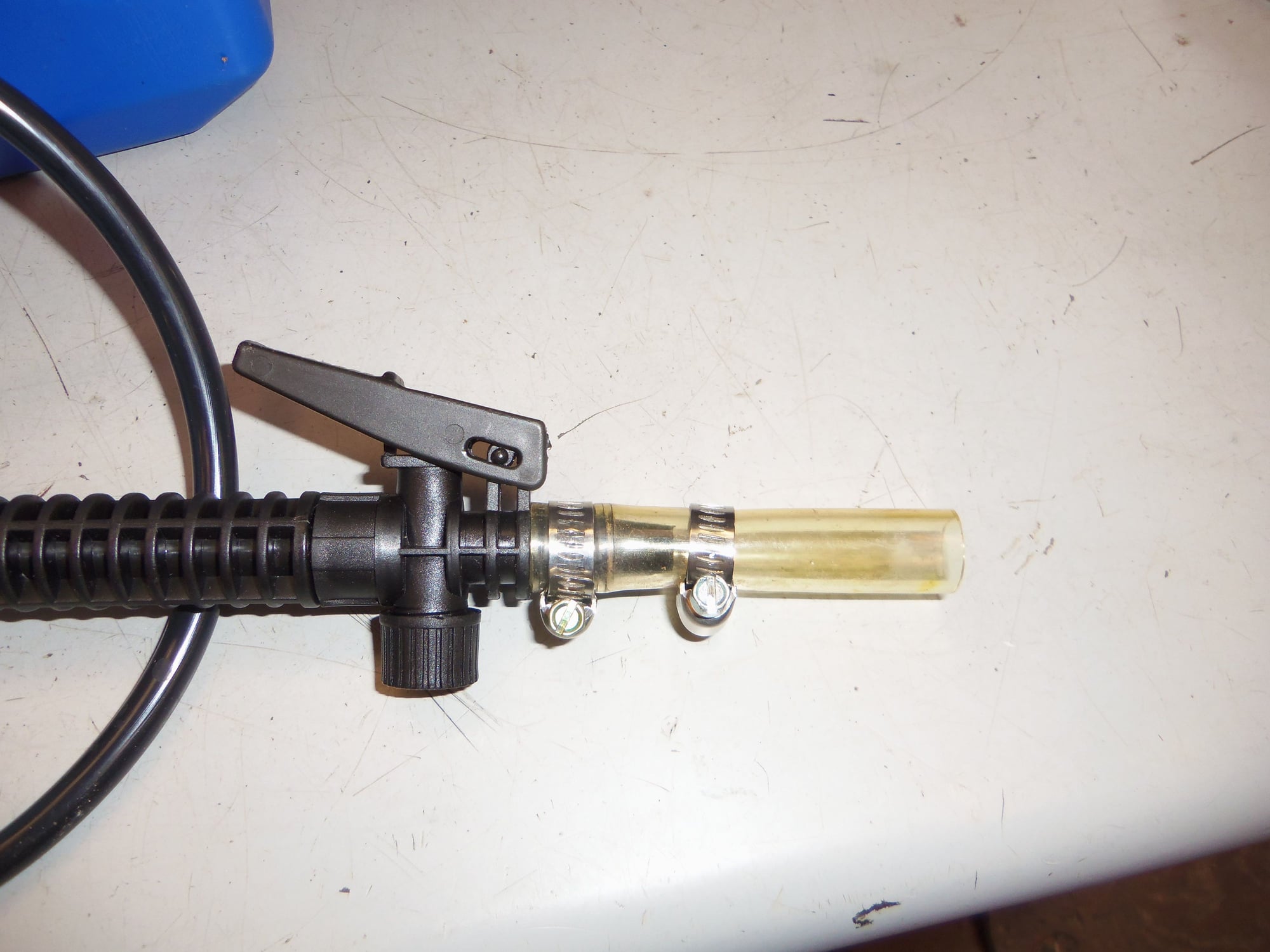
So...there had to be a better way. And there is. Taking a cue from Rennlist, I got a pressurized garden sprayer. I left off the wand and added a short length of tubing suitable for the fill connection on the later A28.** automatics.
I filled the sprayer with a gallon of SuperTech ATF, which is suitable for Dexron III applications. Yes, I know, Wal-Mart transmission fluid. Not the NAPA I normally run. Wal-mart AFT is good oil for this application. And, as I said above, it is all getting changed in 1000 miles. And I had this unused gallon left over from a fluid change that never happened on a family member's car because they blew the engine up.
Anyway, this gallon went in.
Short hose replaces wand and fits on fill port quick connect at the transmission.
I moved the garden sprayer under the back of the car and connected the nozzle to the transmission fill port. And then learned there is not enough room under the car to pump the handle to pressurize the sprayer. Cue moving the sprayer out from under the car, and awkward body contortions to pump the handle. Once pressurized, the sprayer filled the transmission pan up to the MAX level on the plastic reservoir in a relatively short time. MUCH better than the hand pump.
Sprayer nozzle hooked up to quick connect fill port on the transmission.


 09-12-2019, 10:15 PM