When you click on links to various merchants on this site and make a purchase, this can result in this site earning a commission. Affiliate programs and affiliations include, but are not limited to, the eBay Partner Network.
Thank you, SRaouf!
I had to use a spring compressor to disassemble the Boge shocks and Eibach springs from the donor 1988 S4 suspension and also for the original shocks/springs from the Red Witch.
My machinist has a wicked strong wall mounted spring compressor that I use.
Both rear Konis are set to 1/2 turn from full SOFT.
I did a bunch of searching on Rennlist 928 and found 1/2 turn from full SOFT to be a good starting point.
I will adjust as required after driving it.
I plan on setting the front Konis the same way.
Both rear Konis are set to 1/2 turn from full SOFT.
I did a bunch of searching on Rennlist 928 and found 1/2 turn from full SOFT to be a good starting point.
I will adjust as required after driving it.
I plan on setting the front Konis the same way.
I'm starting at 2 half turns all around. I like a firmer ride - sorely my my 86.5 with it's 89GT coilovers.
Nice work Seth your gonna have a new car when your done.
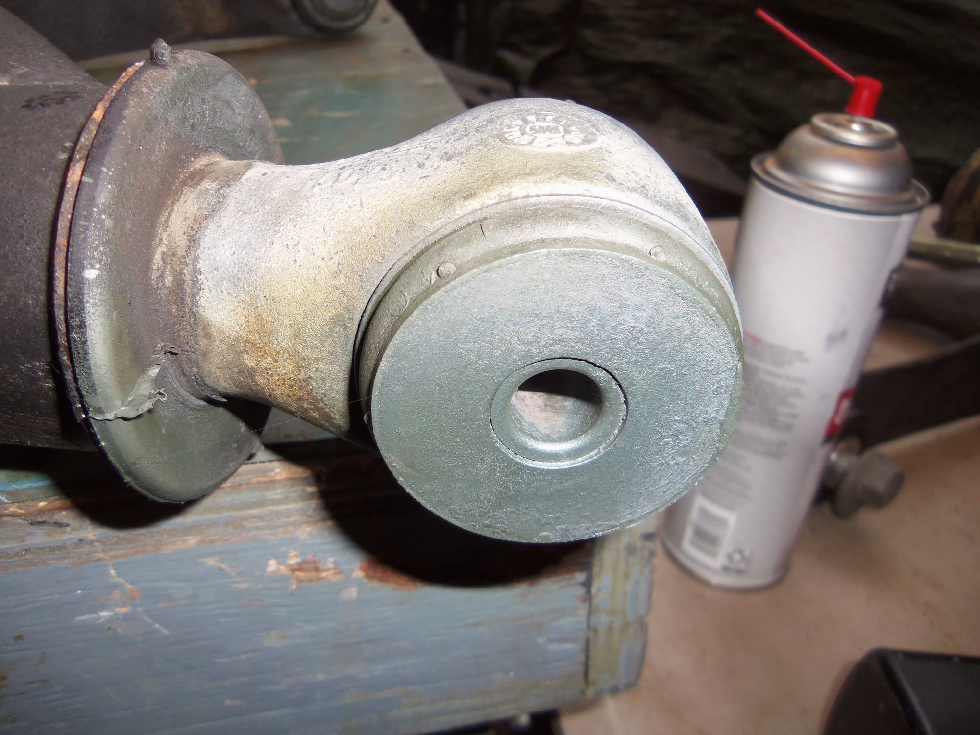
I was going to suggest that you get some stuff called fluid film ,
and spray it on any of the corroded bolt heads and clamps that are on the trans and TT and anywhere else .
this will act as sort of a cosmoline type coating but it wont hurt anything.
Farmers use it to spray outdoor machinery to protect it from the elements.
I have used it with good effect on my machines
This morning I was finally able to start reassembling the rear suspension on my Red Witch!
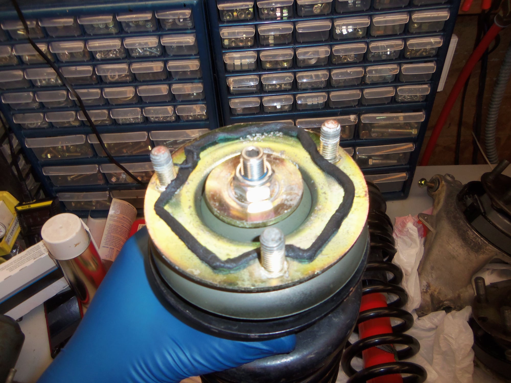
I started with the rear coilovers. Following Dwayne's advice, I put 3M strip putty on top of each shock mount for sealing. I am not sure if it was the heat or I am just incompetent, but I had a time of it getting each individual strip of putty out of the pack. A couple were sacrificed until I got the hang of it.
Looks easy to remove from the package. It was not.
Effective body seal for the top of the shock mount.
Being only me, I used a jack stand to hold each coilover in place once I had it aligned in the pocket. Top them off with the caps and new hardware, torque the locknuts to 33 ft/lbs, and call that part done.
Too tall jack stand holding coilover assembly in place by the lower spring perch.
Top mount studs lined up.
Cap and new hardware mounted.
Of course I didn't have the lower shock eye lined up right...
Things were going well. Which, long time readers will recognize, is why they went wrong...
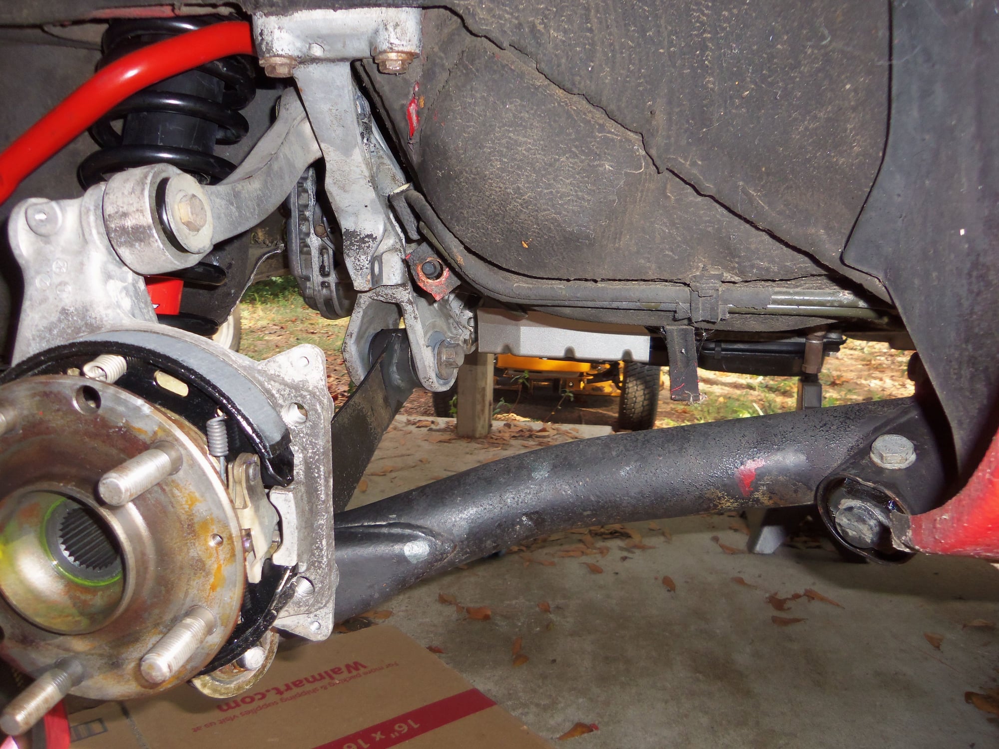
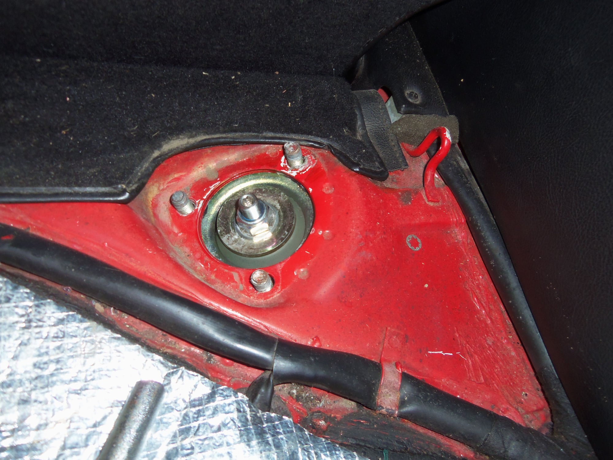
While under the car removing a jack stand, I noticed something. Specifically the conical depression on the rear suspension crossmember at that side for the upper control arm to mount to. There is a long bolt that holds the control arm to the crossmember. This bolt feeds in from the front of the crossmember and the head is captured in the casting.
Yeah...this part of the crossmember was up against the body in the rear seat area. There was NO way I would be able to start the bolt.
So...down came the rear crossmember. Again.
It was relatively quick. I supported the differential with a jack, removed the bolts for the crossmember, and lowered it on longer bolts from the rear antisway bar installation. I loosely installed both rear upper control arms then reinstalled the rear crossmember.
As far as my screw ups go, this one wasn't terrible.
Tapered receiver for the upper control arm.
Nowhere near enough room to get the bolt inserted between the body and the crossmember.
Bolt that is to go into the crossmember.
Differential supported, crossmember down.
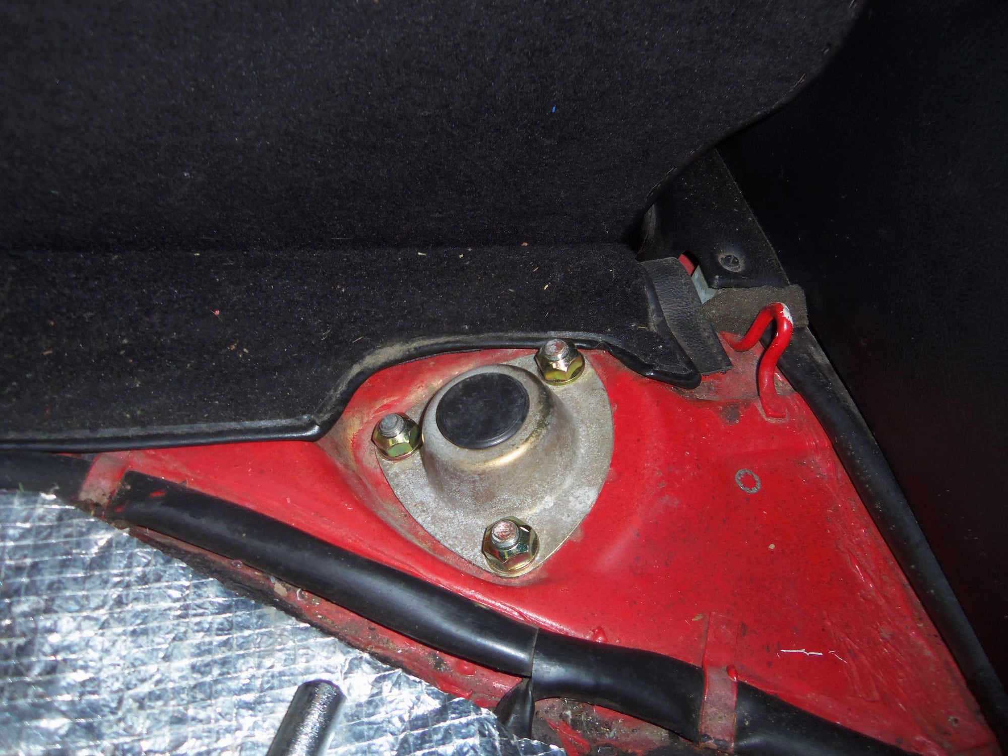
Moving on, I next installed the lower control arms.
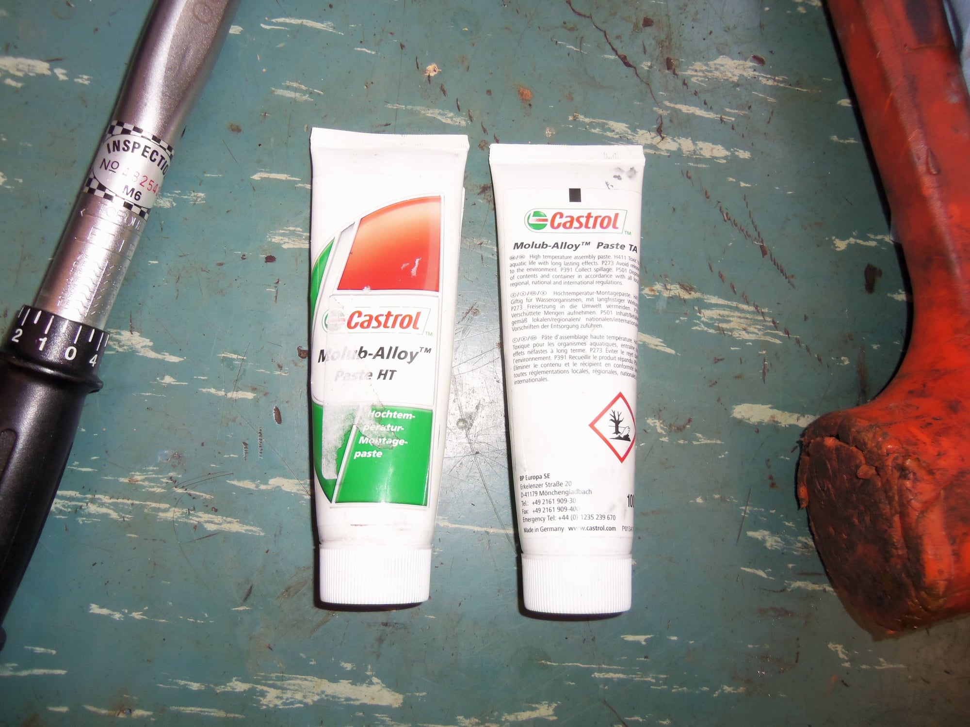
I had to stop and do a little prep work to the lower control arms. WSM calls for MolyKote U to be put on the bushings of the lower control arms. I broke out my can of Comet Torq-A-Verter moly dry lube again and sprayed the bushings. Not a professional job, but effective.
While waiting for the dry lube to...dry, I loosely installed the lower control arm front mounts to the body. Then, I installed the lower control arms into those mounts. It was a bit of a trick for my chunky fingers to manipulate the flat washer and new lock nut onto the end of the adjusting cam bolt shaft in the tiny pocket. Once I got that, it was just a matter of rotating the arm up to engage the camber adjust bushing at the end of the 'blade' into the mount at the bottom of the crossmember. The passenger's side required a slight tap with a mallet to seat. Installed the camber adjusting cam bolt and that was that.
Both lower control arms went in without much of a fuss, really.
WSM calls for this bushing to be coated.
This bushing as well.
Nothing said about this bushing, but I sprayed it anyway.
Passenger's side lower control arm installed via its bushings. Note how close the lower shock eye is to lining up with the control arm bushings!
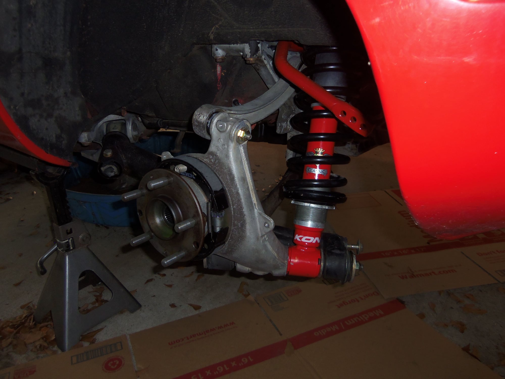
The shock shaft...now for the fun part.
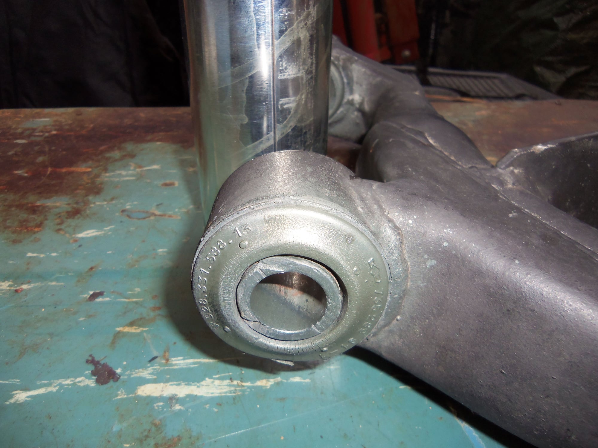
I had heard horror stories about installing the shock shaft. I was prepared to use a jack to push the shock eye into alignment. However, due to the Eibach springs being shorter, the shock eye lined up just fine. I started the shaft into the rear bushing on the lower control arm. I then used a mallet to push the shaft into the shock eye. Then pushed it back because I forgot to install the washer between the rear bushing and the shock eye.
I pushed the shaft into the shock eye until it was even with the front side. Now came the juggling act of the wheel hub carrier and the tapered spacers. Given advice is to hold the bushings in place with heavy grease or antiseize. Because I am me, I used antiseize, Optimoly TA. The back side spacer stayed just fine. Front side was a pain. Mainly because the bushing sleeves were JUST far enough to allow it all to slide in IF aligned perfectly. It took me awhile to get it aligned perfectly.
I did run into a problem on the passenger's side pushing the shaft through the front bushing on the lower control arm. The shaft was not aligned straight into the bushing. I am going to assume the rear bushing was a little out. Because I am a dumbass, of course I just hit the shaft with a mallet harder. And of course it didn't do anything. In my defense, I was not hitting on the new M14 locknut. I put one of the old lock nuts on for just this purpose. Anyway, I finally thought to go get a flathead screwdriver. Reaching through the front bushing sleeve, I was able to pry the end of the shaft into alignment, and then push it all the way through with the mallet.
Driver's side shaft went through with no problem.
Passenger's side shock shaft installed.
Last assembly step was to connect the upper control arms to the tops of the wheel hub carriers. Wham, bam, thank you ma'am, and done.
Upper control arm connected to the top of the wheel hub carrier.
I did have to look through past photos to make sure I had the cupped washer pointing the correct direction on the bolt head for the upper control arm.
NOTE: There was an expensive aspect to this evolution: Optimoly. I used a helluva lot of the HT and TA in assembling the suspension components! Any bolt shank that went through a bushing got HT. Anything that touched aluminum got TA. All four cam adjusting bolt shanks got slathered in HT. The bolts for the lower control arm front mounts to the body got slathered in HT. All the bushing sleeve ID's and faces got HT. Half of the shock shafts got HT, the other half got TA. All of the tapered spacers for the upper control arms and the wheel hub carriers got slathered in TA. As did the matching tapered receivers for the above spacers. The upper control arm holes and shock shaft holes in the wheel hub carriers got TA. All four mounting bolts for the upper control arms got slathered in TA.
As for the adjusting cam bolts...the cam faces got slathered in TA, as did the matching pockets in the crossmember and front mounts. Excessive? Maybe. Memory of seized bolts and ruined rear control arm rocker bars still fresh? YES!
Bottom line, I want this all to be no problem for my alignment guy to do his magic, and for it all to come apart with no problem for me in the future. To that extent, after the alignment is done, I am spraying all the exposed bolt heads, nuts, and threads with Fluid-Film. It will be ugly, but protected. There is precedent. The WSM calls for doing just that with a wax based coating. So I am good.
These two got quite a workout today...
Final step was to snug up all the various mounting bolts. I wanted to take out the play, but not tighten any of them. To my knowledge, all the suspension bolts are to be tightened with the car on the ground and the rear suspension loaded. So that is what I will do. All the through bolts were tightened until they could just be turned with a wrench. The shock shafts were tightened so that there was no lateral play in the wheel hub carriers, meaning the tapered spacers were tight.
Natch, I DID torque the lower control arm front mounts to the body to 33 ft/lbs.
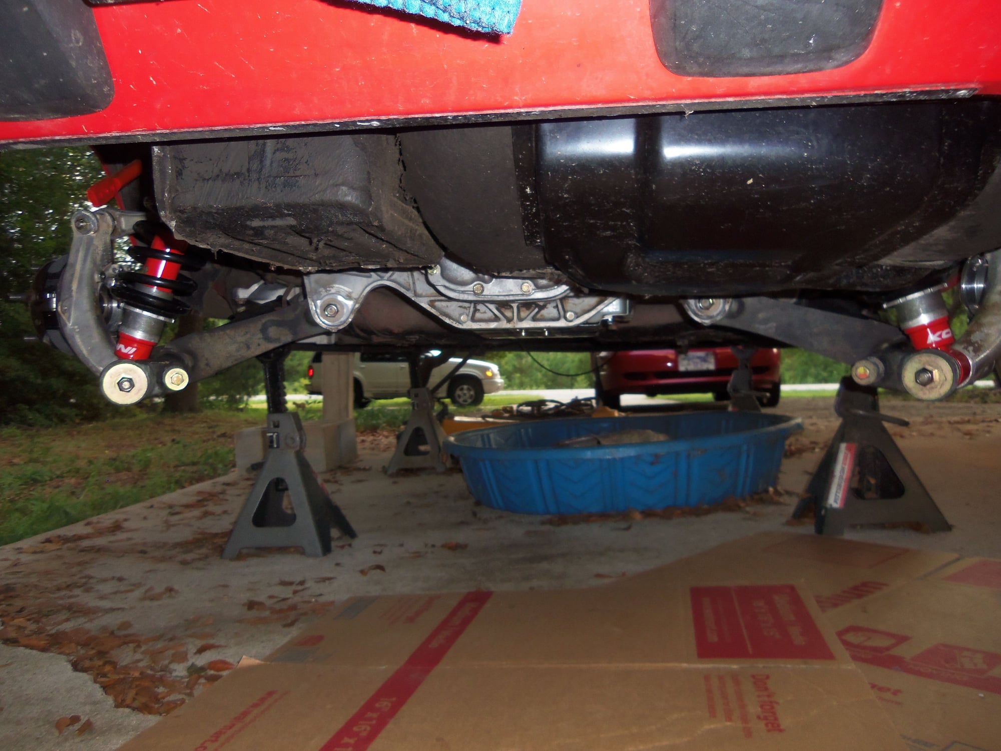
Passenger's side rear suspension.
Driver's side rear suspension.
Stan, I just read your reply. I am a BIG fan of Fluid film on my cars and trucks, as well as small engines. I will definitely be following your advice on this one!
Thanks!
I can now breathe a bit of a sigh of relief. Getting the rear suspension assembled and installed has been a big milestone for me.
However, there is much more to do to the rear suspension:
-backing plates
-parking brake cables and brackets
-resonator hanger brackets
-ABS wiring
Next big thing will be refurbishing the drive axles.
Next step is to find the box I have misplaced that has the good used backing plates I got from 928 International a couple of years ago.
Rear sway bar links, parking brake cables, and rear ABS wiring.
More incremental progress on the rear suspension of the Red Witch.
I have been side tracked a bit, had to replace a floor in a bathroom. Simple, you might say? Yes, for a carpenter. Which I am not...
Anyway, I have gotten some good work done at the back of the Red Witch.
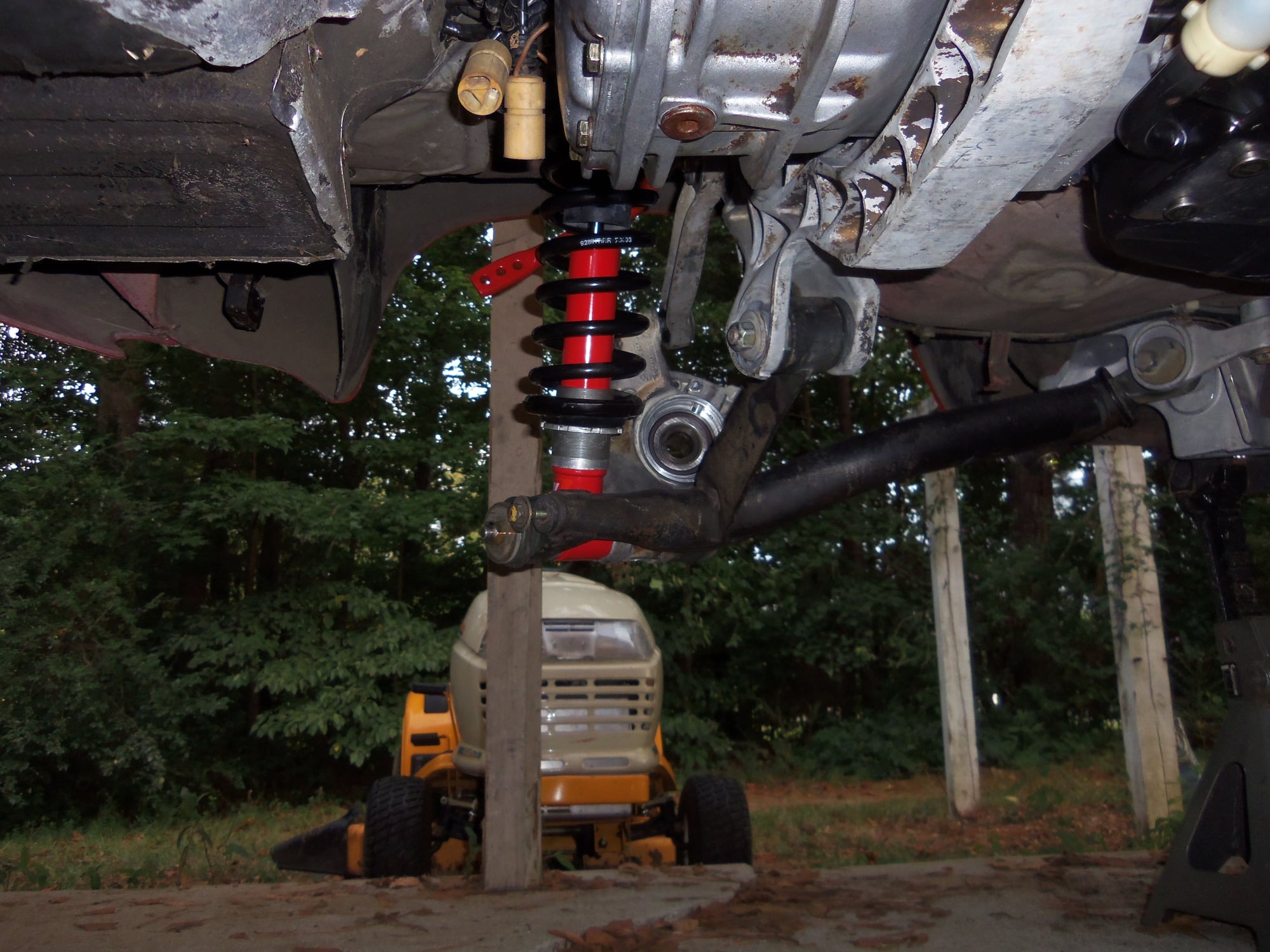
With the rear lower control arms installed, I could now install the adjustable rear sway bar drop links. I fogged the threaded rods with 2 coats of Rustoleum Satin Black for effect. Just me.
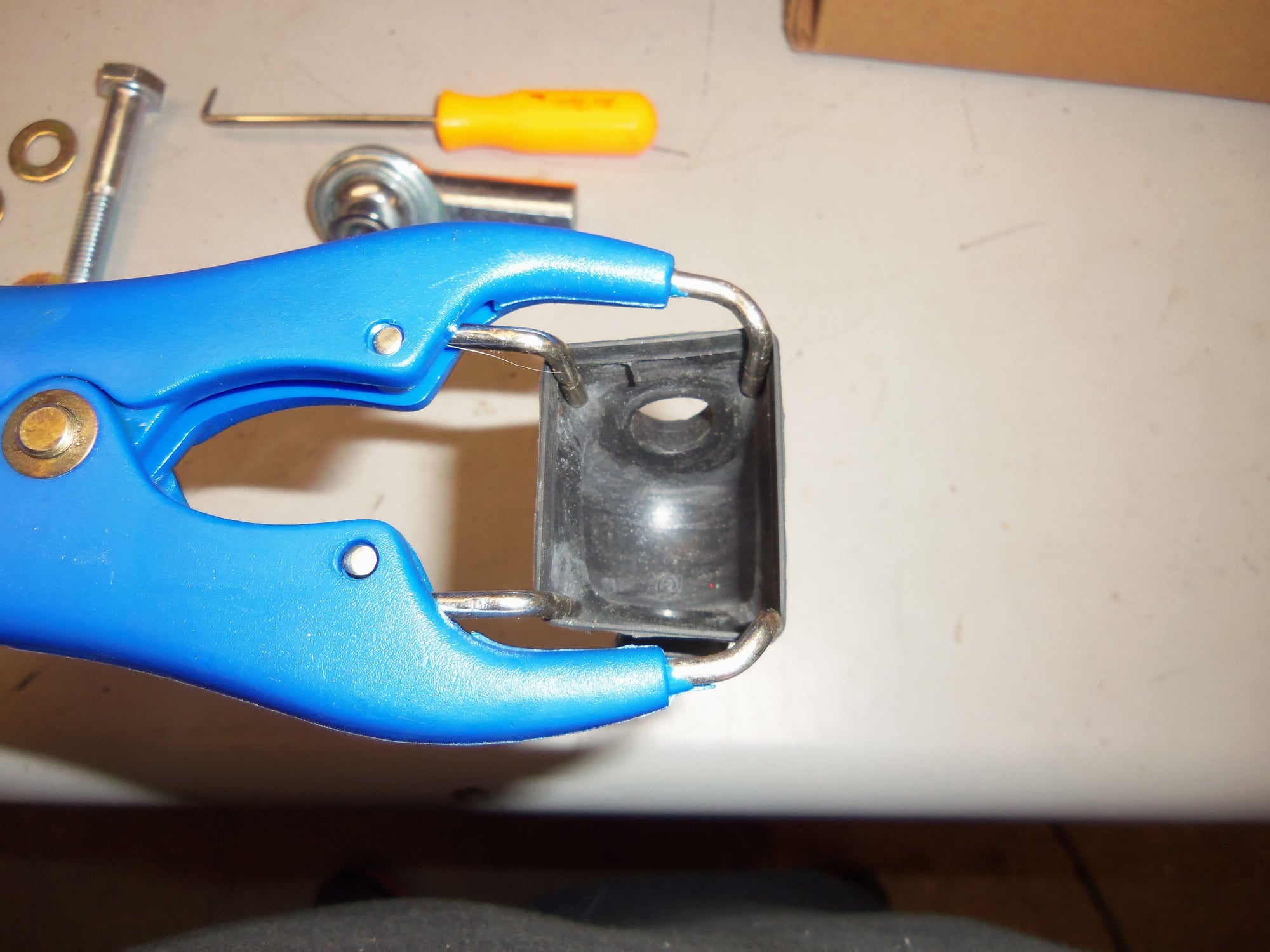
I have dealt with this type of rod end before, and have not been comfortable leaving them exposed to the elements. So, I ordered some rubber boots for them.
Good idea. Bad execution on my part. Mainly because the boots are a tad small.
The first test boot went on just fine. When I ordered the boots, I coughed up and bought the spreader tool for installing the boots. Very good idea, as I saw no other way to open the boots to get the rod end in.
Emboldened by this success, I forged on. Long time readers should see this blatant death flag waving now...
To make installation a little easier, I sprayed the insides of the boots with silicone spray. As well, to lubricate the rod ends, I dribbled a little gear oil on the *****.
Terrible, terrible idea.
The lubrication prevented the spreading tool from maintaining any kind of grip on the insides of the boots to get the rod end in.
I tried cleaning the boots with brake cleaner, wiping the excess gear oil off the rod ends, too bad. Nothing worked.
I stared at it and kept trying over and over. And kept failing over and over.
Finally, in desperation, I bent the tips of the spreader tool to grip the insides of the boots a little more aggressively.
That worked! I was able to get all four lubricated rod ends into all four boots.
I lubricated the ends of the threaded rods with Optimoly HT where the rod ends would thread on. My original intent was to adjust the rod ends to match the length of the original OEM drop links. Nope. With the rod ends screwed on as tight as I could get them, the adjustable drop links were still a bit longer than the OEM drop links. Eh, OK. For now I make both adjustable drop links the same length. I will adjust them as per the instructions for the rear anti-sway bar when the rear wheels are back on the ground.
I installed both adjustable drop links, but did not fully tighten the mounting hardware. Mainly because of the boots. The edges of the boots were a little finicky to keep on the bosses of the red end ***** and not fall down to get trapped against the sway bar or control arm. Once the car is back on the ground and rear suspension is loaded, I will tighten the mounting hardware.
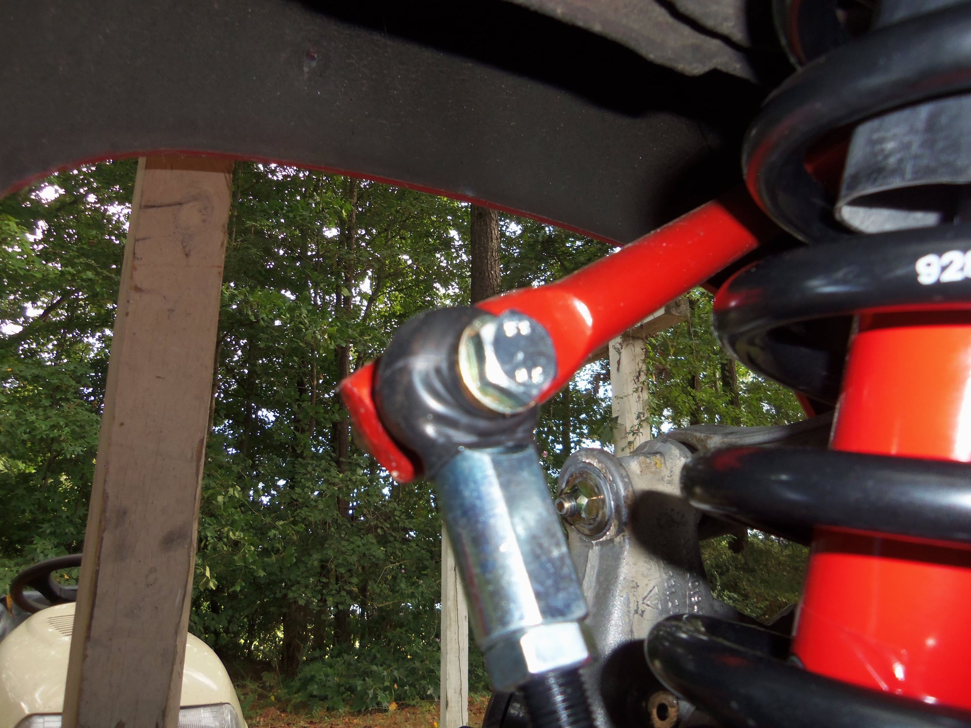
Painted threaded rod, rod ends, boots, and upper mounting hardware. Note one rod end and boot are mocked up.
Boot installed over rod end.
Boot opening pulled over boss on rod end.
Boot and spreader installation tool.
Inserting tool into boot.
Spreading boot.
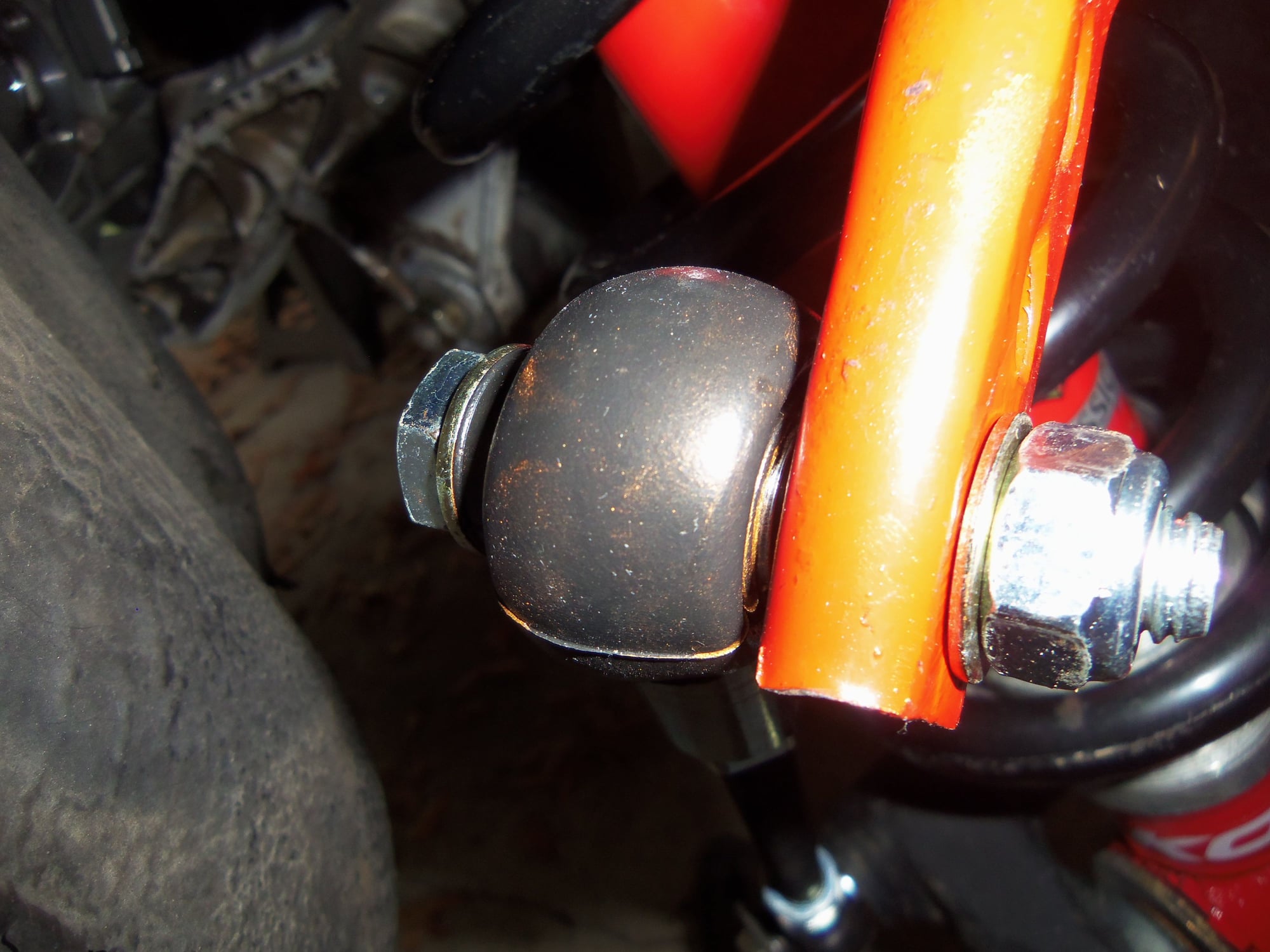
Completed adjustable rear drop links compared to OEM drop link.
Also, I went back and tightened the rear upper shock nuts with a 'through' ratchet. Worked a treat.
Holding shock rod with 6mm hex bit socket and top ratchet, tightening shock rod nut with 'through' ratchet at bottom. Worked well.
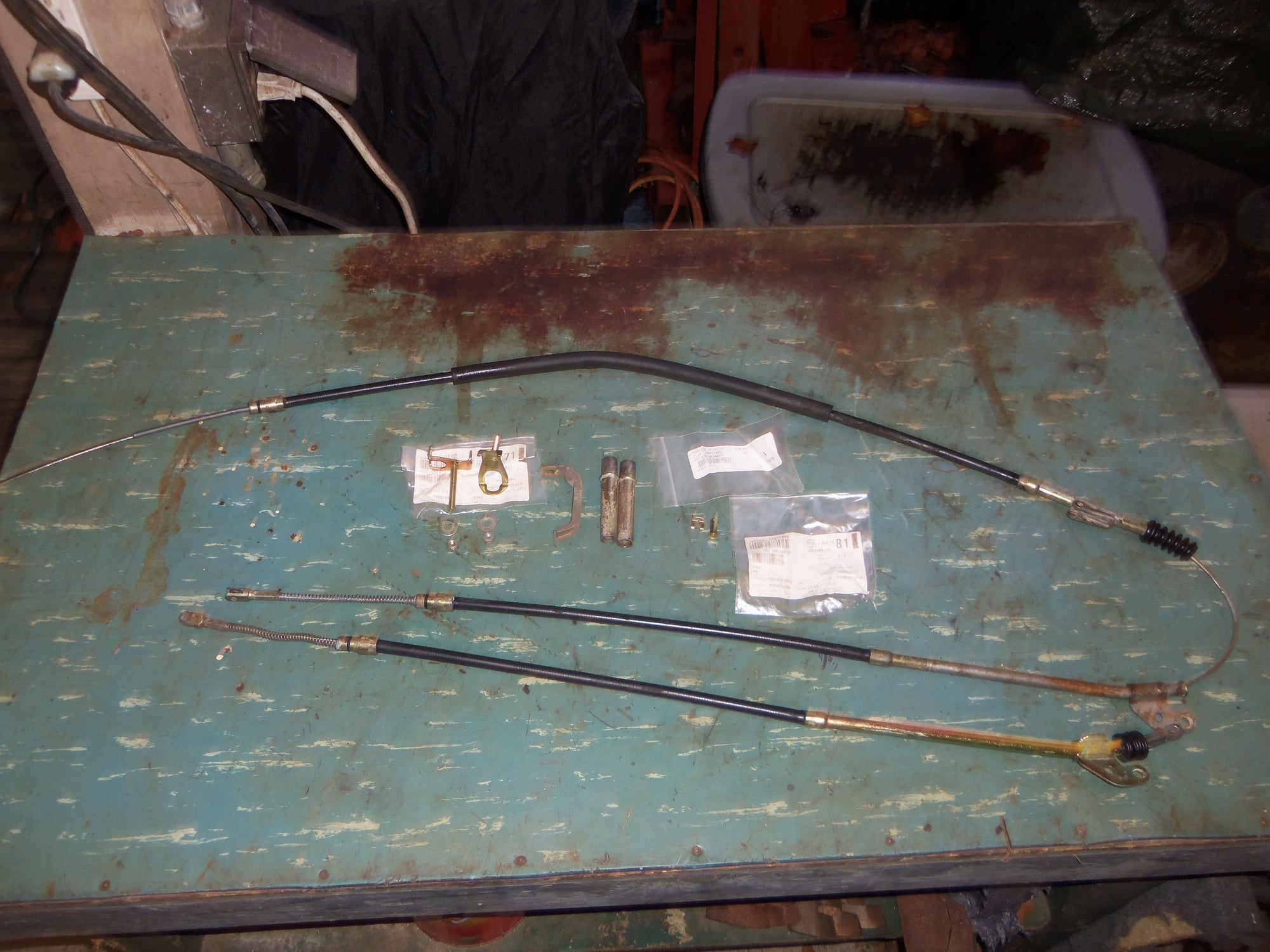
Onto the really fun part...parking brake cables!
The OEM parking brake cables that came on the Red Witch were serviceable, but ratty. I wire wheeled the rust from the metal casings and then fogged them with Rustoleum a few years ago. A couple of years ago, I bought a used set of parking brake cables from 928 International. Last year, a semi-complete set of parking brake cables came with the donor 1988 S4 rear suspension. Unfortunately, I could not use the main cable. It had been cut out of the car. (ANGRY FACE)
I mixed and matched all the cables I had and came up with a decent set. The inner vinyl sheathing for the metal cables is trash on all of them. No way around that. The rubber bellows boots are serviceable. I sprayed aerosol white lithium grease into the cable housing ends and on any exposed cable as best as I could. All the cables pulled smoothly with no catching or dragging.
If my put together cable set becomes too problematic, I may cough up and buy a new set. Only $350 for a set...
I had a mix of new and good used hardware to go with my mix & match cable set.
Everything went together RELATIVELY easily, all things considered.
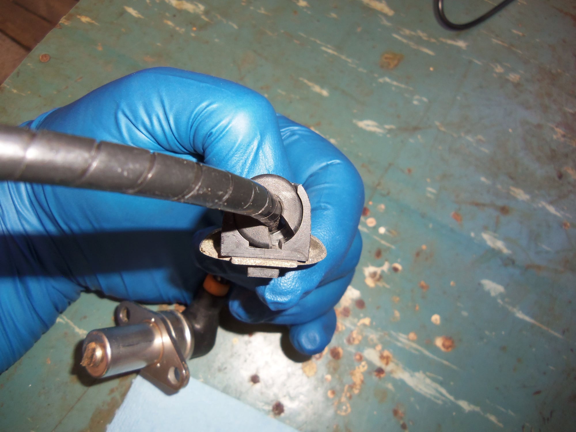
I lubricated the ends of the parking brake cable tubes to the rear wheel bearing carriers with Optimoly HT. I went with HT instead of TA because there looked to be steel sleeves pressed into the aluminum rear wheel bearing carriers. So, I was putting a steel tube into a steel sleeve. Hence, HT.
I lubricated all three cable end O-rings and fittings with Dow Corning 111. Seemed like a good idea due to the O-rings, and I put enough on that it should prevent water ingress. And rust.
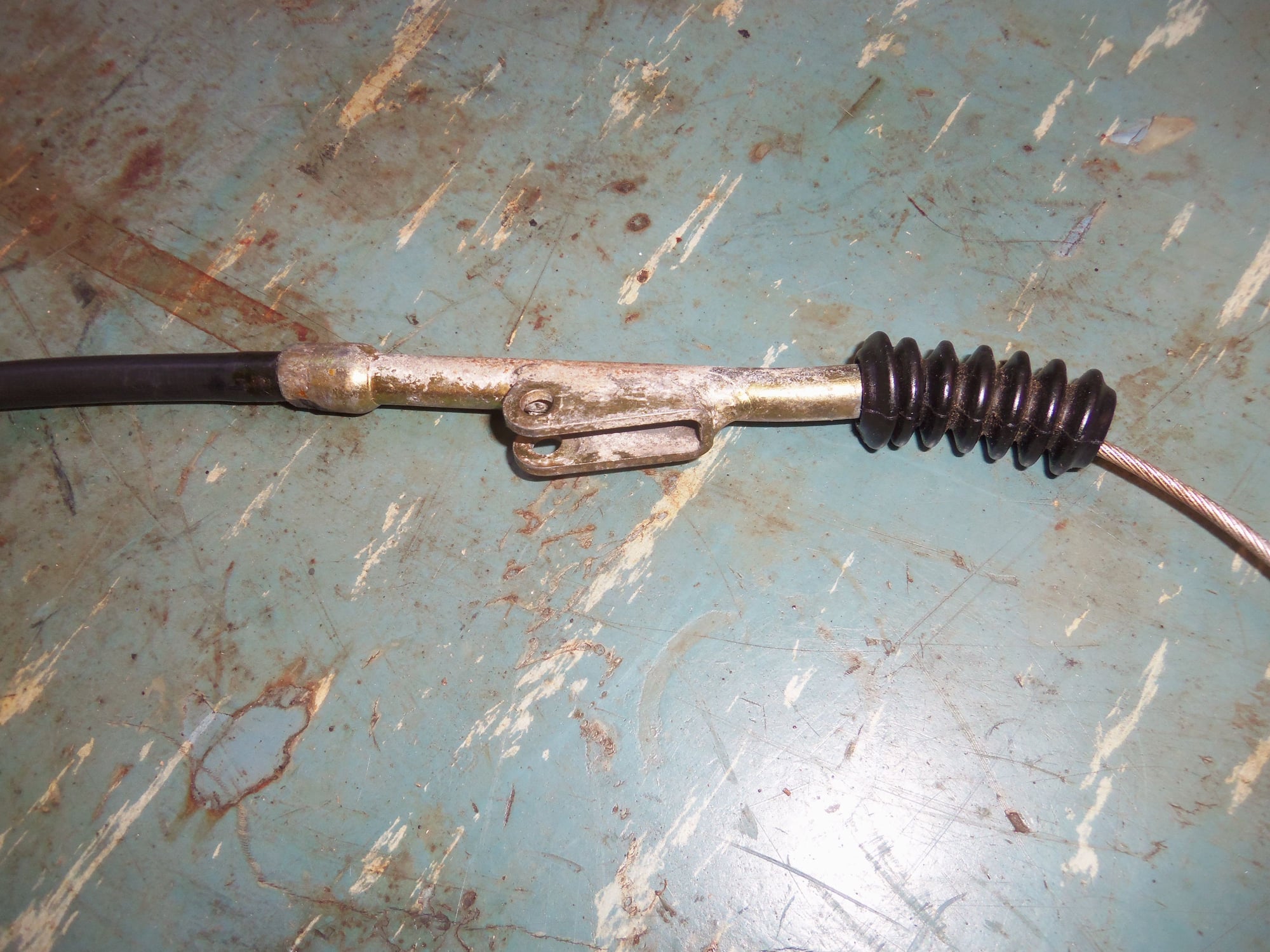
My concerns for getting the cable end yokes into the parking brake shoe actuators were unfounded. I just pried up on the top shoe with a large screwdriver and pulled the actuator right out. Assembled the actuator with the cable end yoke and then reinstalled the actuator back into the parking brake shoes. Was pretty easy.
Which is good, because I had to do it twice. I had the parking brake to rear suspension crossmember holding brackets oriented backwards. Had to disconnect the cable end yokes from the actuators to get the brackets off and turned around. Minor pisser...
I lubricated the threaded end of the main cable with Optimoly HT before I installed it into the adjusting yoke on the parking brake handle inside the car. I put SOME tension on the parking brake cables, but will do final tensioning when the rear disc rotors are installed. I did work the parking brake handle several times to watch the shoes expand. Just because.
I did note that I may have to unbolt the middle lower mounts for the parking brake cables later. The cables are blocking the transmission mount to crossmember bolts that I need to tighten later. No big deal.
Mix & match parking brake cable set, mix of new and good used hardware.
Cable ends.
Mid point junction and bellows.
Other side of mid point junction.
New cable securing brackets, new locking pin and clip, used tubes and bracket.
Main cable routed into the body.
Passenger's side cable end installed in actuator.
Passenger's side cable installed into tube installed into rear wheel bearing carrier.
Passenger's side cable clamp. This is one of the clamps I initially installed backwards.
Midpoint junction and mounting.
Driver's side cable clamp and bracket for main cable.
Driver's side cable installed into tube installed into rear wheel bearing carrier.
Driver's side cable end installed into actuator.
Last thing to do was ABS wiring.
One of the first pushes down the WYAIT slide was the driver's side rear ABS sensor back in July of 2016. I ruined the sensor removing it from the wheel bearing carrier. Too much violence on my part. $100 to 928 International and I had another sensor. This sensor still had a good jacket on its wiring, as opposed to the good sensor from the passenger's side wheel bearing carrier.
I cleaned both sensors up. I removed all of the old damaged jacket from the OEM sensor then laboriously wrapped the wires in silicone self fusing tape. Then I wrapped that in spiral wrap. Spiral wrap as well for the 928 International sensor.
The brake wear sensors and cables were in excellent condition. I just cleaned them.
Later that year, I removed the driver's and passenger's side rear ABS body harnesses and did the same cleaning/wrapping to them. The harnesses were good, but the jackets and grommets were garbage. As are all of this vintage. I am aware that there are new harnesses and grommets available, as are new grommets. Since my harnesses are serviceable, I am running them for now. When I drove the Red Witch, she had no ABS faults.
On a side note, the donor 1988 S4 rear suspension had two ABS speed sensors in good condition. I have them as spares, though they need to be cleaned and wrapped.
As the Red Witch did not come with rear disc brake dust shields when I got her, I bought a set of used ones from...you guessed it, 928 International. The donor 1988 S4 suspension did have dust shields, but they were mangled beyond use. I did salvage the better condition mounting hardware, and the ABS wiring junction brackets.
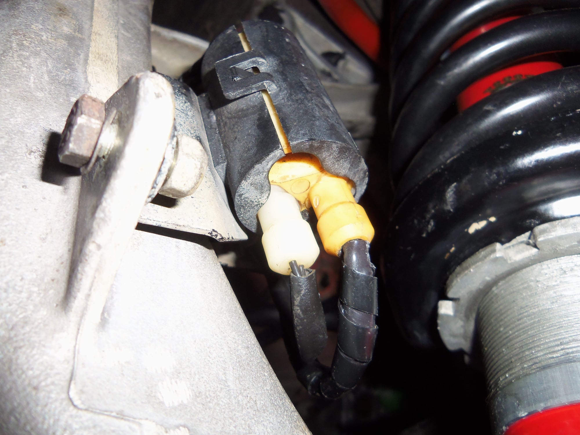
According to WSM Volume 4, Section 45, page 45-11, the ABS speed sensors and the bores in the rear wheel bearing carriers are to be coated with Molykote Longterm 2. Once again down the rabbit hole of google. Once again no readily available small volume source. Reading up on uses of Molykote Longterm 2 for ABS sensors, I saw a few posts recommending CV joint grease. Done. I have plenty of that on hand.
So, both sensors and bores were coated with CV joint grease, as well as the new O-rings that go over the sensors. I installed the sensors and used a little medium strength loctite on the mounting bolts. Because.
Next I installed the ABS wiring junction brackets on both rear wheel bearing carriers. I did NOT install the dust shields at this time, because they would block my view of routing the ABS wiring.
With the sensors and brackets installed, it was then just a matter of routing the body harnesses to the brackets and routing the sensor wires to the brackets. There are many twists and turns for the body harnesses at the brackets. I stared at the photos on WSM Volume 4, Section 45, page 45-12 several times until I got it right in my head. It took me a couple of times to get the barrel connectors correctly seated and oriented into the black clamshell clamps.
On that note, I have a bag full of new black clamshell clamps for the ABS barrel connectors, and the plastic receivers for the grommets. However, the ones that came on the donor 1988 S4 rear suspension were in excellent condition, so I reused them. I will save the new clamps for the front ABS wiring.
As for the grommets...I went ghetto. I should be ashamed, but I am not. I cut and fit simple grommets to go around the ABS wiring, and then push into the black plastic grommet receivers. The grommets are tight in the receivers and I am OK with it.
The used dust shields were ugly and did not clean up well. However, I am glad to have them. On they went.
Passenger's side rear ABS speed sensor. Shredded outer jacket.
However, the barrel of the sensor was pristine. Ignore the corrugated conduit on the cable. Failed early attempt.
Driver's side ABS speed sensor. Note the corrosion on the sensor barrel.
Driver's side sensor. Note the bent ear and the damaged barrel. I did most of that...
Used sensor from 928 Intl at top, good sensor from passenger's side at bottom. Both cleaned and ready to be wrapped.
Both sensors wrapped.
Rear ABS body wiring harnesses. Shredded outer jackets have been removed.
Dow 111 for a light coat on the seals for the sensor plugs, medium strength loctite for the sensor mounting bolts, CV joint grease for the sensor barrels, and the ghetto grommets.
Mounting of the grommets in the plastic receivers.
1986 rear ABS wiring at wheel bearing carrier. Photo from WSM Volume 4, Section 45, page 45-12.
Passenger's side speed sensor mounted.
Passenger's side speed sensor and brake wear sensor plugs into rear body harness barrel connector.
Passenger's side rear body harness barrel connector.
Routing of ABS wiring on back side of passenger's side rear wheel bearing carrier.
Rear body harness from passenger's side wheel bearing carrier to the bracket on the crossmember.
Rear body harness up under the passenger's side of the body, going up into the rear hatch area.
Driver's side speed sensor mounted.
Driver's side speed sensor and brake wear sensor plugs into rear body harness barrel connector.
Driver's side rear body harness barrel connector.
Routing of ABS wiring on back side of driver's side rear wheel bearing carrier.
Rear body harness from driver's side wheel bearing carrier to the bracket on the crossmember.
Rear body harness up under the driver's side of the body, going up into the rear hatch area.
Passenger's side dust shield installed.
Driver's side dust shield installed
So, at this point, the rear suspension is pretty much done. Finally.
All that remains is to clean, inspect, lubricate, and reseal the CV axles from the donor 1988 S4 rear suspension.
I hope to be able to do that this weekend.
However, the Explorer is due for some pre-FRENZY road trip maintenance...
Thank you, Kevin!
Step by step, one piece at a time.
Thank you, Curt!
I am taking this as high praise, as I hope you intended.
However, all is not as it seems. My outside work bench cover is nothing so plebeian as vinyl flooring.
That is GEN-YOO-WHINE milspec insulated switchboard matting, removed from Nr. 3 Switchboard Room aboard the USS Cape St. George, CG-71, during a yard period in 1998.
It has stood up quite well to the abuse I have heaped upon it.
Now, having said that, this matting is now unobtainium for me. I am open to suggestions for a good, durable replacement.
And, for the sake of friendship, I will cheerfully accept your gift of a piece of new vinyl flooring at FRENZY!

 08-10-2019, 02:34 AM


")