When you click on links to various merchants on this site and make a purchase, this can result in this site earning a commission. Affiliate programs and affiliations include, but are not limited to, the eBay Partner Network.
I got my injectors based on impedance (high Z, no resistor packs or peak & hold board needed) and the price was right. They aren't so big that idle quality is compromised. I would have reused my stock injectors but they looked like they were salvaged from the wreck of the titanic and were really noisy.
My low load cells are probably rich, because I usually enter fuel cut (triggered at 0% TPS and high vacuum) so I never tried too hard on tuning them.
you sure about this?
or are there 2 "squirts" per 720 cycle, fired in batch mode?
that would change the calculator's result to 8.3ms
Originally Posted by odonnell
Are you still running 55# injectors? 13 ms is waaay too high. At 2.5 bar fuel pressure, I'm getting ~7.8 ms and at 3 bar, about ~7.2 ms. There's a calculator about halfway down this page: http://www.megamanual.com/v22manual/mfuel.htm
My only comment would be about the fuel pressure you're getting 24# at. According to clark's garage the stock injectors are about 22.5# at 3 bar (which is the pressure that most tuning software assumes, you adjust your req_fuel based on your actual FPR). For a 2.5 bar FPR, I calculate 20.7 lb/hr.
With regard to the value being cut in half
For batch fire, you have 1 squirt per cycle. It just injects that cycle's worth of fuel at once. You would only halve the value if you were on semi-sequential, which breaks up the fuel into 2 shorter bursts. There are a few posts Doug and I made a few pages back with detailed tech info, but basically, you'll use 1 squirt per cycle for batch fire.
In reality req_fuel is only marginally important to have set correctly. Your VE table and fuel trims (warm up, accel enrichment, corrections, etc) are multiplying this value. Even if it's wrong, your experimentally-found curves will compensate and you'll end up with the right AFRs everywhere at some point. But it's much more sane to have it set as close as you can. Another important parameter is dead time....that's added, not multiplied, to your injector open time so it'll really affect low RPM fuel accuracy.
I had just assumed the injectors were 24# or so.
Thanks for the 1-squirt confirmation.
In that case...
hey guys, I am interested in mega squirting my 1983 944, but am confused as to how to mount a trigger wheel on to my crank pulley. is there a special one for the N/a 944's? do I need a different pulley?? any help would be greatly appreciated
thanks for the links, but im still confused as one of the trigger wheels is for their pulley, and the other bolts directly to a 944 turbo pulley, so would i need to get their special pulley in order to use a trigger wheel on my N/a? after looking at your build threaad, it looks at first glance like you just used the stock pulley and put the wheel behind it, does that mess up the spacing with the belt or anything?
I used the 6" wheel, the turbo crank pulley is the same as the NA. You have to get longer bolts to compensate for the added thickness, Im pretty sure I documented that somewhere in that thread. I was also concerned about belt alignment but it was negligible. I've been running that setup for a year with no issues, a few millimeters doesn't make a difference.
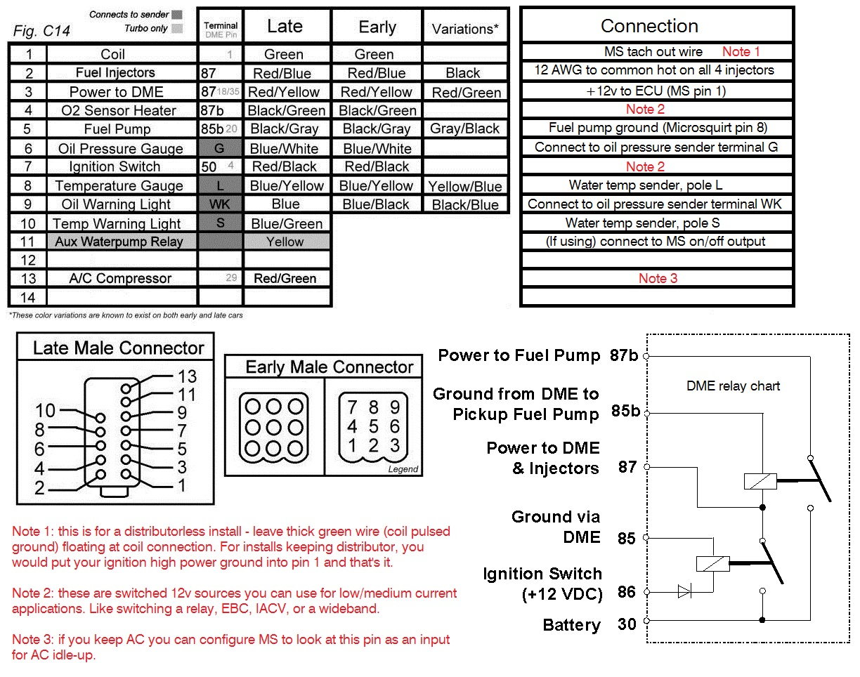
I was talking to Doug about this earlier and wanted to share a summary of how to wire to interface a custom ECU harness to the body harness (which connects to the fuse/relay panel).
The easiest solution is to cut the connector off of a donor DME harness, and attach these wires to the cut off side:
For the wires going from the water temp and oil pressure senders, just use some ~18 AWG wire to complete the connection, crimping on spade or eye connectors as appropriate.
Thanks for posting this Michael. Would you mind clarifying terminal S and L on the water temp sender (Note: The wiring would be slightly different if you use an early single pole temp sender since on the late cars, one pole is for the temp gauge and the other is for the warning light; while those functions are integrated into one pole on the early cars) and the G and WK poles on the oil pressure sender? I understand how they're supposed to be wired up, my question is more where you got the names of those poles from.
Actually I'm curious Michael since you have an early car, how did you wire up your temp sender?
Just now seeing this. Being that I have an early car, I ran a wire from pin 8 on the connector right to the sender pole and crimped on a spade connection. Couldn't be easier.
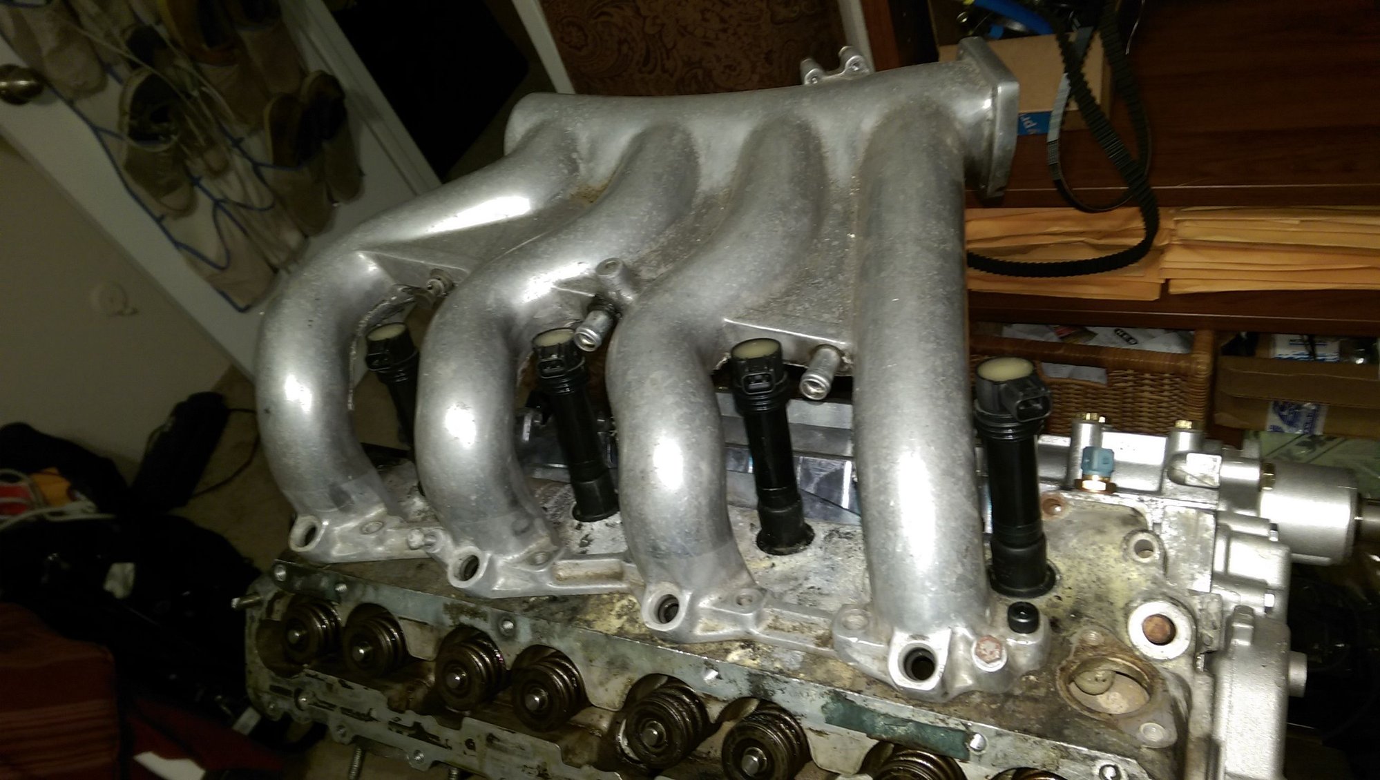
Is anyone running Coil On Plug ignition? I've got some Cayenne V8 and VAG 1.8T COPs I would like to use on my 944S2 motor but finding information on things like dwell time is proving difficult.
Dwell will depend on the coils you run, 1.8-3.5ms is average for what I see for stick coils (the ones shown above are modified Hayabusa coils that like ~2ms).
Once they're wired up, go into test mode in Tuner Studio and set the dwell to something like 2ms and see what sort of sparks you're getting. The real test is with the engine running. Increase dwell 0.1ms at a time until they start to feel a little warm, then back it down a little. The "correct" way is to use an O scope but this is what I've done with success.
I'm working night shift this week, and it's really slow...so, I wanted to share a solution to an issue that I know both Doug and myself have had with our MS installs:
Wideband calibration correction
Installing a wideband and plugging it into the correct MS input pin is straightforward, and so is setting it up in TunerStudio. If you aren't sure how to do this, you need to find the voltage/AFR curve in your wideband owner's manual, and find the respective setup section in the MegaManual for your specific ECU.
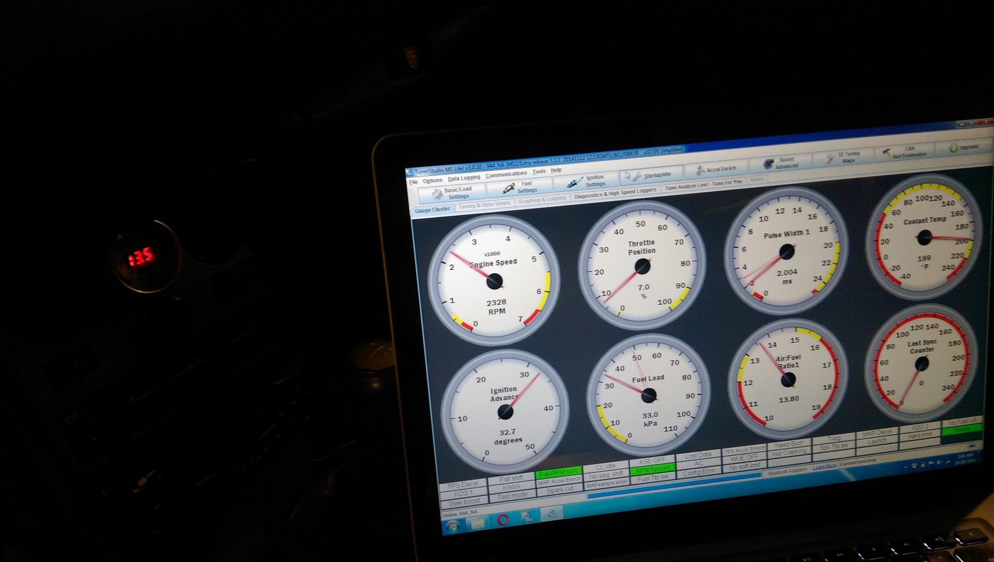
With the car running and TunerStudio open, you should see 2 AFR readings... 1 on the gauge itself, and 1 in TunerStudio. The former represents what the wideband controller is sensing, and the latter represents what MS is actually seeing from the signal wire. With any luck, they'll match, but in many cases there is a small error. In my NA, it was about 0.3 across the board.
So, is the error large enough to warrant further action? Probably so if you are using Auto Tune or any sort of closed-loop EGO correction. Otherwise, your ECU will be modifying the fuel table to meet AFR targets that are richer or leaner than what the engine is actually getting. In my case, 0.3 AFR is enough to bother. In a turbo car you definitely want to make sure your fuel trim is solid.
Step 1 is to collect some data.
Approach #1
If you look at the URL above, the author discusses how some widebands have a controlled warmup where they show 1/3 max lambda for the first 5 seconds and 2/3 lambda for the next 5 seconds. Those give you 2 data points each which is enough to make your correction.
The strategy would be to wait until the car is fully at ambient temp, connect your laptop, and key on without cranking the engine. The wideband and MS should be getting power. Because the readings are steady for 5 seconds each, you have time to write down the 4 data points...what the gauge says, and what MS says at each stage.
Approach #2
This is a more general approach that does the same thing. The reason approach #1 works well is because the engine is off, so there's no wavering between AFRs. It can be almost impossible to keep up with both gauges to get meaningful data as the values are changing slightly every second. So, low tech solution...idle the car, and put the laptop on the center console. Then use your phone to take a pic, where you can see both gauges. Vary the RPMs and take a bunch of pictures, trying to get values in the 12s, 13s, 14s, etc. You can temporarily turn up the VE table to induce a lean or rich idle.
Note: you can get misleading data if you jab the throttle right before taking a picture. This is because you probably have some level of filtering going on, that will delay what MS shows in TunerStudio. So if you have a sudden change in AFR, it may be a few thousandths of a second before TunerStudio shows the filtered signal result. In a picture, that matters. You can turn off the filtering by going to General Settings -> set Lambda Averaging Lag Factor to 100. But you'll probably want to keep it at something like 80 or 90 later on. But the smartest thing to do is to just take measurements when the engine isn't rapidly changing AFRs.
Step 2: processing the data
So regardless of how you got your data points, the next step is modifying the way MS interprets the signal from the WB02. See the attachment on this post, as it contains a worksheet that does the work for you assuming your wideband is linear - that is, 0v = 10 AFR and 5v = 20 AFR with a straight line in between. This is most units including the 14point7 Spartan, AEM UEGO, and most PLX. Check your owners manual to make sure yours is, you can generally tell by looking at 0v and 5v to make sure they're 10 and 20, and then see if 2.5v is 15.
There are 4 main boxes on the first sheet that are all the same. Each box considers 4 data points, they are highlighted green. Each picture you took contains 2 data points. So if you took 8 pictures, you can enter all of them and you'll get 4 different corrections - you should compare these to make sure they're all in agreeance for the most part.
Now you should see in the "Enter into Tuner Studio" section that 0v and 5v no longer correlate to 10 and 20 AFR, but rather something slightly higher or lower. This is how we compensate for the signal discrepancy. You'll want to go into TunerStudio now and calibrate your WB02 using these 2 points.
Done and done! Make sure it's correct by taking more pictures and seeing how close they are. They should be within 0.1 now.
One of my data point pictures before the correction:

 07-20-2016, 09:58 AM


 assuming your wideband is linear - that is, 0v = 10 AFR and 5v = 20 AFR with a straight line in between. This is most units including the 14point7 Spartan, AEM UEGO, and most PLX. Check your owners manual to make sure yours is, you can generally tell by looking at 0v and 5v to make sure they're 10 and 20, and then see if 2.5v is 15.