When you click on links to various merchants on this site and make a purchase, this can result in this site earning a commission. Affiliate programs and affiliations include, but are not limited to, the eBay Partner Network.
With the exception of exotic options like Blended alpha-N or ITB setups, this essentially concludes the 944 Megasquirt guide. Michael and myself believe we have documented pretty much every facet of installation and tuning, and I guess this thread is now open to questions; but will likely not have anything/much more added in the way of documentation. Thanks for all the interest that has in turn kept Michael and myself interested in this ongoing project to benefit the community. Hope to see more questions and more MS setups!
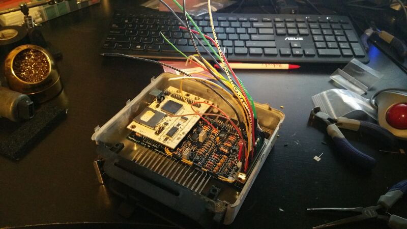
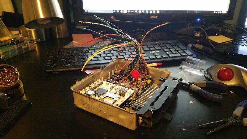
I have been following and using this thread for the past few months as I am attempting to install MS3 Base v3.0 into my 88' 944 turbo. The car had MS on it with the previous owner and now that I have it and several hardware items have been taken care of for me, I am attempting to take a more custom approach to the install to make it as clean as possible. This thread has been very valuable to me, especially all of the information that Doug951S has posted. Although the MS3 base requires that I build the board DIY, which I really enjoyed, its not far off from what you have done. I am taking a similar approach to install as well as I had a spare, dead mind you, DME laying around that I gutted for the case and 35 pin connector. When I got the MS board in the mail, I took the cover off the DME and noticed how nicely the board fits in the ECU.
So at this point I have built the board and most of the patch harness between the 35 pin DME and the MS DB37, however I have some questions about wiring....hope you all can help me out. Apologies if some of these are obvious or have already been answered, I read through the thread quite a bit and did not see these specific questions answered yet.
1. I want to retain the PWM IAC valve if I can, I just want the car to run the best it can and I have heard running without IAC can have cold start reprocussions. That said, the bosch unit is a 3 wire, which the MSX guide really sucks at depicting correct wiring for. Here is what I have so far. The PWM kit is installed. I plan to wire DME pins 33 & 34 to drive the unit from megasquirt. MSX guide HERE shows that I need to wire one of the pins to the PWM signal on MS (PIN 30), the center to 12V switched, and the other side to ground with a 50Watt 40 ohm resistor inline. I plan to do this but I am unsure of which pins to wire to ground DME 33 OR 34 for correct operation. I get the resistor after xmas so I will test but I am unsure which pin on the IAC i should ground out and which one I should drive 3 or 5? I also thought about driving it with two PWM modules using the Zeal Engineering board, so if you all have opinions on one way or another, I am not too far along to change it.
2. Tacho output, I plan to use the factory coil/distributor to get the car started using the bip373 kit the MS3 came with but have full plans of moving to wasted spark very soon, in fact I pulled 4 D585 coils from a chevy 1500 last week at LKQ. My question is will the factory tachometer in the dash still work? on older bimmers that have done MS builds they actually have to wire one of the outputs (JS#) to power the tach...is this the case with an 80's porsche too? I have the outputs and actually already have JS1 wired up to one of my spare IAC stepper pins, IAC2B I think, and can easily power the tach but am unsure of which DME pin it should be connected to. I plan to connect the MS pin 36 to drive the coil as I have seen everywhere, am I missing something or is the tach good to go?
3. I have plans of running the fans off of MS as well and doing away with the finicky old fan resistors. I have an external relay I was planning on running and just cutting the fans electrical connector and running it back to the relay, but its a bit invasive and seeing as how I would really like to reuse as much of the wiring as I can I was hoping to get a pointer or two from you guys on how exactly your factory fans are run back to the MS or wiring harness in the car? specifically, I am looking to understand where I can tap the fan signals to switch them on and off.
4. I know I digitally calibrate the TPS once it is wired up but should I be using the DME pins for WOT and closed throttle for TPS signals? The wiring diagram makes it seem as if its closed or open signals that just go high when activated, but I know that this thread states the 951 TPS works great with MS. Just some clarity here would be helpful.
For ref, here is what I am putting it into
1988 944 Turbo:
Garrett T04e 57 Trim
Tial 40mm ->open dump
3" DP -3" to axle - 4" axle back
55 lb/hr low imp injector with resistor pack
3 bar FPR + a few other goodies.
I am planning on using my MS2 that I built a few years ago in my 87 turbo, waiting to hear back from doug on the coils he is using. I would like to do coil on plug but not sure which ones to use. I will be doing away with as much stock wiring as I can and I intend on controlling boost and knock as well as the cooling fans.
SpeedFrk not sure were you will tap into the stock DME plug for the tach but there is a plug in the stock wiring that goes to it I will dig through the info I have saved and post it later when I can. I can probably be of some help to you on the fans as well as I have delt with them on may earlier 944's feel free to PM me and maybe we can exchange phone numbers and talk. I am not the greatest writer.
I'm using LSx coils guys. You can get em off any lsx or vortec serties engines. Camaro/firebird, trucks, corvettes, ect. They are a dime a dozen, I got 8 coils for like 10 bucks from a junkyard.
1. I want to retain the PWM IAC valve if I can, I just want the car to run the best it can and I have heard running without IAC can have cold start reprocussions. That said, the bosch unit is a 3 wire, which the MSX guide really sucks at depicting correct wiring for. Here is what I have so far. The PWM kit is installed. I plan to wire DME pins 33 & 34 to drive the unit from megasquirt. MSX guide HERE shows that I need to wire one of the pins to the PWM signal on MS (PIN 30), the center to 12V switched, and the other side to ground with a 50Watt 40 ohm resistor inline. I plan to do this but I am unsure of which pins to wire to ground DME 33 OR 34 for correct operation. I get the resistor after xmas so I will test but I am unsure which pin on the IAC i should ground out and which one I should drive 3 or 5? I also thought about driving it with two PWM modules using the Zeal Engineering board, so if you all have opinions on one way or another, I am not too far along to change it.
I'm not familiar with how the the PWM IAC valves are controlled by MS. In my case, I used a factory early 944 idle air valve ("auxiliary air valve") and gave it power whenever the fuel rail has power, exactly like how the Motronic had it. Idle is great, no problems, it's not controlled by MS so no configuration. If you want to use a PWM IAC, there are 2 things you could do that are alternatives to getting the stock part to work. 1) you could ditch it for a 2-pin valve, where polarity doesn't matter. Again, you just change the settings until the idle is where you want it. 2) use a Bosch PWM IAC that someone on the MSExtra forums can already confirm works well with MS and has info for. Google showed me a couple last time I looked.
Originally Posted by SpeedFrk
2. Tacho output, I plan to use the factory coil/distributor to get the car started using the bip373 kit the MS3 came with but have full plans of moving to wasted spark very soon, in fact I pulled 4 D585 coils from a chevy 1500 last week at LKQ. My question is will the factory tachometer in the dash still work? on older bimmers that have done MS builds they actually have to wire one of the outputs (JS#) to power the tach...is this the case with an 80's porsche too? I have the outputs and actually already have JS1 wired up to one of my spare IAC stepper pins, IAC2B I think, and can easily power the tach but am unsure of which DME pin it should be connected to. I plan to connect the MS pin 36 to drive the coil as I have seen everywhere, am I missing something or is the tach good to go?
Check out my post on page 4 of this thread, under "maintaining gauge functionality." In short, the stock tach triggers off the stock ignition coil, despite the errant posts/graphics about a tachometer pin on the DME. When you go to alternative ignition, of course you'll need to work around that. The post I referred to has the info you need, let me know if you need more details.
Originally Posted by SpeedFrk
3. I have plans of running the fans off of MS as well and doing away with the finicky old fan resistors. I have an external relay I was planning on running and just cutting the fans electrical connector and running it back to the relay, but its a bit invasive and seeing as how I would really like to reuse as much of the wiring as I can I was hoping to get a pointer or two from you guys on how exactly your factory fans are run back to the MS or wiring harness in the car? specifically, I am looking to understand where I can tap the fan signals to switch them on and off.
My approach was to install a relay in place of the radiator fan switch. It's easy and leaves the wiring intact. You obviously leave the fan switch physically installed, but you use its connectors on a relay instead, which is controlled by MS. I opted to mount the relay in the cabin and run wires up to the front. I also make an adaptor harness (which meant cuttung factory wiring) to switch between the fan switch and MS fan control. I've been running this setup for months now, driven almost daily, with no problems and always rock solid temps.
Originally Posted by SpeedFrk
4. I know I digitally calibrate the TPS once it is wired up but should I be using the DME pins for WOT and closed throttle for TPS signals? The wiring diagram makes it seem as if its closed or open signals that just go high when activated, but I know that this thread states the 951 TPS works great with MS. Just some clarity here would be helpful.
Actually you don't want to mess with either of those pins. There are 3 pins on the TPS you need to worry about: 1, 2, and 3 (4, 5, and 6 are unused). Refer to my post on page 4 of this thread for the wiring. The only function of the TPS that MS sees is the potentiometer, the idle and WOT switches are seperate functions.
Well I got the 3 Wire stock PWM IAC to work!! I used the 50 watt resistor and everything worked great on my test bench. I am able to adjust the coolant temp pot on my stim and it auto changes the duty cycle on the IAC. Let me know if anyone is interested in using the stock IAC and didnt understand what I did from my last post.
Check out my post on page 4 of this thread, under "maintaining gauge functionality." In short, the stock tach triggers off the stock ignition coil, despite the errant posts/graphics about a tachometer pin on the DME. When you go to alternative ignition, of course you'll need to work around that. The post I referred to has the info you need, let me know if you need more details.
Ok, so I read your posts and they are a bit helpful but I still have questions. Does the DME pin 11 not provide the signal for the stock tach guage? I plan on running a 60/2 reluctor wheel, which came with the car, and a VR sensor from a for explorer (4.0L) that I pulled from a junkyard. This VR signal will allow me to output a tach signal onto one of my AUX pins, specifically I have mine wired to IAC2B(Pin31) via JS0(See the image below). So I had planned on wiring DME pin11 to this signal and setting JS0 up to output the RPM signal. Am I doing this wrong? Initially I plan to run the distributor and the factory harness so I most likely will not need this initially, but I already have GM LS coils sitting here that I plan to install after I get the car running, I am trying to do this in stages to make it simpler for my mind . So when I go to the LS coil setup I will need to wire that tach signal to something, is that DME pin11 or is it the in the connector near the brake booster you ref on pg 4? Sorry i'm confused.
My approach was to install a relay in place of the radiator fan switch. It's easy and leaves the wiring intact. You obviously leave the fan switch physically installed, but you use its connectors on a relay instead, which is controlled by MS. I opted to mount the relay in the cabin and run wires up to the front. I also make an adaptor harness (which meant cuttung factory wiring) to switch between the fan switch and MS fan control. I've been running this setup for months now, driven almost daily, with no problems and always rock solid temps
Thanks for this info as well, I was planning on using the fan setup shown in the image below which requires me to put a 2N2222A transistor and a 1kohm resistor onto IAC1A (MS Pin25) and run that out to the relay, but what I did not understand is where to run the wire for pin 87 out to the fan into on the harness. Is this the fan switch outputs that you twisted together? Now I know you are using Microsquirt and your wiring is probably different but there is something you did that I dont understand. Your image in that link shows you wired relay pin 85 to the MS and that is provided a ground signal, how did it do this? I can wire any auxiliary output, I have many, to any open pin on the connector to create a going high or going low signal to switch the relay on or off. Is this what you were doing with pin 85?
Also, the 944 turbo fans are 2 speed via the fan resistor pack located in the fire wall, if I am mistaken please jump all over me here, and I wonder is this 2 speed functionality retained using your method? if it is not and your only supplying a on/off signal which speed do the fans come on at when the coolant temp set point is reached?
Actually you don't want to mess with either of those pins. There are 3 pins on the TPS you need to worry about: 1, 2, and 3 (4, 5, and 6 are unused). Refer to my post on page 4 of this thread for the wiring. The only function of the TPS that MS sees is the potentiometer, the idle and WOT switches are seperate functions.
Thanks for this tidbit, I looked at your wiring instructions and everything makes sense, only thing I dont understand is how that is tied into the factory harness. Doug951S, can you elaboration on how you read TPS through the 35 pin DME plug? specifically which DME pins do you use to gain signals for pins 123 as Odonnell suggests?
Thanks for your help here guys, I feel like I am getting very close to install in the car, which has its own set of tasks but its a good feeling. I have not worked on the car in a while, just soldering and testing.
Some guy named Matt's wiring diagram I have been using as it mimics my desired setup.
Last edited by SpeedFrK; 12-27-2015 at 06:25 PM.
Reason: Forgot an image.
Pin 11 doesn't tell the tach anything. It's a square wave, used for the economy gauge. The tach signal actually comes from pin #1, which is is a ground for the coil. There is a branch off of the coil's ground wire (green) that goes to the tach (also a green wire). In an early car, this is behind the brake booster. The circuit in the tach knows that for every 2 coil firing events, 1 revolution has occurred. So while you have the stock coil and dizzy, you won't have a problem because the tach still sees those firing events.
But you can see that when you no longer are pulsing the coil via Pin 1, you'll need to recreate the tach signal. In your case, you would just run the tach output wire from Megasquirt to Pin 1 on your gutted DME (of course, only after you switch to the coils). Then just make sure you seal off the connections that went to the stock coil so there's no short circuit against the frame over there. The default tach signal seems to work fine, mine is just as responsive (if not moreso) than stock and is more accurate. Stock tach signal is a little optimistic.
Re: fan control
The early fan switch has 2 contacts, I removed them from the fan switch and put them on pins 87 and 30 of the relay. Order doesn't matter, those pins will "complete the circuit" when MS turns on the relay, just like the stock fan switch. My twisted-pair wiring just extends the stock harness into the cabin, where I located the relay. If you do this in place of the fan switch you'll lose multi-speed functionality, they will just be on or off. But you could use 2 spare outputs and stage the relays, one with a resistor, to recreate that if you really wanted to.
MS grounds one of the activation pins (85 or 86, doesn't matter) and the other activation pin gets switched +12v. I'm not sure how about the transistor and resistor, I don't believe you need that for activating a relay, as it's very low current draw.
Re: TPS
I don't see a pin on the 951 DME pinout for the TPS potentiometer signal so you may just to run a separate mini-harness out to it.
I don't see a pin on the 951 DME pinout for the TPS potentiometer signal so you may just to run a separate mini-harness out to it.
Also, Re: The TPS signal is sent through the KLR on the 951, since it looks at the full load signal and uses that as part of it's knock detection routine. Because of that, as Michael stated you will not find a TPS signal out pin from the DME harness, you must take that off the KLR harness. I forget off the top of my head exactly which pin it is.
Pin 11 doesn't tell the tach anything. It's a square wave, used for the economy gauge. The tach signal actually comes from pin #1, which is is a ground for the coil. There is a branch off of the coil's ground wire (green) that goes to the tach (also a green wire). In an early car, this is behind the brake booster. The circuit in the tach knows that for every 2 coil firing events, 1 revolution has occurred. So while you have the stock coil and dizzy, you won't have a problem because the tach still sees those firing events.
Yea sorry about that I meant pin 21 on the same pin out you reference which is "conn point 4-pin term 2 (Tachometer-1)". I was thinking that pin would be the signal for the tach. Thanks for the clarification.
Doug951s,
Thanks for the clarification on the TPS signal. Based on your input and the wiring diagrams Odonnell refers to I believe its pins 21 through 23. I suppose Ill have to do some harness hacking, which I was trying to avoid, but atleast there is a way to get the signals in the foot well now. Thanks again.
Last edited by SpeedFrK; 12-27-2015 at 06:43 PM.
Reason: missed something
Yea sorry about that I meant pin 21 on the same pin out you reference which is "conn point 4-pin term 2 (Tachometer-1)". I was thinking that pin would be the signal for the tach. Thanks for the clarification.
Doug951s,
Thanks for the clarification on the TPS signal. Based on your input and the wiring diagrams Odonnell refers to I believe its pins 21 through 23. I suppose Ill have to do some harness hacking, which I was trying to avoid, but atleast there is a way to get the signals in the foot well now. Thanks again.
21-23 sounds right, +5Vdc, ground, and signal though I'm not sure which is which. You give the TPS +5Vdc from Vref+ like all the other powered sensors; then the ground comes back to MS via the low power common. I opted to run a separate mini harness like Michael described, with a 470 uf capacitor inline between Vref+ and sensor ground to attenuate noise.
I run a 470 uf cap between Vref+ and sensor common on the MAP sensor as well, for the same reason.
Which DME pin did you use to wire in the fuel pump relay? Or did you just keep the DME relay which switches on the FP relay? Am I right here and in this case the factory harness handles the FP switching? MS pin 37 is the one I am concerned with as in a custom wired setup like Odonnell's its wired directly to the FP relay.
Did you know MS has integrated knock control? It's true, is has basically the same functionality as the factory KLR, except with finer control and a much higher sampling rate. For NA cars, it adds functionality that the car never originally had.
For starters, go check this site out http://www.viatrack.ca/
since they sell the MS knock box you'll need to implement knock control with MS. You'll want to reuse the factory knock sensor, NA cars will need to drill the boss where the 951 unit is placed on the head and install and wire up a factory sensor.
You'll need to provide viatrack with some info on the car since each MS knock unit is custom tuned to the particular engine it is going on.
Here is the knock sensing table
The MSknock box will feed the binary "yes/no" knock signal into the MS via your choice of a multitude of spare input pins.
You'll want to set the "knock ignored above MAP" setting to over 105 kpa for an NA car and over your maximum boost on a boosted car. Other wise MS might miss knock counts at high boost, which would defeat the purpose.
You can also set the rpm window to ignore knock counts below a certain rpm, say 3500 rpm for a boosted car since below that you will not get more than 100 kpa in the manifold.
It's worth noting that the knock senseing/timing retard function is MS can operate in two modes, "safe" mode and "aggressive" mode. The data fields are all fairly self explanatory here, the retarding section describes the maximum amount of timing MS can pull out, how often it will check for knock and continue to pull timing if still detected, and the amount of timing pulled out each time is makes a correction when it detects knock. The advance section describes how the ECU recovers back to normal timing after knock is no longer detected.
In general this system works MUCH better than the factory KLR, I encourage everyone to invest in a MS knock unit and set up this functionality.
This, along with the overboost protection described in an earlier post essentially eliminates the possibility of a non-mechanically related engine failure or engine damage and makes the tune way safer than any motronic based tune.
Do you happen to know if I can feed the knocking yes/no output pin (KLR PIN 15) into MS instead of purchasing this external knock sensing unit? I figure it would be lower resolution but would it not still provide the necessary information?

 12-09-2015, 11:16 PM


 to install MS3 Base v3.0 into my 88' 944 turbo. The car had MS on it with the previous owner and now that I have it and several hardware items have been taken care of for me, I am attempting to take a more custom approach to the install to make it as clean as possible. This thread has been very valuable to me, especially all of the information that Doug951S has posted. Although the MS3 base requires that I build the board DIY, which I really enjoyed, its not far off from what you have done. I am taking a similar approach to install as well as I had a spare, dead mind you, DME laying around that I gutted for the case and 35 pin connector. When I got the MS board in the mail, I took the cover off the DME and noticed how nicely the board fits in the ECU.