When you click on links to various merchants on this site and make a purchase, this can result in this site earning a commission. Affiliate programs and affiliations include, but are not limited to, the eBay Partner Network.
I'm glad you posted this because I learned this very thing last Thursday when I pulled all the carpet and the ECU cover to find the 997.1 Bosch unit was a very different setup than the DFI's. You're supposed to know everything, Tom!
If I find a solution before you do (not likely) I'll post here.
Edit: Found it. Second Edit: I should note that there are two ways to do this in a system such as this. The first it to tap the signal send to the CPU via the sensor which is described here. The second is to tap the signal from the ECU to the instrument cluster. This can be harder because that signal is usually a translated signal of varying resistance that may not be linear (unlike the sensor signal). Furthermore that second signal is also translated again at the instrument cluster side before sending another linear signal to the tach needle. So, the best methods are to either tap the signal from the sensor or the tach and the tach is, IMO, not worth messing with and taking apart and mapping when you have a nice easy signal directly from the flywheel sensor. Third Edit: This is also taking the HUGE assumption that the Shift-i has the algorithms to translate a direct from flywheel signal to the pretty lights on the shift-light pod.
Moving on...
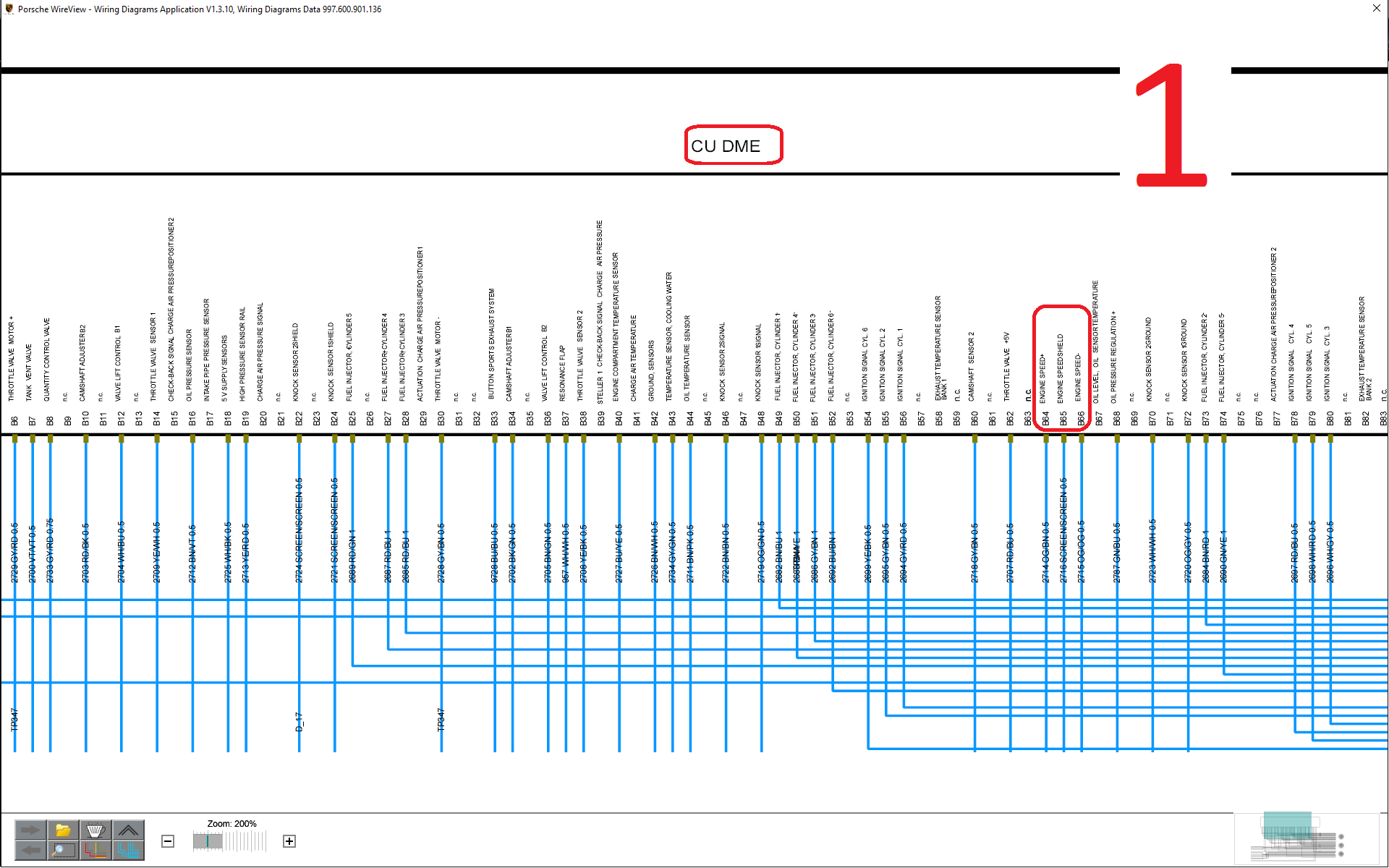
The 9A1 ECU has two main connectors. (A) and (B). (B) measures/controls the engine functions.
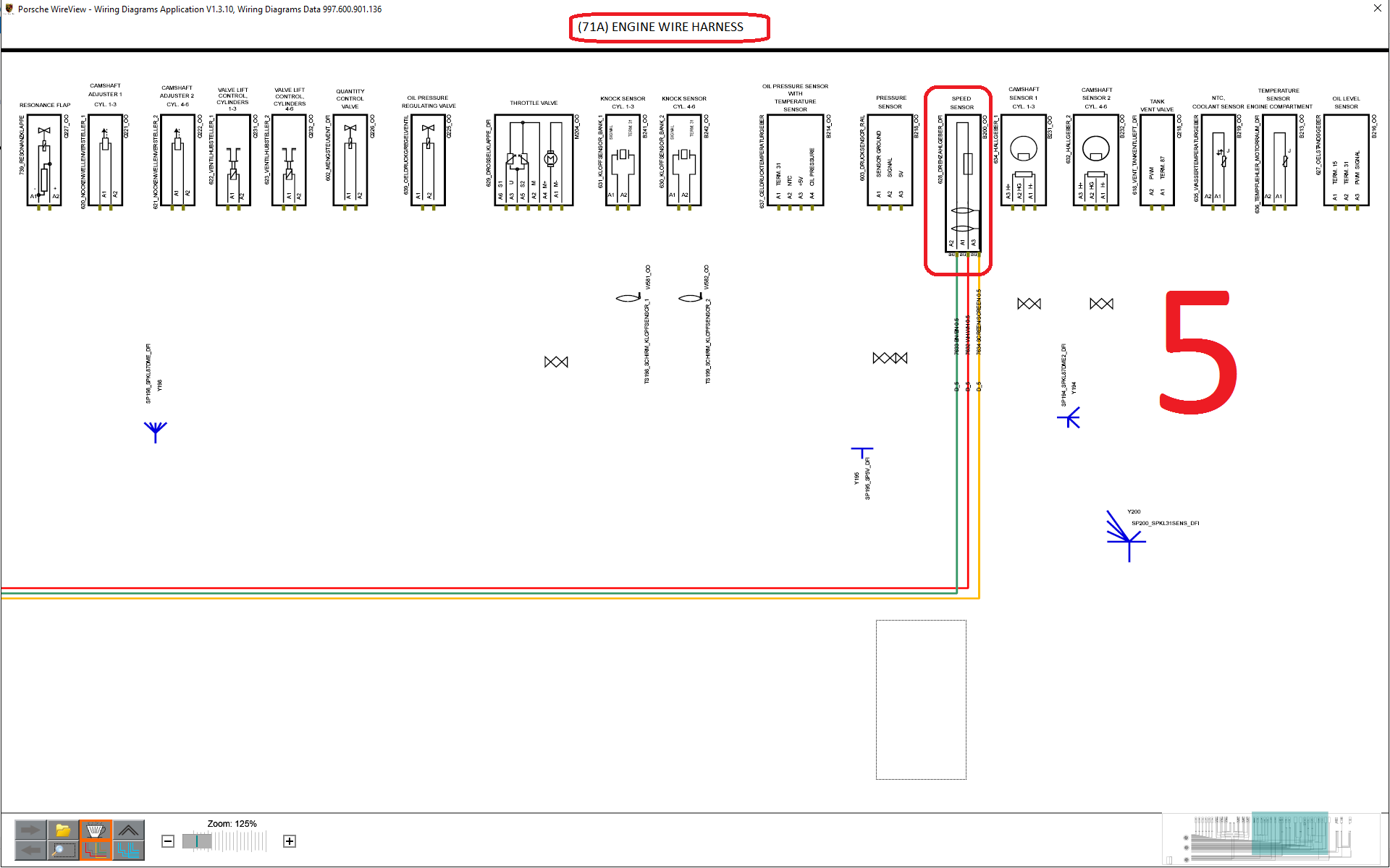
Diagram (1)
The input from the engine speed sensor (via the engine wiring harness) is at terminals B64, B65, B66. B65 is just a shield. The sensor at what I imagine is the flywheel is completing a circuit at varying resistance through terminals B64 and B66.
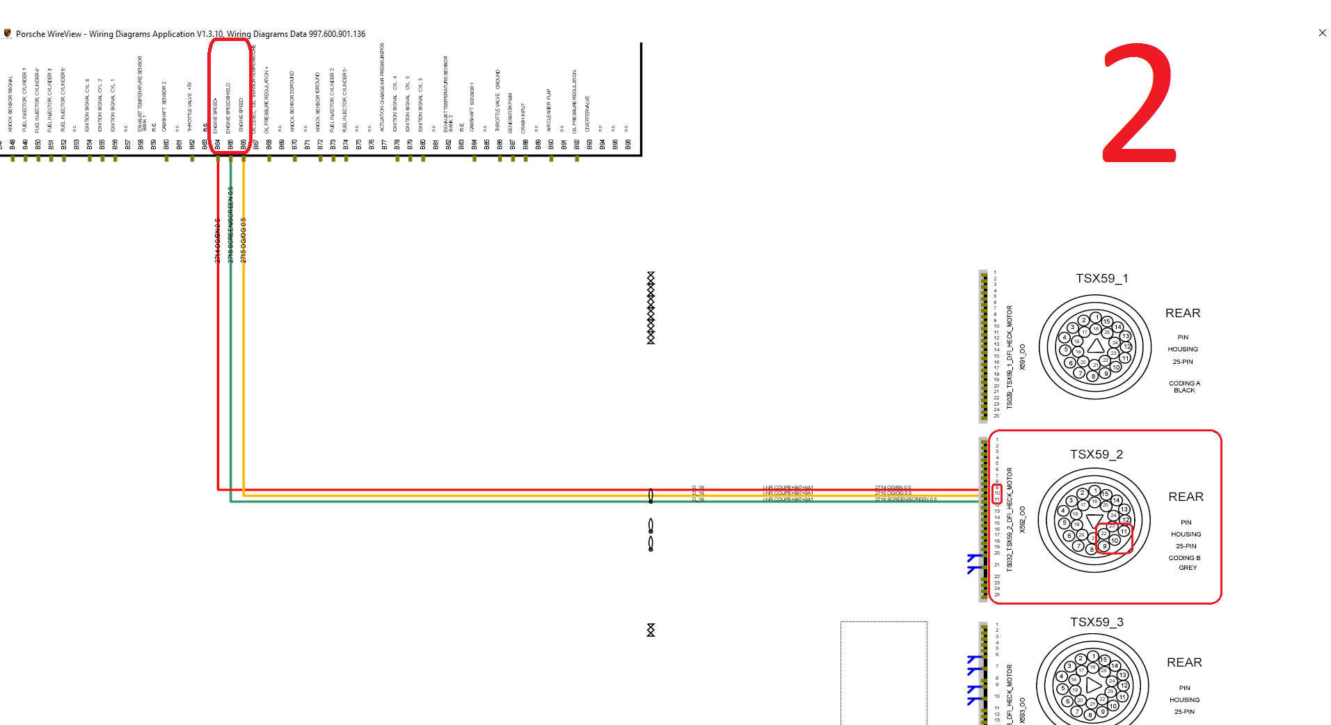
Diagram (2)
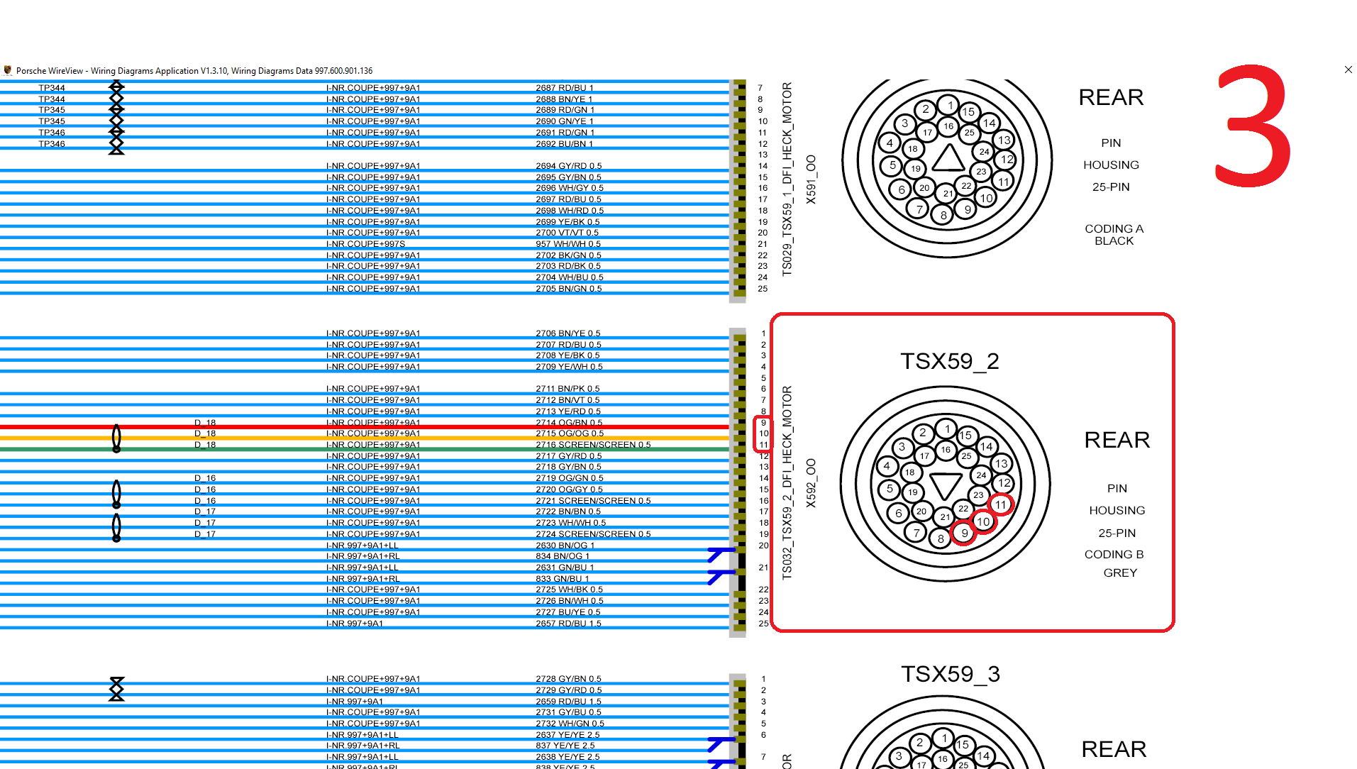
Here is the route in the interior wiring harness before it plugs into the engine wiring harness. Our pals B64 and B66 coincide with terminals 9 and 11 (HA!) at the interior plug as seen in Diagram (3)
Diagram (4) shows the path at the engine wiring harness plug end with the same 9 and 11 terminals/leads. 10 is the shield.
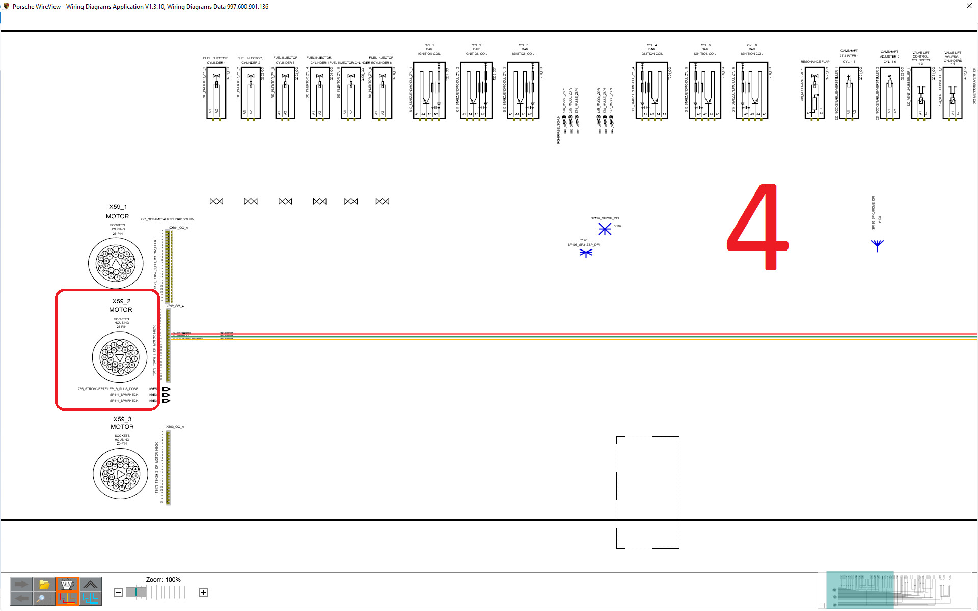
Diagram (5) Shows the path to our little drehzahlgeber (speed sensor) probably at the flywheel.
So this would be a good analogue tapping point at the interior wiring harness at terminals B64 and B66. Now to figure out which one to tap, (+) or (-). Just so I can plan ahead, anybody buying bricked ECUs?
Thanks for finding and sharing the info. You're da man!
If I was doing this, I would prefer to junction to an ignition coil trigger wire. According to the first image its one of the following pins: B54, B55, B56, B78, B79, B80. The reason why I would use an ignition coil trigger wire is because its on the output side of the ECU and the possibility of a fault that would cause the engine to not start is significantly less than using a primary input signal for the ECU. In event of the shift light device or its wiring develop a short circuit over time this way the effect is isolated to one ignition coil, not the entire engine. Just my logic.
__________________
PCA National Instructor
TPC Racing stats:
2023 Porsche Sprint Challenge 992 Cup Am Champion
2023 Porsche Sprint Challenge GT4 Pro-Am Team Champion
2022 Porsche Sprint Challenge 992 Cup & 991 Cup Champion
2020 IMSA GT3 Cup Challenge 2nd Championship
2018 IMSA GT3 Cup Challenge 2nd Championship
2016 IMSA GT3 Cup Challenge Champion
2013 IMSA GT3 Cup Challenge Champion
2006 Rolex-24 @ Daytona GT Champion
2004 Grand-Am SGS Class Champion
Thanks for finding and sharing the info. You're da man!
If I was doing this, I would prefer to junction to an ignition coil trigger wire. According to the first image its one of the following pins: B54, B55, B56, B78, B79, B80. The reason why I would use an ignition coil trigger wire is because its on the output side of the ECU and the possibility of a fault that would cause the engine to not start is significantly less than using a primary input signal for the ECU. In event of the shift light device or its wiring develop a short circuit over time this way the effect is isolated to one ignition coil, not the entire engine. Just my logic.
Yes, I didn't factor what a possible short would do. I'd have an inline fuse that would prevent a short and still maintain signal if i did short but better to be safe that sorry.
Also, sorry for hijacking your great thread. I'll take this to a separate thread from now on for this project.
I will very likely get flamed by members who just want a simple answer of a set of recommended values. The truth is I don't have a set of recommended values.
I don't think anyone who has spent time tuning and adjusting their car would think you're crazy. As you said - every driver is different, every car is different, the same car and same driver will require different values on different days. As I think you know, the info I provided was more just to serve as a reference that adding more negative camber along with the other changes yielded a positive benefit for me.
I don't think anyone who has spent time tuning and adjusting their car would think you're crazy. As you said - every driver is different, every car is different, the same car and same driver will require different values on different days. As I think you know, the info I provided was more just to serve as a reference that adding more negative camber along with the other changes yielded a positive benefit for me.
Glad you feel the same way. And glad you formulated specs that you're happy with. Thanks for sharing the data.
Yes, I didn't factor what a possible short would do. I'd have an inline fuse that would prevent a short and still maintain signal if i did short but better to be safe that sorry.
Also, sorry for hijacking your great thread. I'll take this to a separate thread from now on for this project.
Just wanted to follow up on the rear vents you cut into the heat shield to allow the bumper vents to actually be functional. Any adverse affects you have seen from this? I'm wondering why it didn't come like this from the factory. Not even either generation of the cup cars has it done either.
Just wanted to follow up on the rear vents you cut into the heat shield to allow the bumper vents to actually be functional. Any adverse affects you have seen from this? I'm wondering why it didn't come like this from the factory. Not even either generation of the cup cars has it done either.
Been working fine for me. Only bad thing is back of the car gets dirty after one drive. I'd not do it for street use only. Some of the cup teams remove the coverings where the racing sanctioning bodies allows. The RSR's are pretty opened up back there.
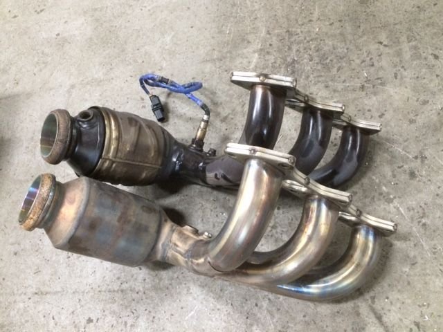
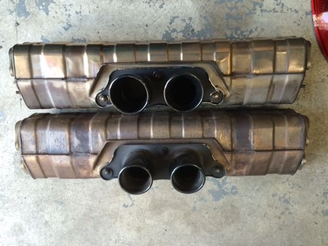
Scored a set of used 997.2 Cup headers w/ 100 cell cats. Going to put them on soon(after emissions testing...cough, cough). Here's what they look like side by side with the OEM .1 headers.
Dimensionally they're the same. Just lacking the fitting for secondary O2 sensors.
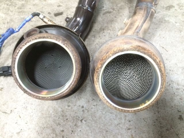
Biggest difference is the cats.
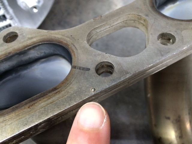
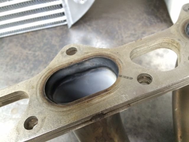
On one particular used Cup headers I spotted a piece of weld on the mating flange that isn't suppose to be there. The thickness of the weld is greater than the thickness of the gasket. Maybe that was why someone drew a black line that port to indicate an exhaust leak.
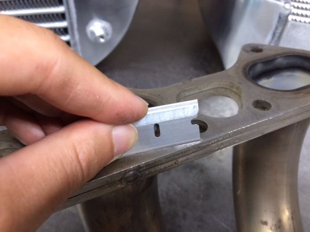
Very gentle touch with a carbide smoothed it out.
Flange is flat as a razor blade.
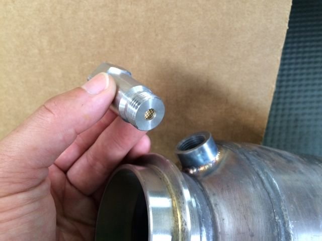
Lastly, welded on the secondary O2 fittings. And just for fun I'll be trying on these O2 "extenders" that I got on ebay.
Stay tuned for dyno results.
I wanted to convey that there are fine choice of race headers available from TPC, Dundon/RK, Porsche Motorsports...for those who have the means. What I'm doing is nowhere near as good as these high quality race headers. I'm just doing an experiment with used parts within my measly budget.
These work. Very durable, looks "stock" etc... I put the bung in mine.
You'll probably get codes. Just have your tune raise the post cat thresholds or turn off the cel readiness test. With Cobb it's easy to go back and forth.
Quick feedback on the exhaust changes before heading off to Watkins Glen for PCA Potomac HPDE.
I installed the 997.2 Cup headers(100cell cat) definitely added more sound volume and made the engine feel more snappy. The sound, as expected, made my street car sound closer to a Cup. Unfortunately I didn't get a chance to dyno, been swamped with prepping customer cars and IMSA races... but will do it when I return from WG.
Here are some pic of the headers and OCD afterhour car prep...
Before and after. I'd prefer full race headers but I got these used and they fit my budget. Made a strap for extra margin of security.
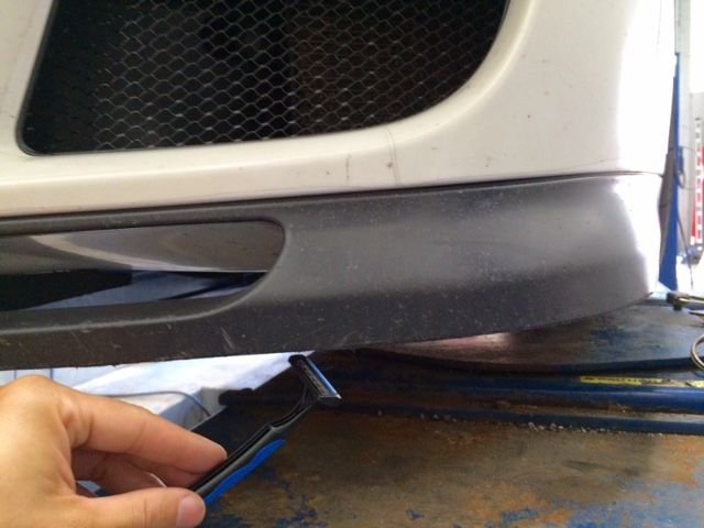
Smooth chin
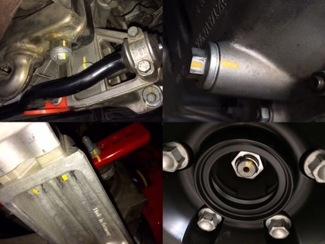
Torque and paint mark everything.
Everything.
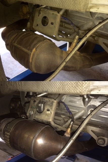
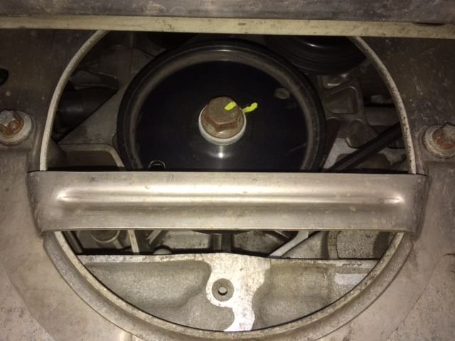
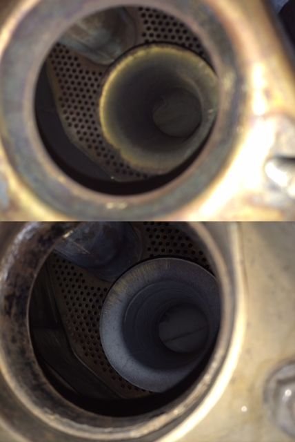
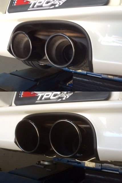
The day after I installed the headers(and prep) I replaced the 9-year old 997.1 center muffler with a used 997.2/991 one. With used 991 tips. The two muffler are dimensionally the same outside(except for the tips)
The shape of the venturi look to be different. Top is the 997.2/991 venturi.
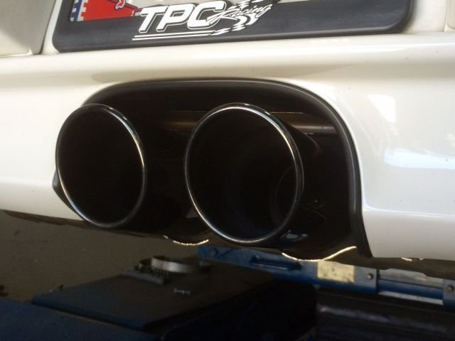
Loving the look of the 991 tips!
Sound wise, the .2 muffler added another ~5% more sound volume at idle. Sounds more "boomy" 2800-3000rpm cruising in 6th gear. But love the sound at WOT! I did a down shift/blip every time driving under a bridge to hear teh echo!
Heading out. Wish me luck at WG. Been there number of times as a crewman, first time as a driver. I'll bring a 991 and a 997.2 DSC module to WG for demo.


 04-21-2016 | 10:58 AM
 Found it.