When you click on links to various merchants on this site and make a purchase, this can result in this site earning a commission. Affiliate programs and affiliations include, but are not limited to, the eBay Partner Network.
To use both antennas in the Cayenne, you need the Y-splitter. I originally ordered the wrong one by mistake and so,only had one antenna hooked up for about a week. Hooking up both antennas improves reception and makes the radio less sensitive to the direction that the car is pointed. For example, a station might come in well when headed East, but not when headed West. With both antennas connected it will work well in either direction. Worthwhile to get the connector.
To use both antennas in the Cayenne, you need the Y-splitter. I originally ordered the wrong one by mistake and so,only had one antenna hooked up for about a week. Hooking up both antennas improves reception and makes the radio less sensitive to the direction that the car is pointed. For example, a station might come in well when headed East, but not when headed West. With both antennas connected it will work well in either direction. Worthwhile to get the connector.
cheers,
c
Thanks, for the input but how about those red, green and yellow/brown wires? where do those go? I think the two orange ones go to the dual green, green black.....
2006 CTTS with Bose and factory motorized backup camera
I just installed the Seicane Android 8.0. I have two issues that I'm hoping someone may have the answer to.
1. I had the factory camera working great for 1 whole day and then it stopped working, I haven't had a chance to open everything back up and look for burnt wires but I will explain how I wired it and hopefully we can spot the error together. I used a 12Vdc SPDT relay. The 86 contact is RELAY COIL IN so I spliced it to the orange REVERSE IN wire on the android power harness. The 85 contact is RELAY COIL OUT so I spliced it to ground. The 30 contact is the signal getting passed through the relay; the factory camera motor operates when grounded so I spliced contact 30 to ground (the same ground as contact 85). The 87a contact is the signal connected to the 30 contact when the coil is NOT getting 12Vdc so I didn't connect anything to contact 87a. Contact 87 connects to contact 30 (which is ground) when the coil is energized (car in reverse) so I connected contact 87 to the blue wire on the porsche factory power harness (factory camera motor wire). I feel like the logic is sound... and it definitely worked the first 3 times I turned the car on and went into reverse. Did anyone else successfully use the factory camera and remember if they wired the relay identically or differently?
2. I used a y split fakra and connected both factory antenna fakras to it. I then put the other end of the y splitter cable into the Seicane antenna port. Radio is pretty much nonexistent on both AM and FM. Where did I go wrong? Am I missing another cable that amplifies? Do I need to connect the blue wire on the splitter to anything?
A sincere thank you to everyone that has participated in this upgrade and written about it. This was 1,000,000% worth it and I wouldn't have done it without you guys. Thanks to advice of others I put the Seicane GPS module by the speaker in the dead space above console ACs. GPS signal is great and I ran zero wires to fuse box and zero wires to anywhere else in the vehicle. Hopefully we can create a new thread that gives 100% foolproof instructions so people don't have to read this and 20 other threads to find the nuggets needed. I plan to install a unit on my 2006 CTT with Bose and factory camera as well; maybe that can be our instructional walkthrough... lmk if interest is there.
Last edited by Jonathan H; 08-16-2018 at 05:23 PM.
Reason: swapped 87a and 87
Thanks, for the input but how about those red, green and yellow/brown wires? where do those go? I think the two orange ones go to the dual green, green black.....
They might not go anywhere and/or they might not need to go anywhere. Are there pins in those locations on the head unit socket? Post #458 *may* have the info you seek.
2006 CTTS with Bose and factory motorized backup camera
I just installed the Seicane Android 8.0. I have two issues that I'm hoping someone may have the answer to.
1. I had the factory camera working great for 1 whole day and then it stopped working, I haven't had a chance to open everything back up and look for burnt wires but I will explain how I wired it and hopefully we can spot the error together. I used a 12Vdc SPDT relay. The 86 contact is RELAY COIL IN so I spliced it to the orange REVERSE IN wire on the android power harness. The 85 contact is RELAY COIL OUT so I spliced it to ground. The 30 contact is the signal getting passed through the relay; the factory camera motor operates when grounded so I spliced contact 30 to ground (the same ground as contact 85). The 87 contact is the signal connected to the 30 contact when the coil is NOT getting 12Vdc so I didn't connect anything to contact 87. Contact 87A connects to contact 30 (which is ground) when the coil is energized (car in reverse) so I connected contact 87A to the blue wire on the porsche factory power harness (factory camera motor wire). I feel like the logic is sound... and it definitely worked the first 3 times I turned the car on and went into reverse. Did anyone else successfully use the factory camera and remember if they wired the relay identically or differently?
2. I used a y split fakra and connected both factory antenna fakras to it. I then put the other end of the y splitter cable into the Seicane antenna port. Radio is pretty much nonexistent on both AM and FM. Where did I go wrong? Am I missing another cable that amplifies? Do I need to connect the blue wire on the splitter to anything?
A sincere thank you to everyone that has participated in this upgrade and written about it. This was 1,000,000% worth it and I wouldn't have done it without you guys. Thanks to advice of others I put the Seicane GPS module by the speaker in the dead space above console ACs. GPS signal is great and I ran zero wires to fuse box and zero wires to anywhere else in the vehicle. Hopefully we can create a new thread that gives 100% foolproof instructions so people don't have to read this and 20 other threads to find the nuggets needed. I plan to install a unit on my 2006 CTT with Bose and factory camera as well; maybe that can be our instructional walkthrough... lmk if interest is there.
I'm having a problem understanding #1 (and I'm an old time electronics guy..) a diagram might be helpful.
I'm trying to make sense of what you're doing.
Looking at the camera wiring - do we know if the blue output from the camera control unit is put to ground to make the camera extend?
What does the orange "Reverse In" connection on the Android cable expect to see as input? Or what does it output?
Need answers to those questions to make an intelligent comment. Right now - it really is confusing.
Oh - on the factory antenna - there are two antenna amplifiers that have to get power from somewhere now that the PCM is out of the circuitry.. if they're not being powered up chances are excellent you'll basically have no signal.
Hopefully we can create a new thread that gives 100% foolproof instructions so people don't have to read this and 20 other threads to find the nuggets needed. I plan to install a unit on my 2006 CTT with Bose and factory camera as well; maybe that can be our instructional walkthrough... lmk if interest is there.
Yes please. 40+ pages on this thread + other threads is a bit of a mess to go through.
I'm having a problem understanding #1 (and I'm an old time electronics guy..) a diagram might be helpful.
Thank you for the reply and for the camera control unit wiring diagram! I have never seen that one. I made a mistake in my explanation that messed up your diagram. Relay not energized should connect 30 to 87a. Relay energized should connect 30 to 87. I connected blue factory wire to 87 so that it gets grounded to 30 when in reverse. I am going to edit my previous post to reflect this because I don't want future people reading something so wrong.
It worked fine the first 4-5 times I started up the car and went into reverse.
Looking at the camera wiring - do we know if the blue output from the camera control unit is put to ground to make the camera extend?
The factory blue wire is always +12Vdc. When this wire is touched to any ground the motor operates (rotates out the coo coo clock camera).
What does the orange "Reverse In" connection on the Android cable expect to see as input? Or what does it output?
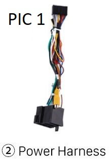
Orange wire on android power harness is labelled "Reverse In" (I think it was a pigtail). It outputs +12Vdc when the car is thrown into reverse. I did not check to see what factory wire the signal came from; I just put a multimeter on it and went into reverse. Here are two photos from seller than I cropped to info that may or may not be helpful:
Oh - on the factory antenna - there are two antenna amplifiers that have to get power from somewhere now that the PCM is out of the circuitry.. if they're not being powered up chances are excellent you'll basically have no signal.
I just ordered another Y splitter that does 2 fakra males (connected to porsche fakra females) and on the other side a fakra female (to connect to the fakra male included with Android unit). In PIC 3 below what do you suggest connecting wire 23 to? Switched 12Vdc? Would you connect wire 5 or wire 9 to anything?
Possible solutions I am considering (warning: these could be utter bull****):
1. Relay failed prematurely due to "hot switching" and needs replacement. The alternative arrangement of blue to 30 and 87a to ground is the same electrically but could it be better for the relay?
2. The signal leaving contact 85 could be creating a different voltage than the blue wire expects? Perhaps I should splice contact 85 to somewhere else... a different ground or a -12Vdc?
3. Stuffing everything behind dash jostled my connections and wires disconnected or shorted somewhere.
4. I may have damaged camera control unit.
Last edited by Jonathan H; 08-16-2018 at 05:19 PM.
Reason: mistakes were made regarding relay wiring description. Only 1st paragraph has edits
I'm having a problem understanding #1 (and I'm an old time electronics guy..) a diagram might be helpful.
I made mistakes regarding my description of 87 and 87a that in turn made your diagram wrong. I have completed edits to both my original post and my reply. Thank you again for making the diagram.
To use both antennas in the Cayenne, you need the Y-splitter. I originally ordered the wrong one by mistake and so,only had one antenna hooked up for about a week. Hooking up both antennas improves reception and makes the radio less sensitive to the direction that the car is pointed. For example, a station might come in well when headed East, but not when headed West. With both antennas connected it will work well in either direction. Worthwhile to get the connector.
cheers,
c
Unfortunatley, the Y-splitter did not work for me. I noticed no real difference, which kind of surprised me. FM reception on weaker stations still drops out in random spots around town.
Related side note: The dual antenna thing may have answered a weird issue I had about the factory PCM. Sometimes, driving around listening to certain FM stations, the radio signal would "skip" and sound like a scratch in a record that repeated a fraction of a second of the song on the radio. Knowing now that there are two (apparently polarized) antennas, I think the PCM had some sort of electronic switching between the antenna signals (rather than blending), and for whatever reason, the timing of the radio signals (maybe due to signal reflections) was just enough out of time that it would create the skip sound. It's the only explanation I have for why this happened (and only on my Cayenne).
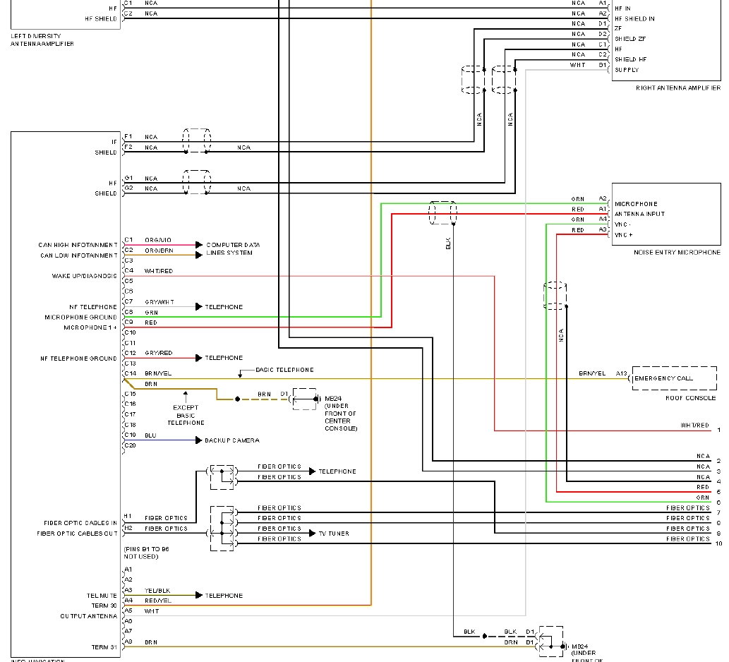
It appears the "Diversity" function wasn't part of the PCM. It was in one of the antenna amplifiers. See the diagram below:
Some explaining.. I believe there are a total of 4(!) antennas (not counting the GPS antenna) on the 955/957 Cayenne. Two FM frequency, and two AM frequency (referred to as HF and ZF or IF) antennas. The left amplifier takes the signals from 2 antennas, one in the side window rear and one in the rear window, amplifies them and sends them to the right side amplifier. The right side amplifier gets the signals from the left amplifier and it also adds in another rear window antenna and an antenna located in the spoiler. It does the "diversity" selection (selecting between the strongest signal) and then sends an AM and an FM signal to the PCM on separate cables.
This is why you NEED power to the amplifiers. Using the Y connector to connect the two antenna connectors at the rear of the new Android device is about as good as you can do since the Android device doesn't have separate HF and IF inputs. The advantage to having separate inputs for the two frequencies is that the input circuitry for the radio can be optimized for the widely different frequencies. It allows for greater selectivity, sensitivity, and better reception. Using a single input for AM and FM is actually common, and has been used for decades by vehicles without as complex an antenna system as the Cayenne has.
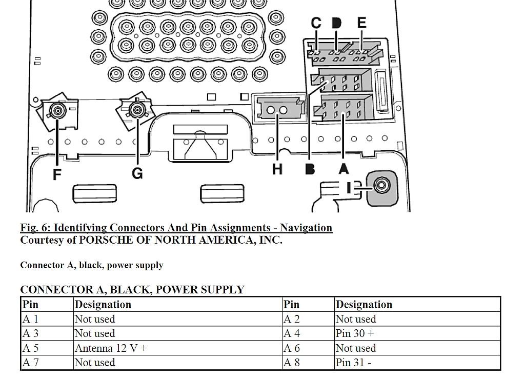
The important thing - the antenna amplifiers MUST be powered on. The diagrams indicate they were powered via the A5 (white) line from the original PCM. I believe you have to replicate this if you want decent radio reception.
Don, good stuff. Thanks for the extra explanation - - makes sense. I'll give that a shot when I've got a chance. My FM radio reception is mediocre as is.
Kraeburn,
I have the same unit, from the same vendor.
1. I have so far been unable to connect the unit to internet via my phone while on the road (wifi in the garage works great). I'm going to stop by Verizon today to try to confirm that this function is working correctly on my phone at-least.
2. Yes, same intermittant canbus error. It's only on the screen for a moment so it took me a while before I was able to read it, and I finally got a picture of it yesterday. The full message reads: "Developer warning for package "android.microntek.canbus" Failed to post notification on channel "null" See log for more details"
3. I tried to use my icarscan bluetooth OBD reader with Torque, it doesn't recognize it. I don't know at this point if it works with EZscan or not, I haven't installed it yet. Which OBD dongle is working with Torque for you?
4. Have not found a way to change temp readout, but since mine appears to say "-49.5c" which is -57F, not sure if it matters.
cheers,
c
I thought I should give a quick update about the canbus error. I finally spoke to the seller, I had been avoiding it, since I wanted to rule out as many things as possible first and there's a pretty strong language barrier. After some back and forth, they sent me new firmware to flash. It comes in two parts. To flash firmware, you copy the files onto a USB stick (despite the directions saying SD) and during the process, when the directions say to press any button, they mean the RESET button, which is the only mechanical button on my unit. It took some experimentation, but I got it all to update in about 30mins, error message now gone. It's been a couple of weeks since the update and I haven't noticed any other issues. YMMV.
With your correction - it sounds like it should work.
I opened it up over the weekend to see what the deal is. I removed the relay and with alligator clips connected it straight to the battery terminals; the SPDT relay itself functions as expected.
I then checked the reverse signal coming from the android harness and it turns out that wire is no longer providing 12V when the car is put in reverse. I assume this means that something burned within the android head unit because the wire itself looked okay.
I will either open up the head unit to peek around and/or I will have to wire to a different reverse signal (either route to reverse lights or hopefully somewhere much closer like the fuse box).
Let me see if I can find the antenna diagram... This shows A5 as being the power out going to the two antenna amplifiers.. you want this to go to a source switched by the new Android unit.
The android harness with RCA Audio Out that connects to MOST has a blue antenna wire on it. I verified that this blue wire is switched 12V and then plugged it into the blue wire coming out of fakra splitter. I now have some radio stations coming in! I will have to play with it more to determine if additional amplification is necessary.
BTW, the new firmware on mine allows picture-in-picture. If NAV is running, it superimposes a small map in the lower right over whatever is on-screen (videos, radio, etc.). The previous firmware didn't do this. Very cool.


 08-12-2018, 10:05 PM