When you click on links to various merchants on this site and make a purchase, this can result in this site earning a commission. Affiliate programs and affiliations include, but are not limited to, the eBay Partner Network.
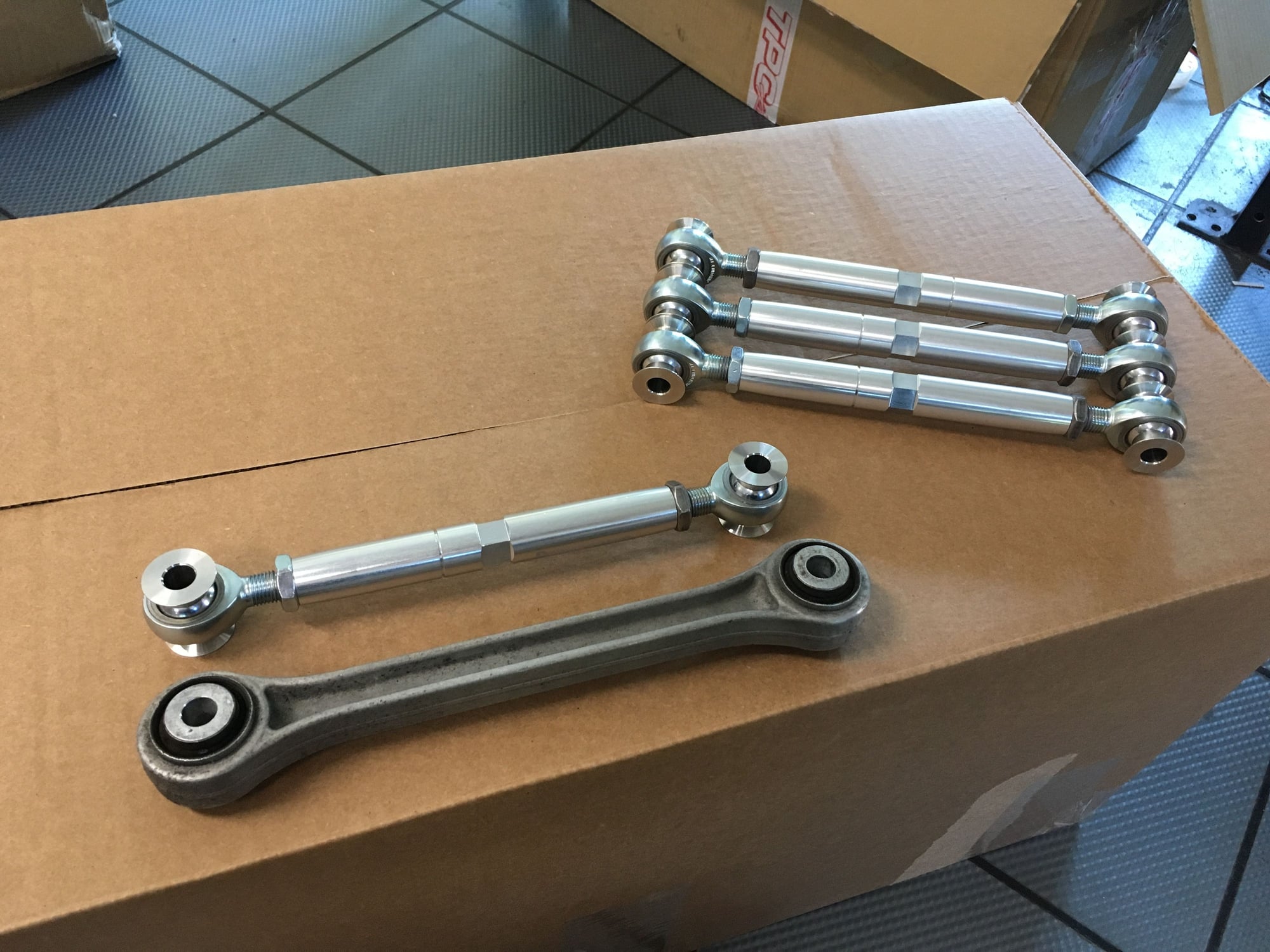
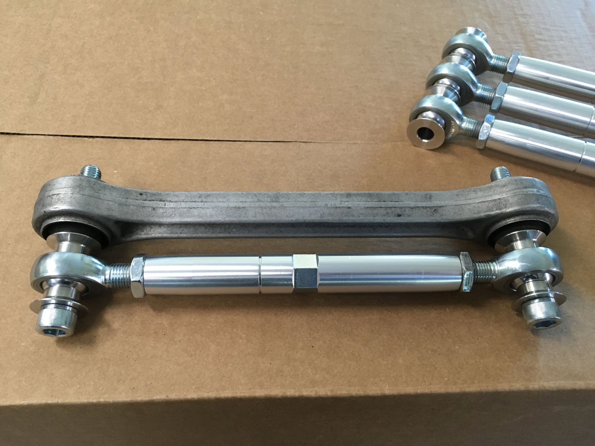
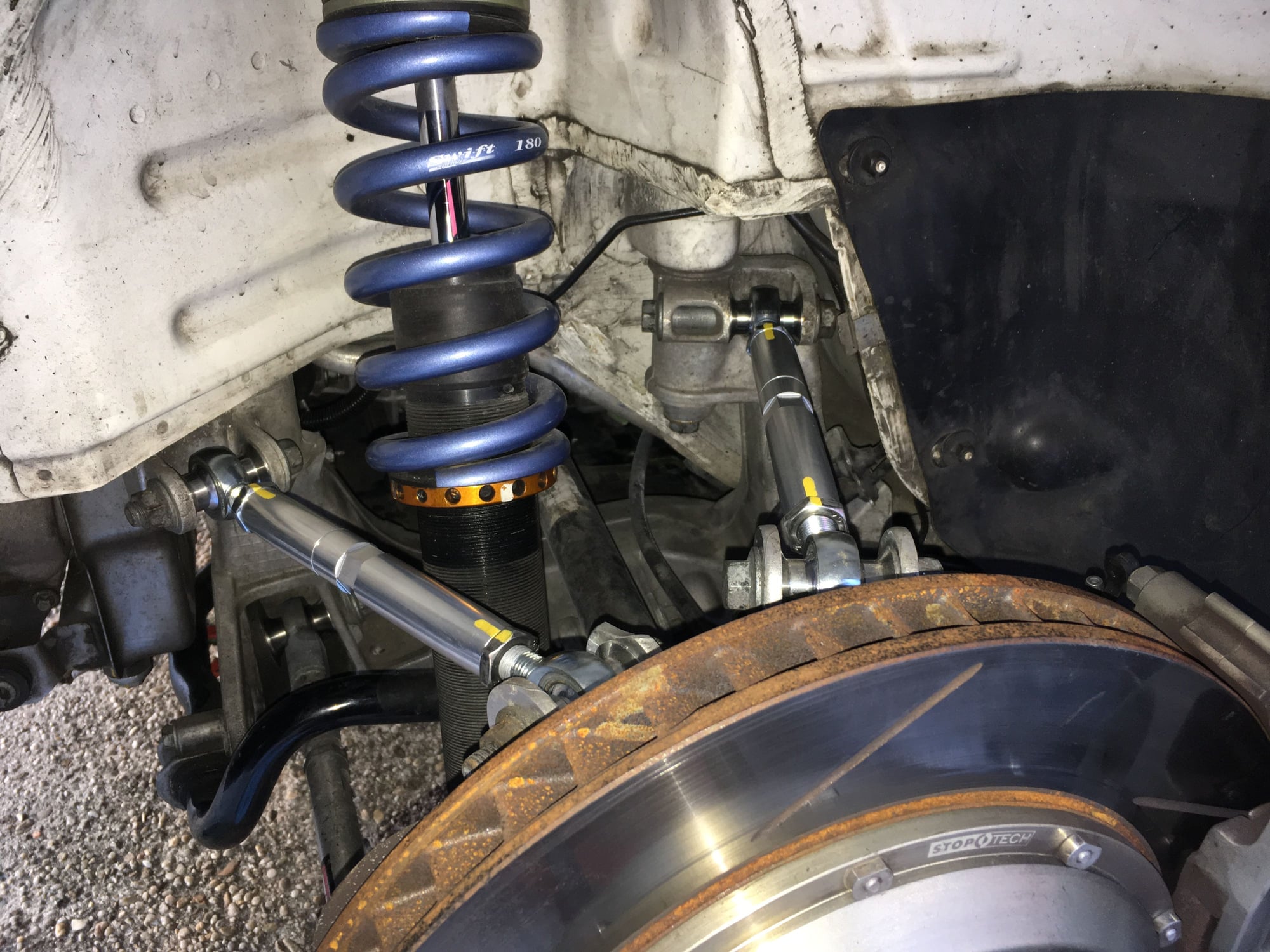
After doing the alignment and then swapping back to street wheels/tires(so I can drive home) I shook the wheels again just to be thorough. Then I noticed when the left rear wheel is shook in a particular way I feel a little bit of play from the suspension. This play doesn't feel like wheel bearing play nor toe link play. It seems to be from the upper portion of the wheel and have some rubbery resistance to the feel. Upper Links(aka Dog Bones)! I replaced the four Upper Links with 997.2 version 3 years ago, they have around 30 track days on them now. At that time, I had the thought in my mind that the .2 version was better than the .1 version only because they were factory equipped on the .2 RS, RS 4.0, and GT2RS road cars. Both version have the same non-adjustable I-beam shaped aluminum main structure with rubber bushings at both ends so I figured the .2 version has got to have stiffer rubber than .1, right?? It has been my observation that on my car and a number of customers cars(for track use) that the .1 version of the rubber bushings seem to be more durable when it comes to the "wheel shake test". Keep in mind that the wheel shake test cannot possible simulate even a fraction of the actual dynamic road/track forces applied to these parts so shaking the wheel is just a low-level test to find anything obvious. Another thought on the rubber bushings is that they do offer a small amount of camber gain during compression, which is a nice feature because the static camber can be set lower (by like 0.2 to 0.3 deg) for straight line and braking and then have the gain during corner loading. As nice as the dynamic camber gain feature sounds, I think its time to graduate from rubber to monoball Upper Links like the .1 Cup to .2 Car did.
Here's a set of Upper Links from Ed @ Demon Speed Motorsports. Because of DSM's reputation, and because I am drawn to the natural aluminum color of the links.
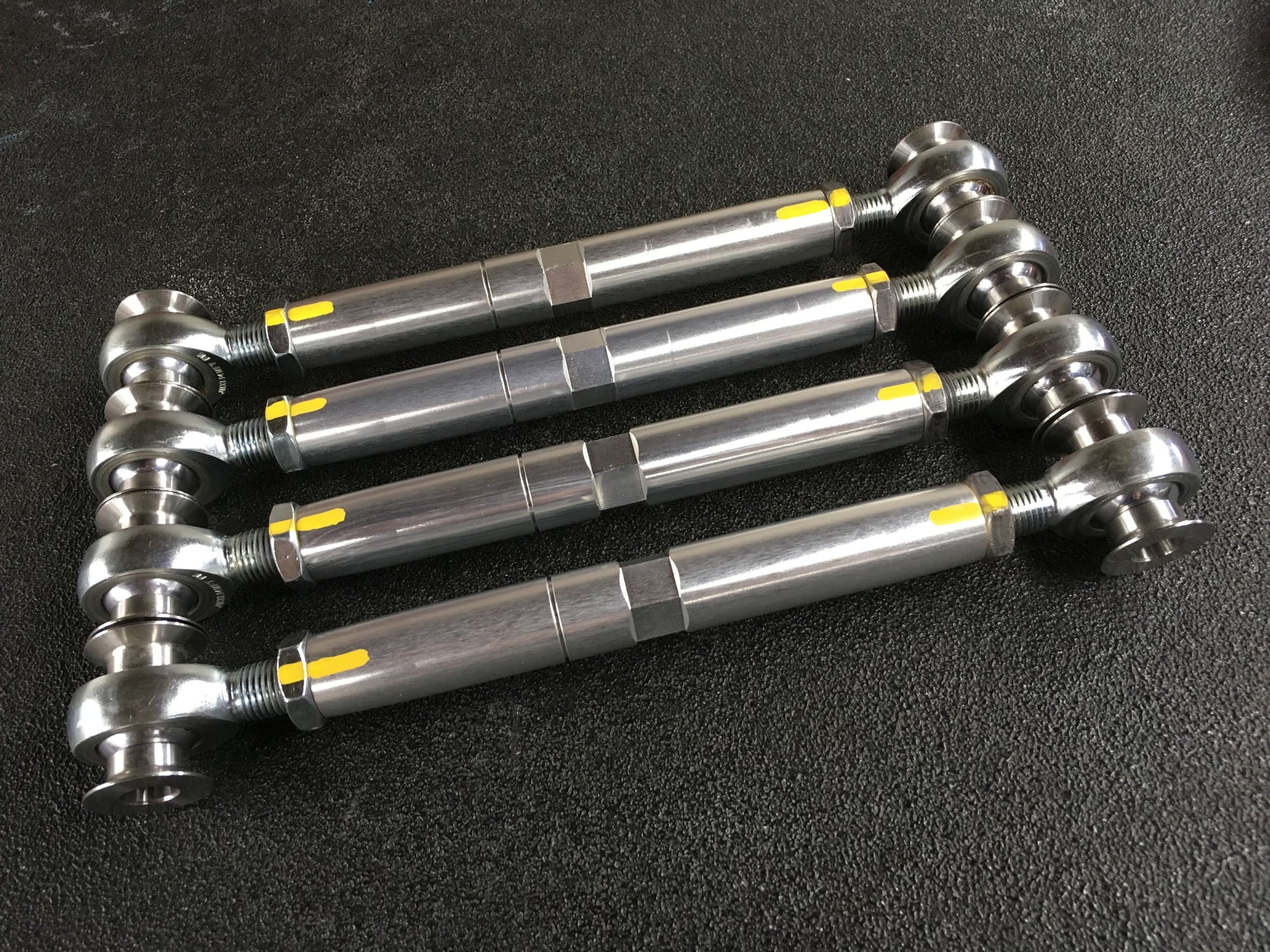
Using a good OEM Upper Link as a fixture, I set the monoball links to the same static length as the OEM rubber bushing links. This way the static rear camber should be the same. But I'll check and see.
All set, locked, and paint marked.
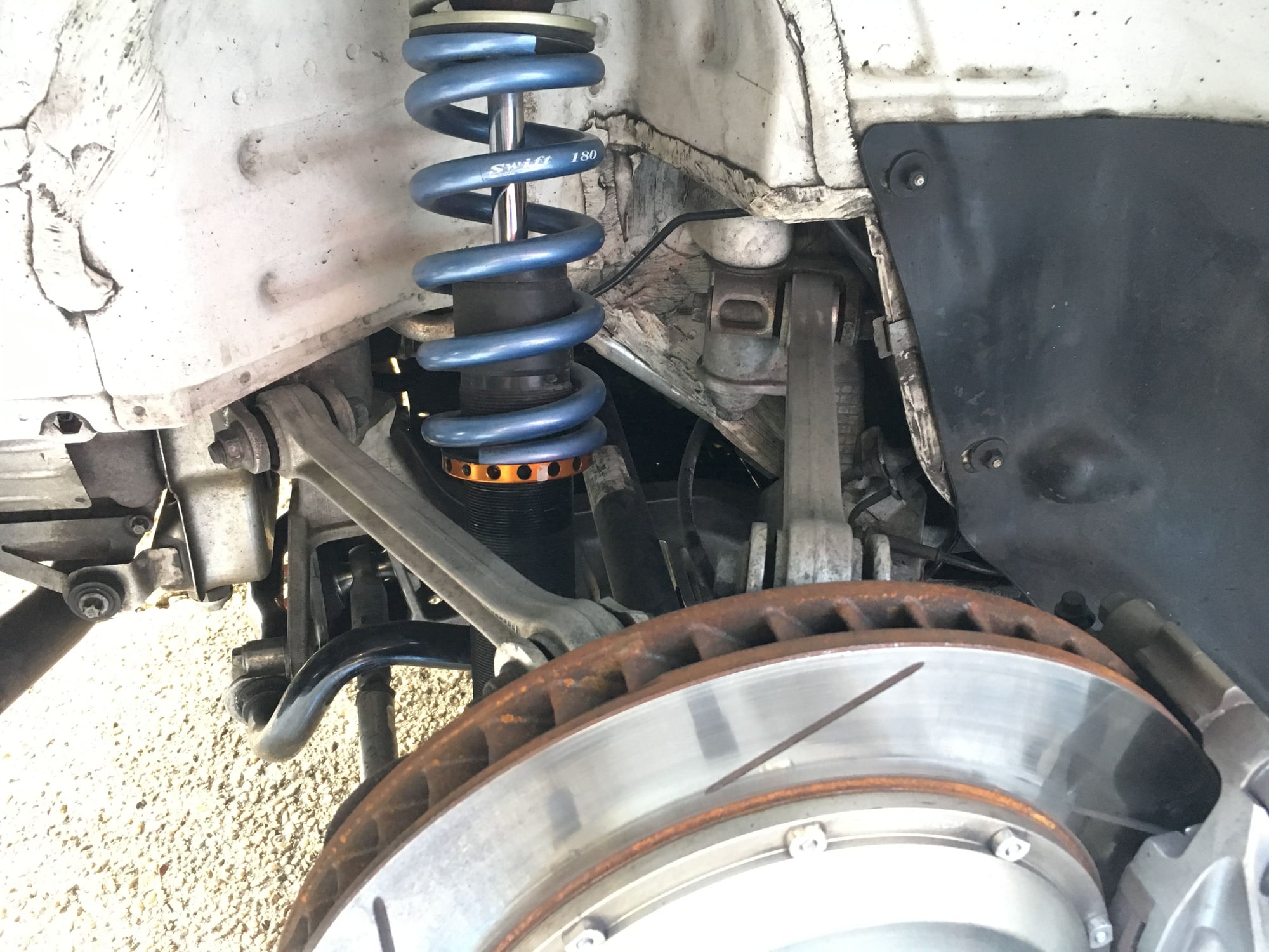
Before...
After..
First drive on street feels good so far. Depending on how the rear camber looks it may need a small tweak. Always something with these cars...LOL
__________________
PCA National Instructor
TPC Racing stats:
2023 Porsche Sprint Challenge 992 Cup Am Champion
2023 Porsche Sprint Challenge GT4 Pro-Am Team Champion
2022 Porsche Sprint Challenge 992 Cup & 991 Cup Champion
2020 IMSA GT3 Cup Challenge 2nd Championship
2018 IMSA GT3 Cup Challenge 2nd Championship
2016 IMSA GT3 Cup Challenge Champion
2013 IMSA GT3 Cup Challenge Champion
2006 Rolex-24 @ Daytona GT Champion
2004 Grand-Am SGS Class Champion
In addition, I have yet to really understand what adjusting these does. I guess you can move the track a bit - within the limits of the CV joints as long as you keep the relative positions the same...
Nop. They were installed as is right out of the box. I'll report on back on durability after some track use.
Originally Posted by rbahr
In addition, I have yet to really understand what adjusting these does. I guess you can move the track a bit - within the limits of the CV joints as long as you keep the relative positions the same...
People adjust them for various reasons; some use Upper Links length adjustment to lessen rear negative camber, some for rear wheel to quarter panel clearance(by a few millimeters), some to widen rear track width along with widening LCA's (like you said, within the limit of CV joints, I think safe range is probably up to 7mm per side). For high-performance usage, a length change of the Upper Links should be followed by a bump steer test and make bump steer adjustment as needed.
Car looks great Tom! What were the final alignment numbers? I recently set my car set up for for 275/645-18 and 315/680-18 Pirellis on 18x10x12.5 wheels. I initially set the camber at -3.5F and -3.0R and after testing this past weekend it's not nearly enough as the outer shoulders get punished even with significantly stiffer springs than yours. Camber will need to be about -4.00F and -3.5R at a minimum if the car is gonna get driven..
My concern with adjusting these is that you are introducing a complex motion, not a simple inclination in a particular plane. That makes imagining what this actually does a bit more complex. I have looked for some affordable modeling packages for this suspension, but have yet to find one...
Car looks great Tom! What were the final alignment numbers? I recently set my car set up for for 275/645-18 and 315/680-18 Pirellis on 18x10x12.5 wheels. I initially set the camber at -3.5F and -3.0R and after testing this past weekend it's not nearly enough as the outer shoulders get punished even with significantly stiffer springs than yours. Camber will need to be about -4.00F and -3.5R at a minimum if the car is gonna get driven..
you're correct on the alignment needs for the Pirelli's, I'm at -3.7 and -3.2 and it's not enough.
side note, your car has to be bonkers on those tires!
My concern with adjusting these is that you are introducing a complex motion, not a simple inclination in a particular plane. That makes imagining what this actually does a bit more complex. I have looked for some affordable modeling packages for this suspension, but have yet to find one...
Ray
A valid concern indeed. That's precisely why I set my upper links to OEM length. Otherwise I'd have to send hours...days...testing and adjusting bump steer.
What were the final alignment numbers? I recently set my car set up for for 275/645-18 and 315/680-18 Pirellis on 18x10x12.5 wheels. I initially set the camber at -3.5F and -3.0R and after testing this past weekend it's not nearly enough as the outer shoulders get punished even with significantly stiffer springs than yours. Camber will need to be about -4.00F and -3.5R at a minimum if the car is gonna get driven..
Originally Posted by AudiOn19s
you're correct on the alignment needs for the Pirelli's, I'm at -3.7 and -3.2 and it's not enough.
side note, your car has to be bonkers on those tires!
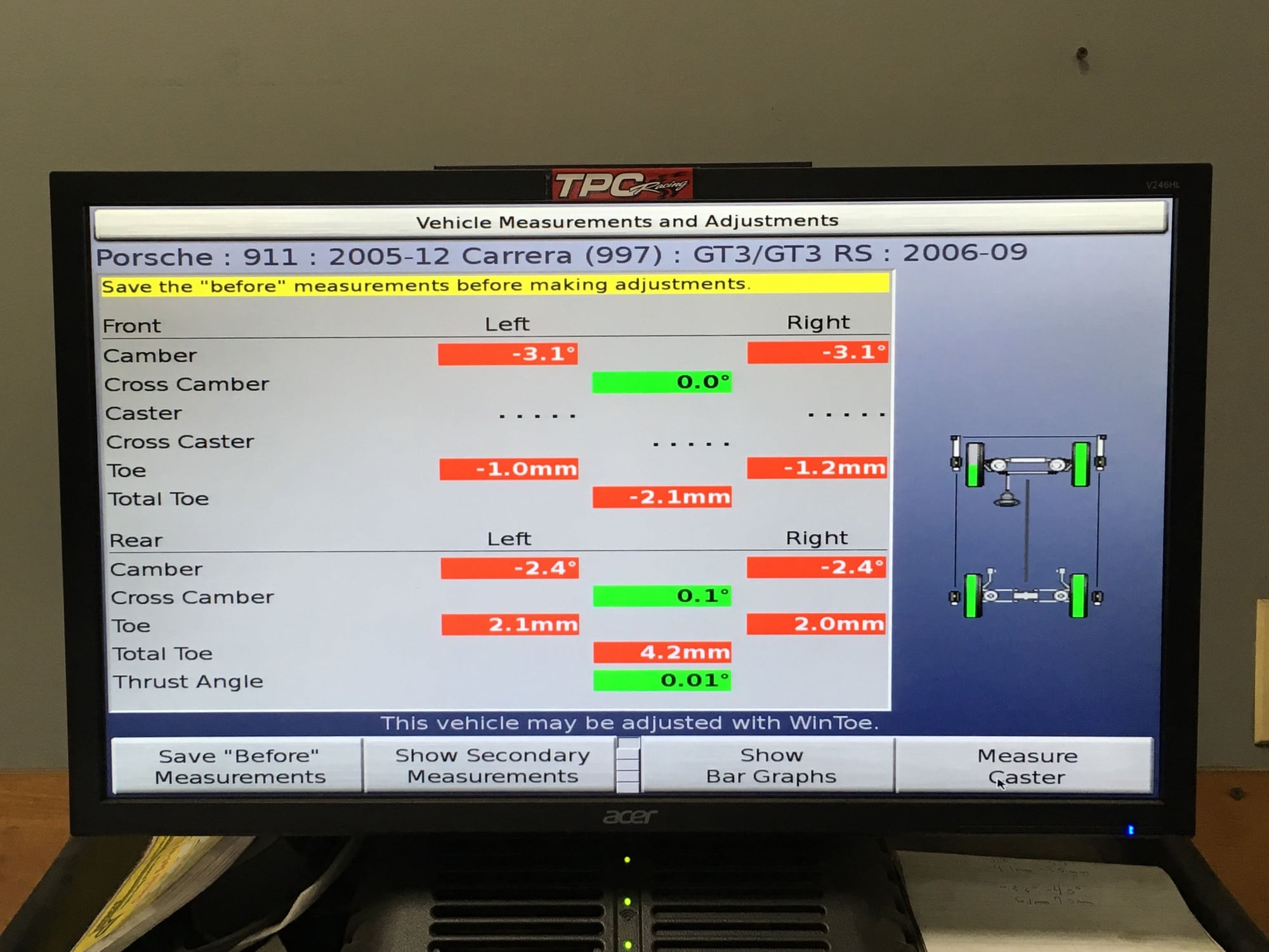
The TPC Racing team has decades of setup experience running slicks on race cars, but I have zero personal experience running slicks on a street car. Majority of my non-racing track day/HPDE customers run R-comp tires, and some of them switch to Cup cars and slicks. With that said, and with some info gathering from quick drivers whom I respect, there's basically two different camps on camber for slicks from the info that I gathered. On one camp is Cup car level camber like you guys are running, Thank You Very Much for sharing the info! In the other camp is milder level camber that's closer for R-comp. I don't know the reason why the more aggressive camber works better for some drivers while the milder camber works better of other drivers. Perhaps I can find the reason(s) after gaining some personal experience. I suspect it has to do with car setup, features of the track, and driving style... Currently I'm running milder camber(-3.1 F and -2.4 R) because I'll be switching between slicks and R-comps as a transitional phase. Thanks gain for the info!
The TPC Racing team has decades of setup experience running slicks on race cars, but I have zero personal experience running slicks on a street car. Majority of my non-racing track day/HPDE customers run R-comp tires, and some of them switch to Cup cars and slicks. With that said, and with some info gathering from quick drivers whom I respect, there's basically two different camps on camber for slicks from the info that I gathered. On one camp is Cup car level camber like you guys are running, Thank You Very Much for sharing the info! In the other camp is milder level camber that's closer for R-comp. I don't know the reason why the more aggressive camber works better for some drivers while the milder camber works better of other drivers. Perhaps I can find the reason(s) after gaining some personal experience. I suspect it has to do with car setup, features of the track, and driving style...
Just thought of something that answered my own question. Softer suspension setup car will have more camber gain during peak load thus needing less static camber relative to stiffer suspension setup. For example lowering the car's ride height by 10mm will gain approx 0.5 degree negative camber so therefore if the suspension is soft enough to compress 10mm during braking or cornering then the same amount of camber is gained.
you're correct on the alignment needs for the Pirelli's, I'm at -3.7 and -3.2 and it's not enough.
side note, your car has to be bonkers on those tires!
Hey Andy,
Yeah, the car is a monster. Chris Cervelli and I were at the track last Friday doing the initial suspension set up runs and the car feels amazingly composed and easy to drive. He is a true magician at setting up the suspensions on these cars. We are going to tweak a few items and bump the camber to -4.25F and -3.75R but overall we are about 80% of the way there. He also built the engine and gearbox on the car this past winter and both are phenomenal. Here are few laps Chris turned on the second session out and ran a 1:48 which at HPR is a blistering pace that has only been touched by a local modified 4L 997.2 GTA2 Cup and few 997RSRs in the past. Very few street GT3s will get below the 2.00 min mark which is normally the bench mark there that most strive to get under.
Thanks for sharing your video. A Monster indeed! Chris Cervelli is among the top race car builder/technician in the country. I had the honor of working with him once in a Grand Am Cup race at PIR some years back.
This is completely superficial but wanted this so here it is-
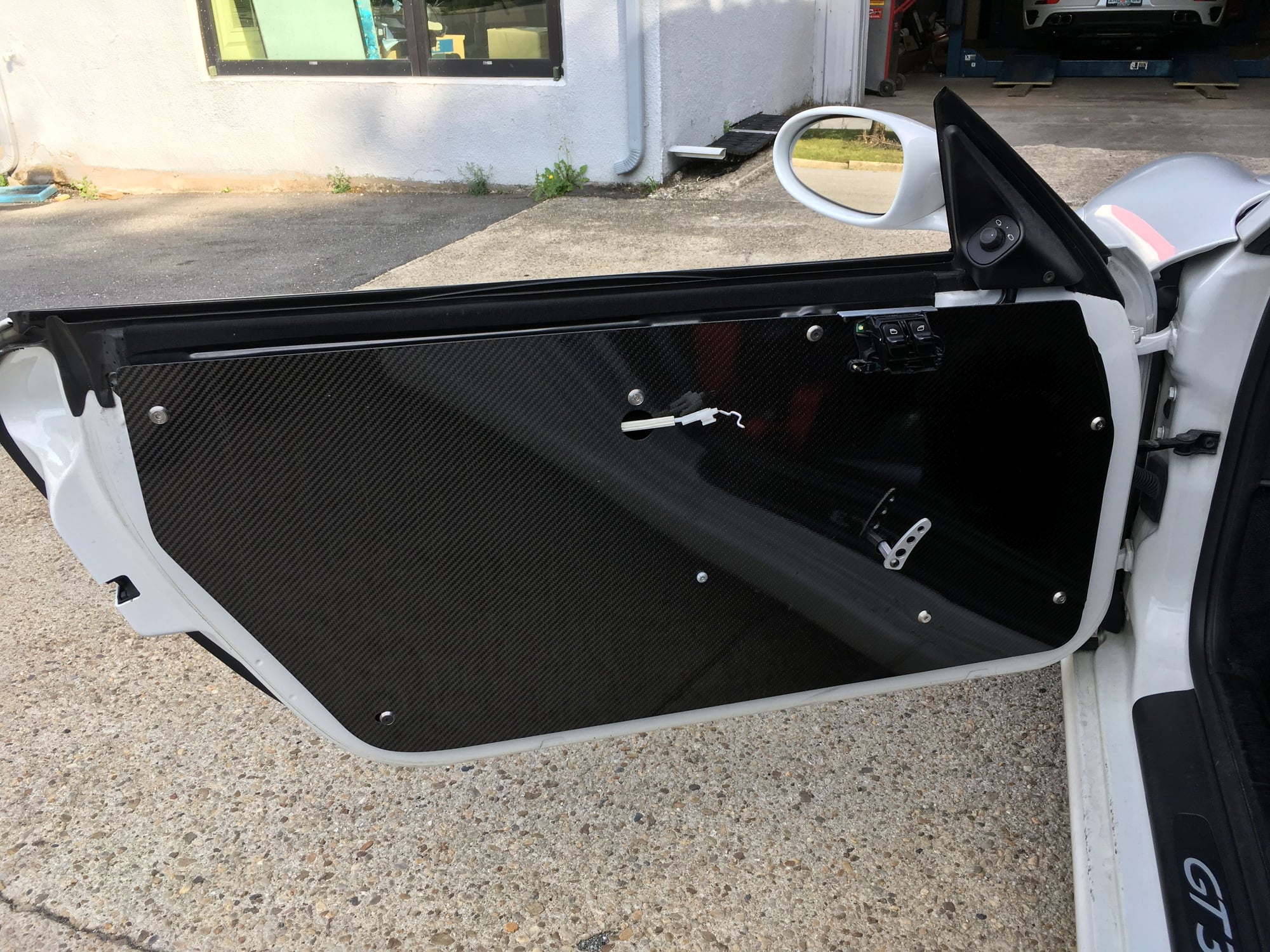
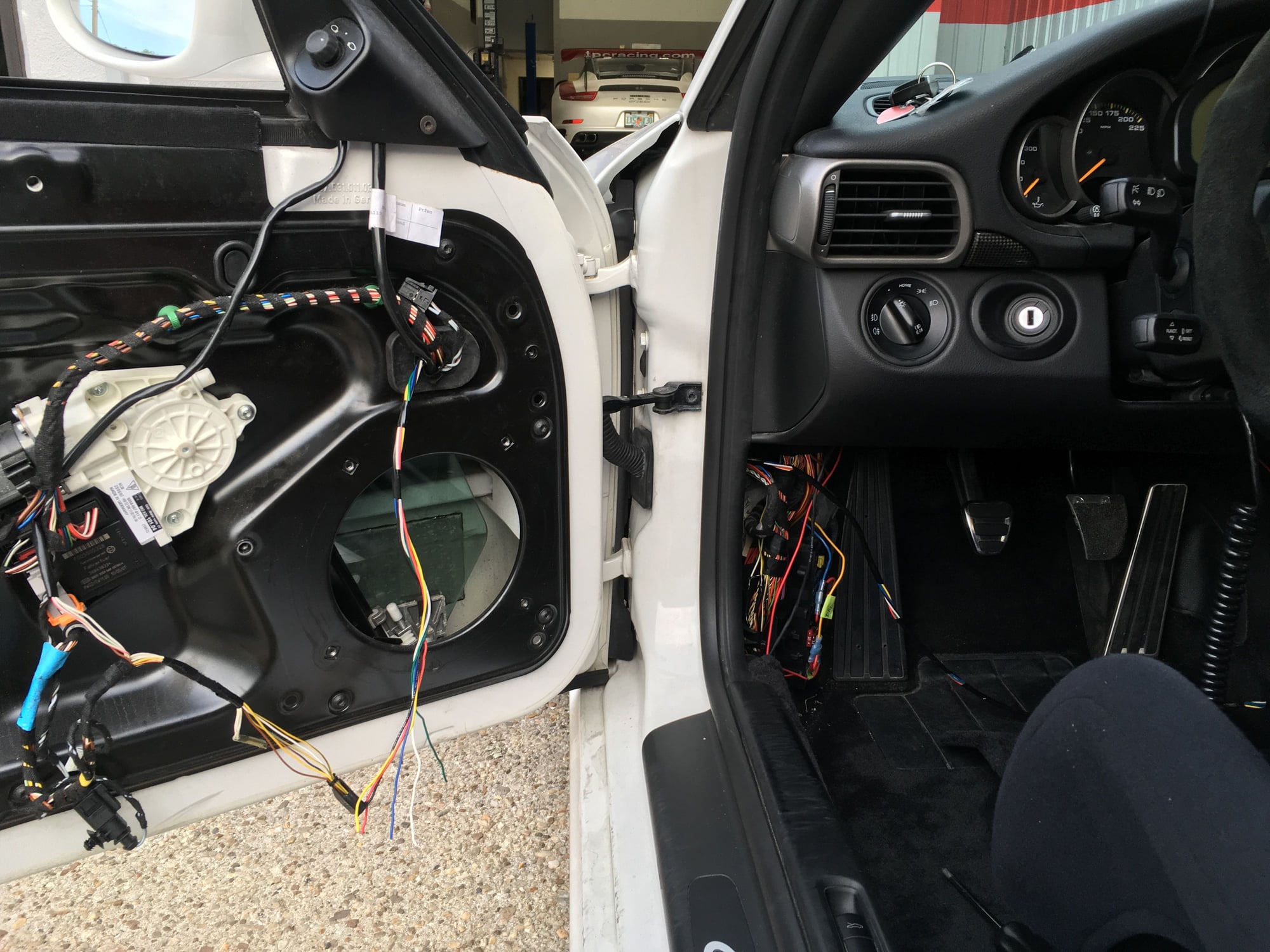
I was never satisfied with how I mounted the power window switches when I deleted the OEM door panels 2 year ago. The switches were mounted in a rush on a parking lot...in the rain. Since the driver side switch has been intermittently faulty and needs to be replaced, now is a good opportunity to do a better job.
Previously I cut out a slot on the carbon fiber sheet and crudely made a upper support to keep the switch held in the slot. It worked, but the switch assembly flexes as the carbon fiber sheet does.
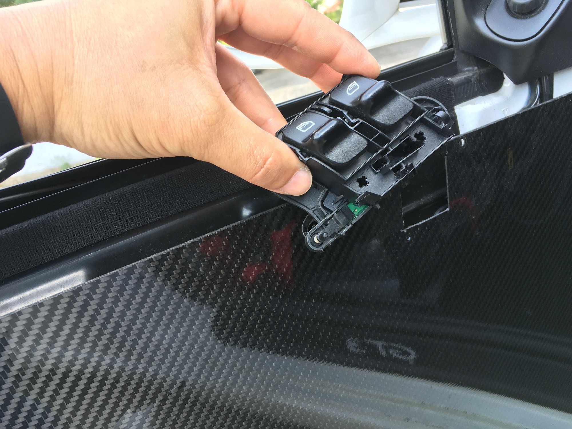
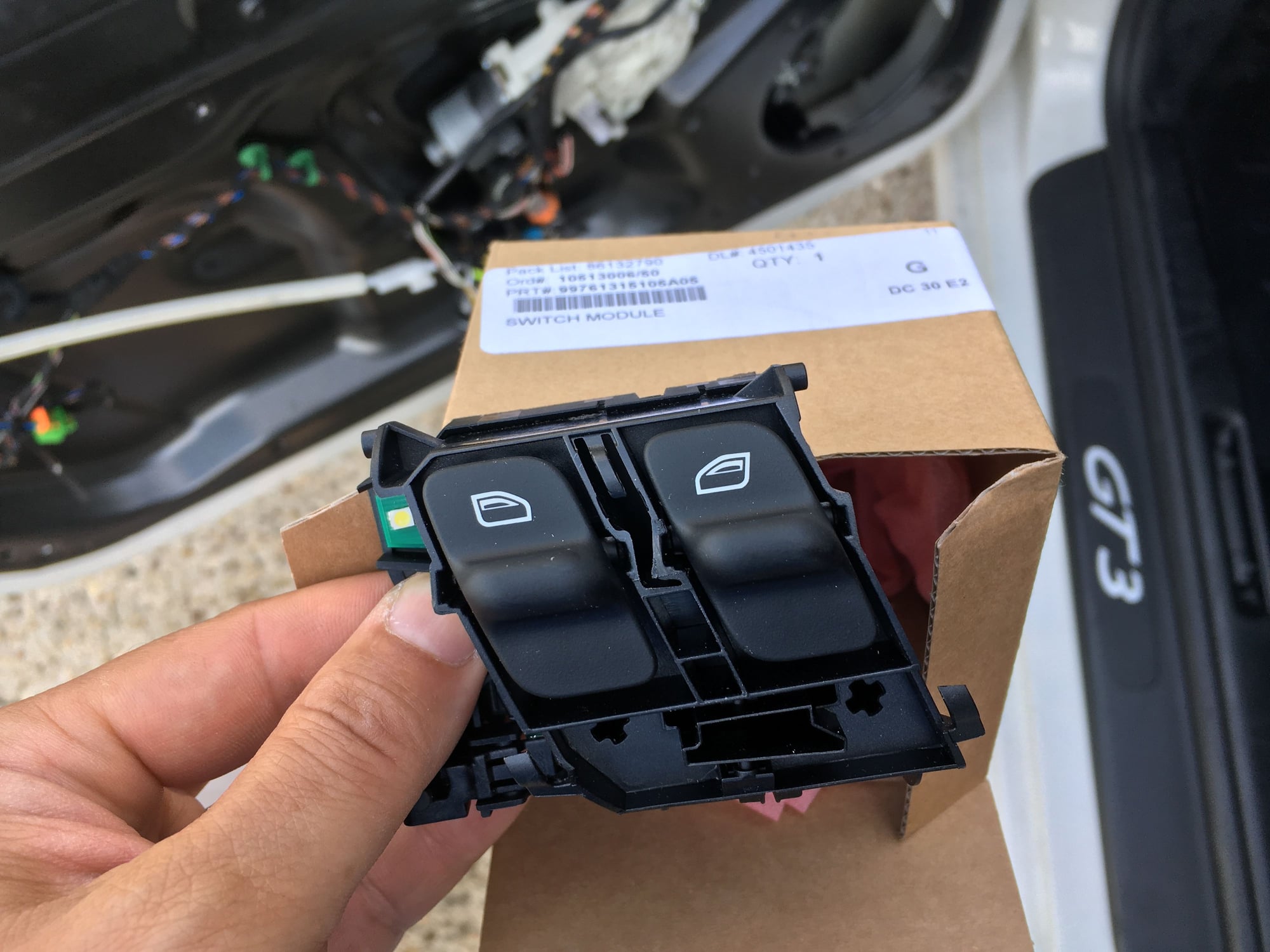
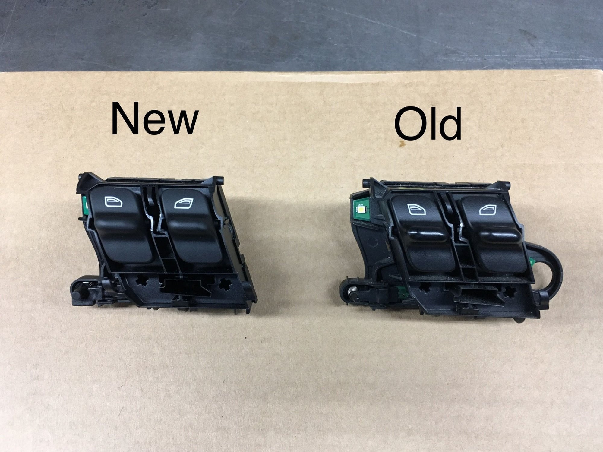
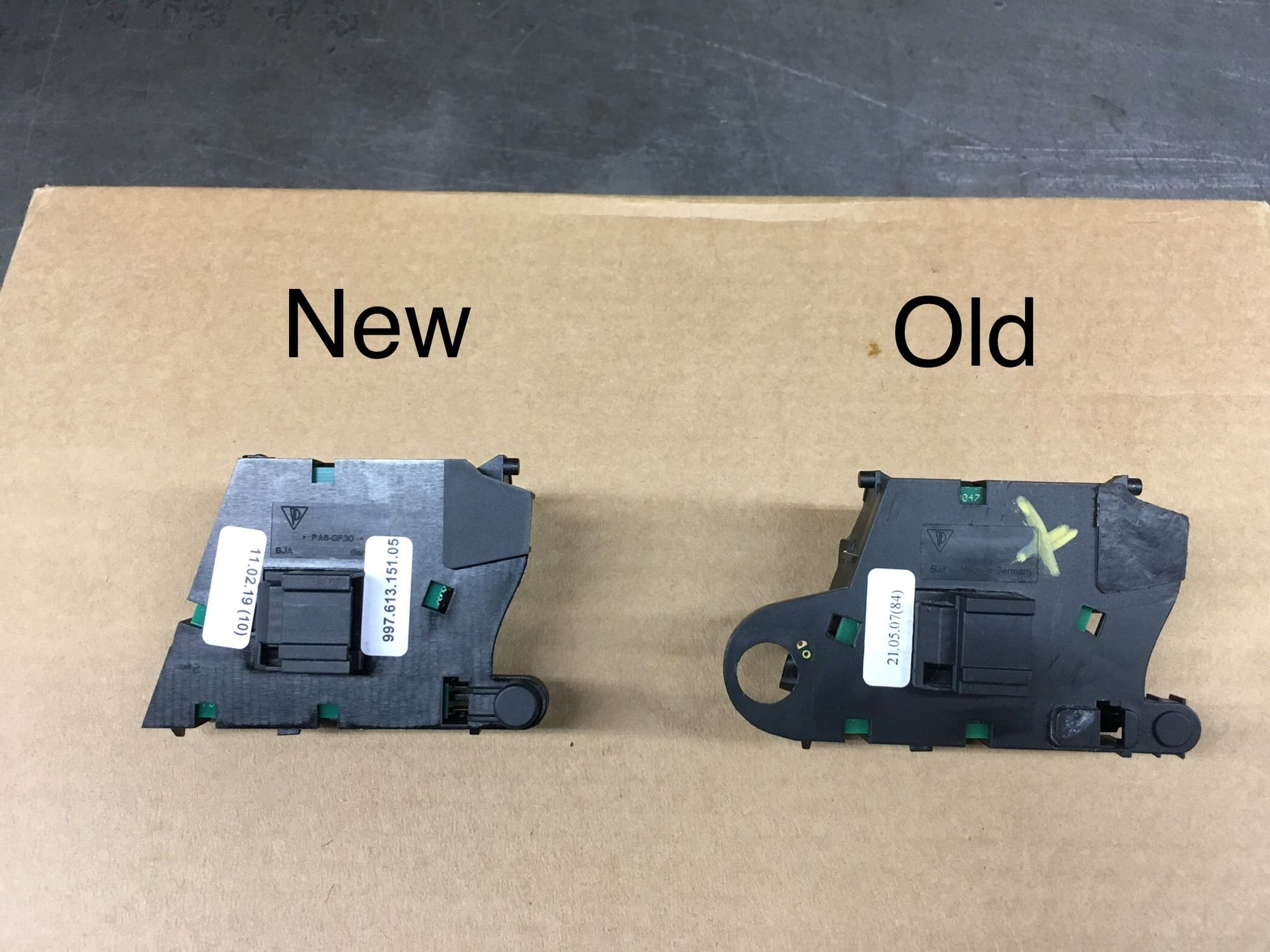
New switch. The part # has been superseded. Looks like a better grade of plastic.
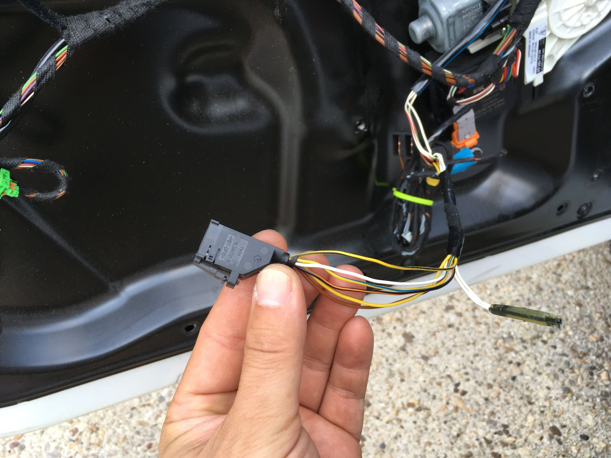
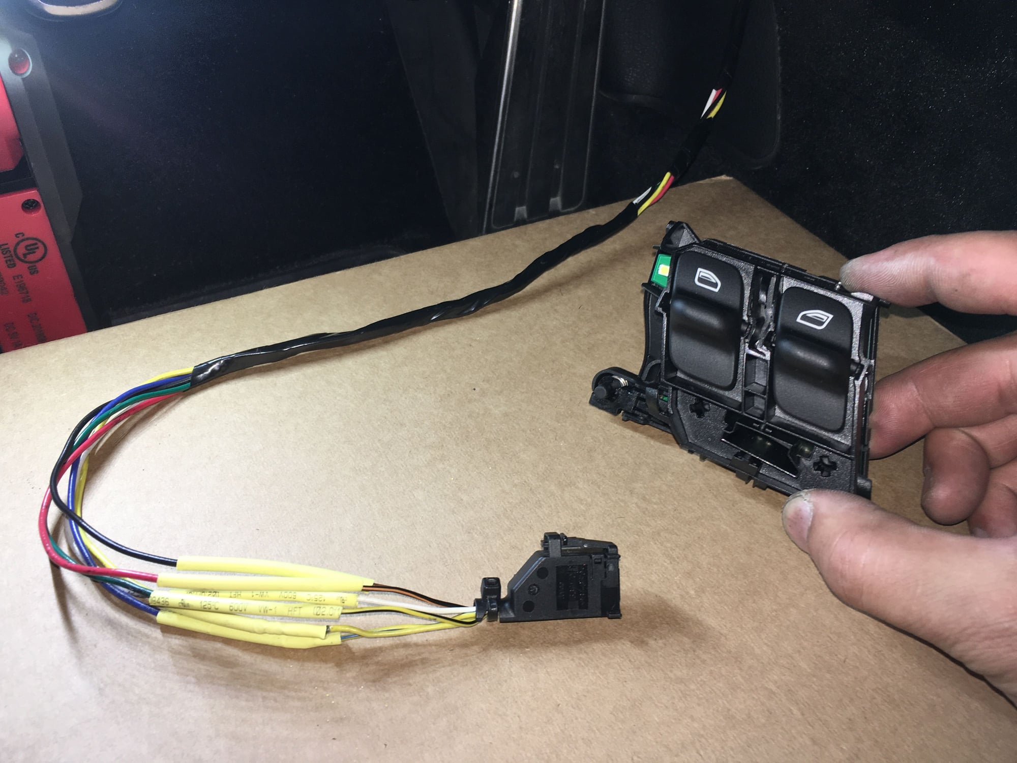
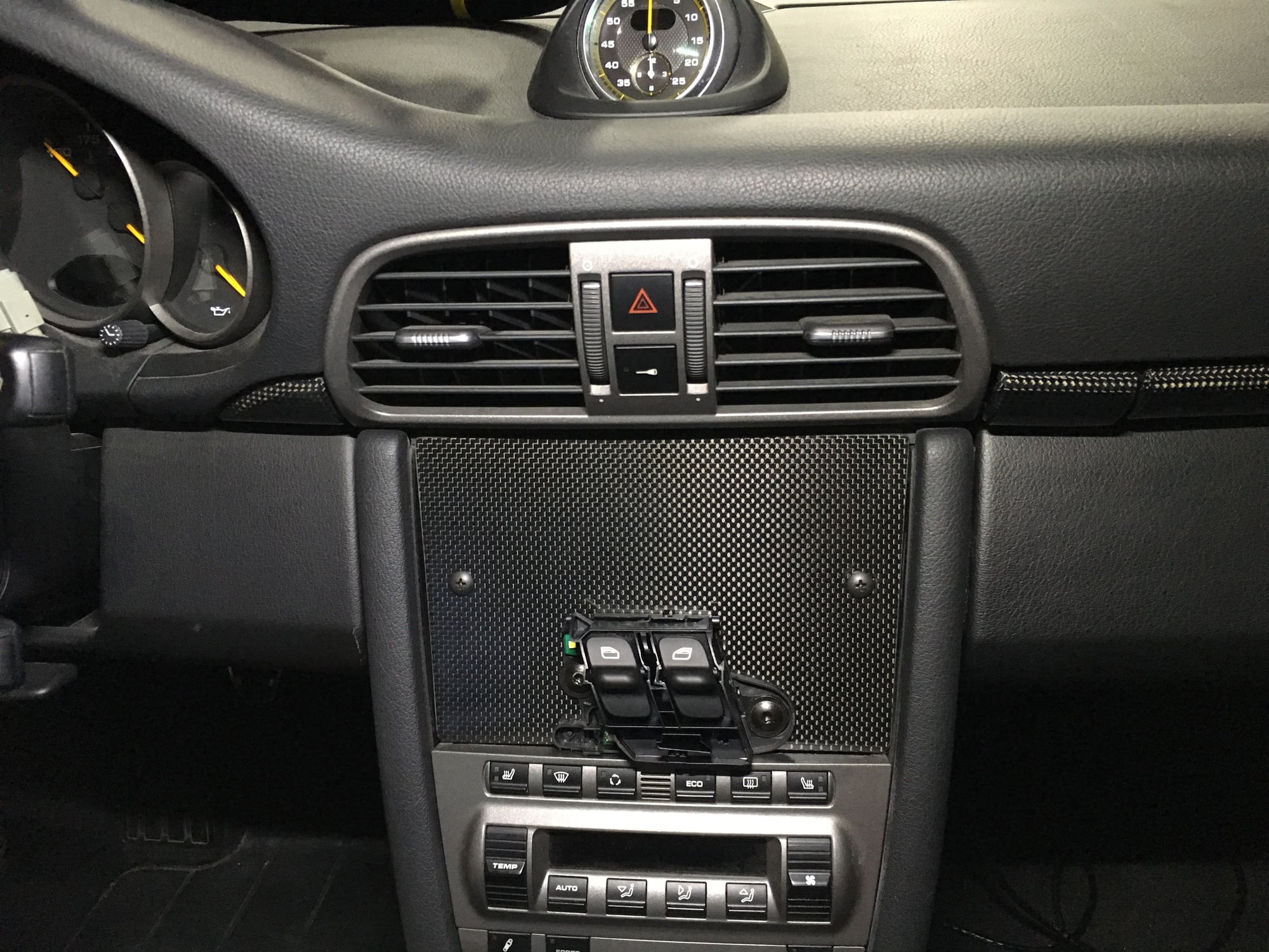
Okay, so my idea of "better" is relocating the driver side switch assembly to the middle of the car and deleting the passenger side switch. Here's the 6-wire connector for the switch.
Let the wiring begin.
The most PITA part of the job is feeding the 6-wire loom through the door, then into the flex tube, then into the cabin. I started at 6pm with excellent daylight, finished feeding through at 8pm just starting to get dark! Time to bring out the flash lights.
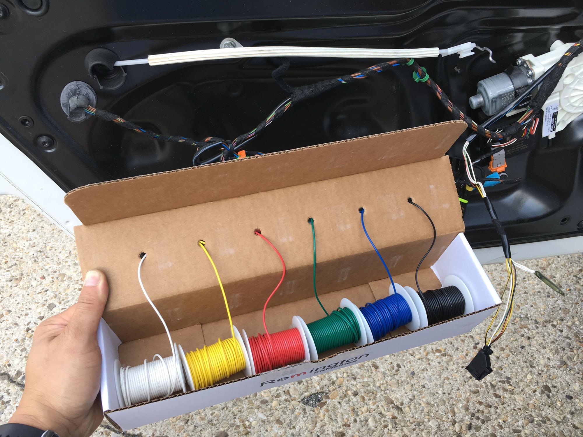
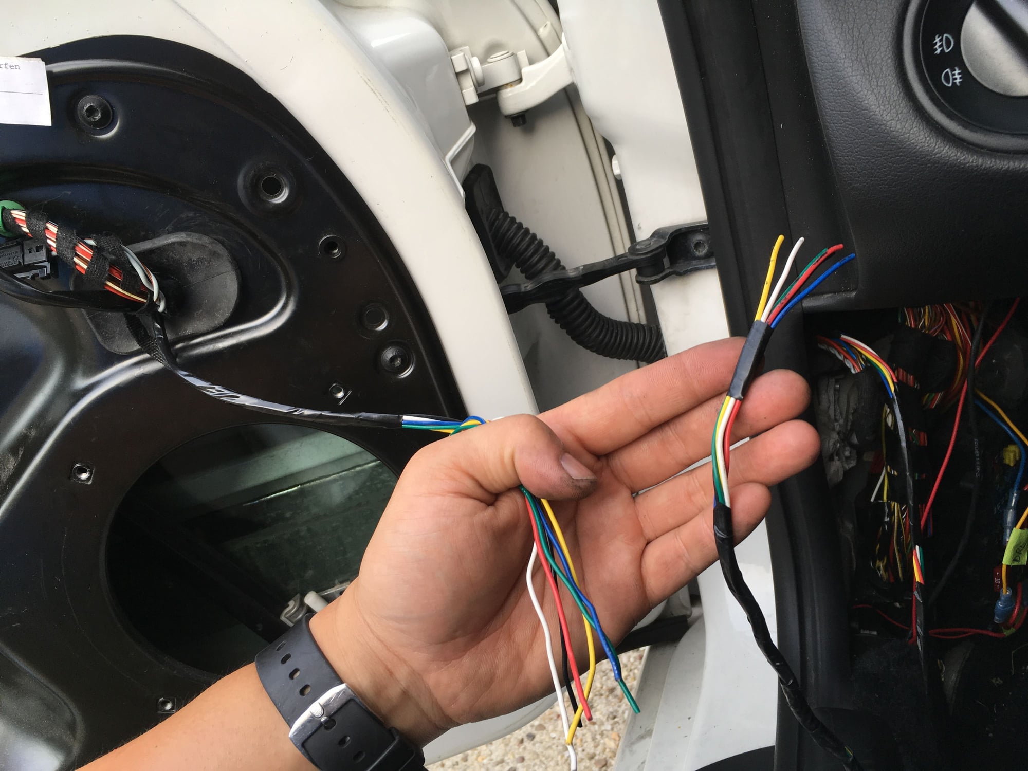
Wires, wires...
Testing the new switch before soldering.
Soldered and shrink tube'd.
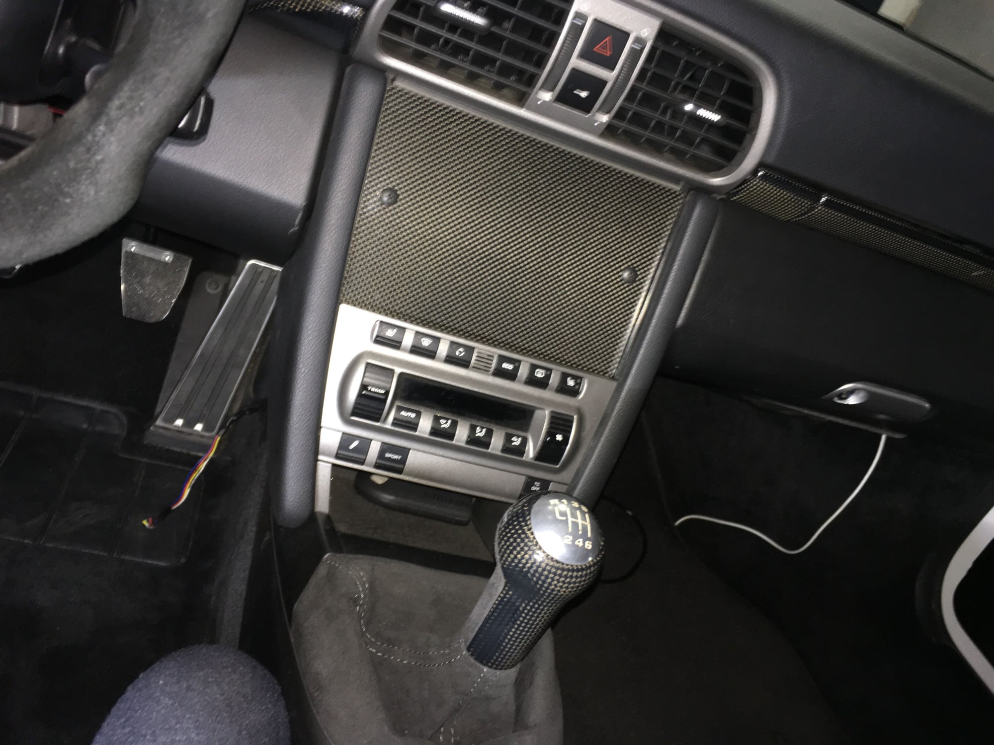
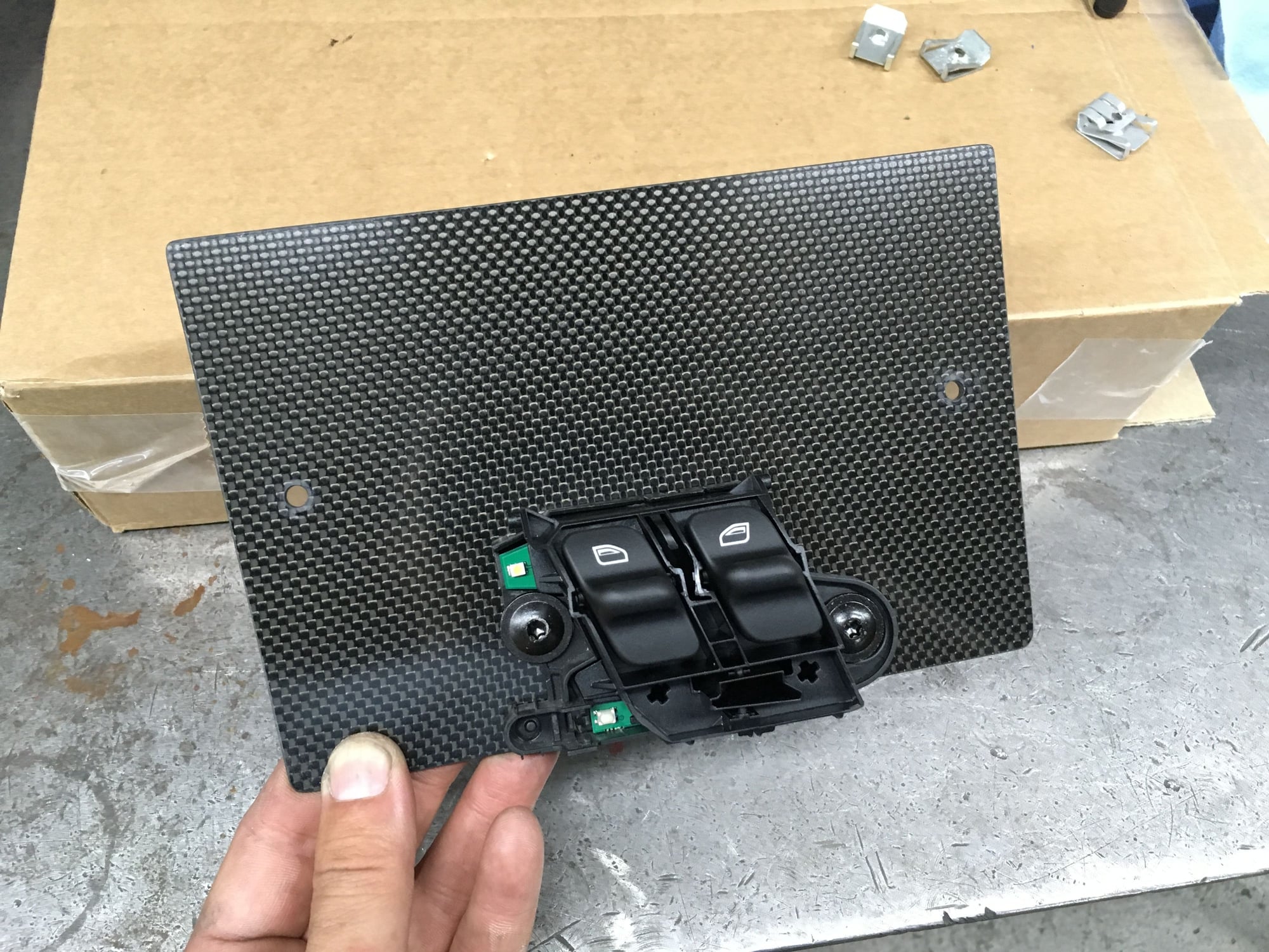
I did the radio delete 2 year ago. Replaced the radio with a carbon fiber plate with intent to put buttons and/or switches on the plate. Perfect for the window switch.
Encountered a little snag at 10pm. That is the superseded(new) part number switch doesn't have the extra material at the base for mounting!
I need that extra tab for mounting. Dammit.
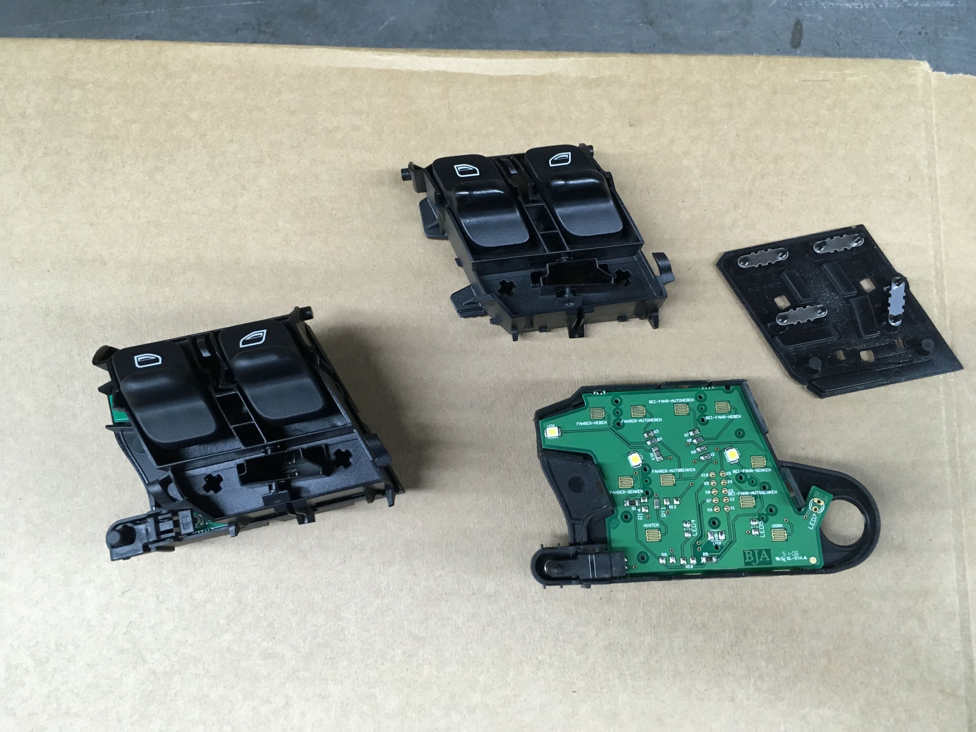
Taking apart the switches and carefully modifying the fragile plastic base(measuring, drilling, grinding). Basically making one usable switch from two.
Two hours later.
The switch is relocated, tested, it works, and very stable. I started at 6pm and finished at 2:05am. Have to come back to work by 7:30am. Strangely, I don't feel tired, perhaps its because I am Very Satisfied.
Last edited by Tom@TPC Racing; 06-26-2019 at 10:00 AM.
Love it! If you dont mind me asking where did you get the door panels? Looks great!
Originally Posted by Tom-TPC Racing
This completely superficial but wanted it so here it is-
I was never satisfied with how I mounted the power window switches when I deleted the OEM door panels 2 year ago. The switches were mounted in a rush on a parking lot...in the rain. Since the driver side switch has been intermittently faulty and needs to be replaced, now it a good opportunity to do a better job.
Previously I cut out a slot on the carbon fiber sheet and crudely made a upper support to keep the switch held in the slot. It worked, but the switch assembly flexes as the carbon fiber sheet does.
New switch. The part # has been superseded. Looks like a better grade of plastic.
Okay, so my ideal of "better" is relocating the driver side switch assembly to the middle of the car and deleting the passenger side switch. Here's the 6-wire connector for the switch.
Let the wiring begin.
The most PITA part of the job is feeding the 6-wire loom through the door, then into the flex tube, then into the cabin. I started at 6pm with excellent daylight, finished feeding through at 8pm just starting to get dark! Time to bring out the flash lights.
Wires, wires...
Testing the new switch before soldering.
Soldered and shrink tube'd.
I did radio delete 2 year ago. Replaced the radio with a carbon fiber plate with intent to put buttons and/or switches on the plate. Perfect.
Encountered a little snag at 10pm. That is the superseded(new) part number switch doesn't have the extra material at the base for mounting!
I need that extra tab for mounting. Dammit.
Taking apart the switches and carefully modifying the fragile plastic base(measuring, drilling, grinding). Basically making one usable switch from two.
Two hours later.
The switch is relocated, it works, and very stable. I started at 6pm and finished at 2:05am. Have to come back to work by 7:30am. Strangely, I don't feel tired, perhaps its because I am Very Satisfied.
Love it! If you dont mind me asking where did you get the door panels? Looks great!
Thanks!
The door panels were cut from generic sheets of carbon fiber. These are 1mm sheets for paneling that doesn't require structural support.
I did this 2 years ago, see post # 697 in this thread. Here's the short cut- https://rennlist.com/forums/997-gt2-...07-gt3-47.html

 06-24-2019, 11:12 AM