When you click on links to various merchants on this site and make a purchase, this can result in this site earning a commission. Affiliate programs and affiliations include, but are not limited to, the eBay Partner Network.
Post project note: I've added a table of contents to this opening post as a convenience to those that may stumble across this later. However, anyone reading this should not ignore all the other posts in the thread. There is a ton of great information others have contributed.
After living with the rather agreeable ride of Bilstein B6 (HD) and M033 springs on my 140k mile Targa for the past few years, I wanted better handling out of the car, more in the spirit of someone doing real track time, but still very comfortable on the street.
After discussing my specific usage model with Steve Weiner, he recommended a few changes - one of those being PSS10s.
While I'm waiting for them to arrive, I thought I'd start a thread showing the step-by-step process of installing these things. I don't think this is necessarily a very advanced DIY, but questions on the installation do come up regularly. Hopefully yet another suspension thread will add some value to the community.
This morning, I decided to start with the easy part - removing the right front strut assembly.
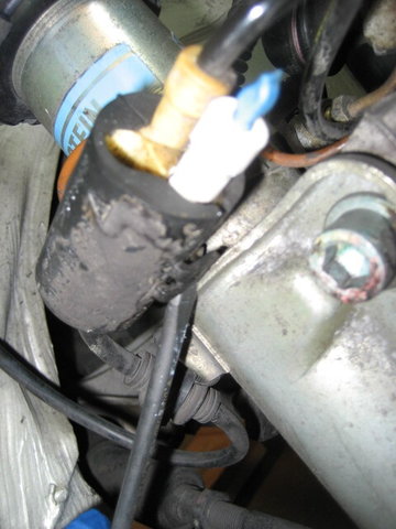
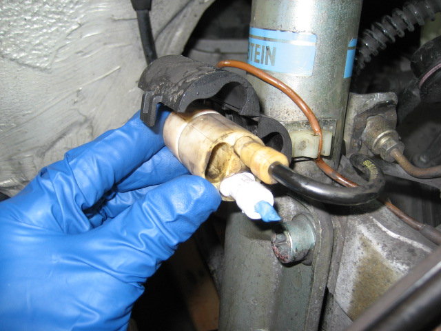
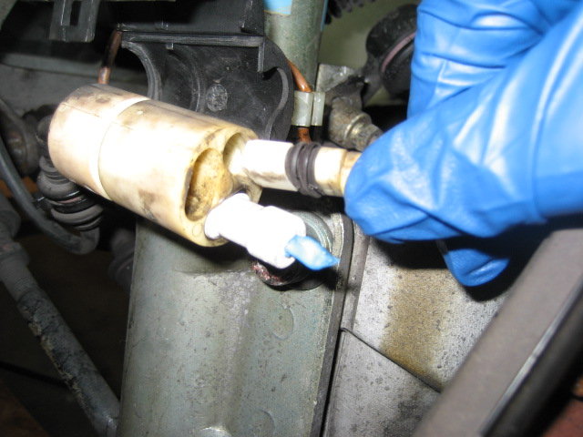
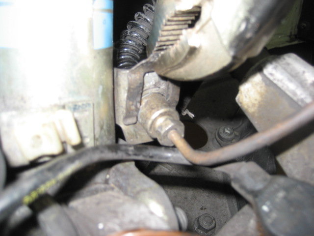
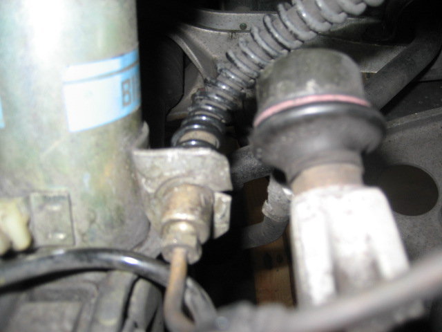
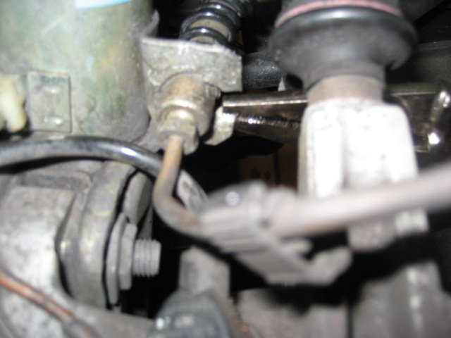
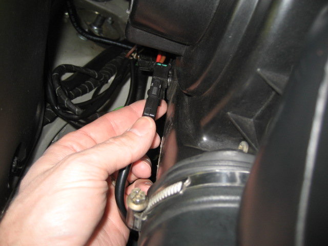
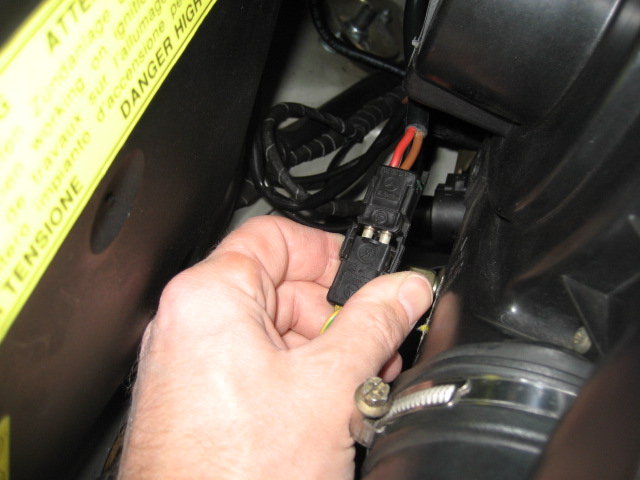
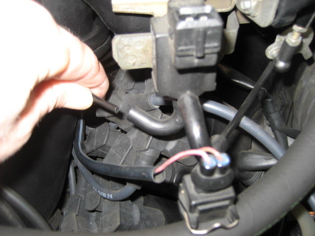
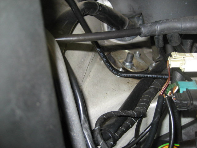
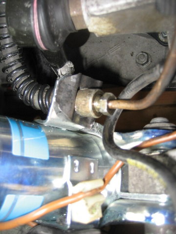
After getting the car in the air and removing the wheel, I opened the connector unit on the strut and disconnected the RPM sensor. I didn't disconnect the brake pad sensor, because I obviously am not using pad sensors at the moment.
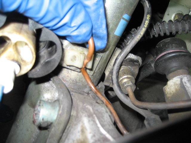
Next I removed the ground cable from its clip.
I must have not had the clip to attach the harness to the strut when I replaced the Monroes last time and used some wire ties instead. I clipped one of the ties to free the harness from the strut.
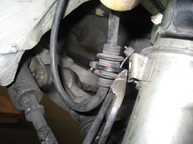
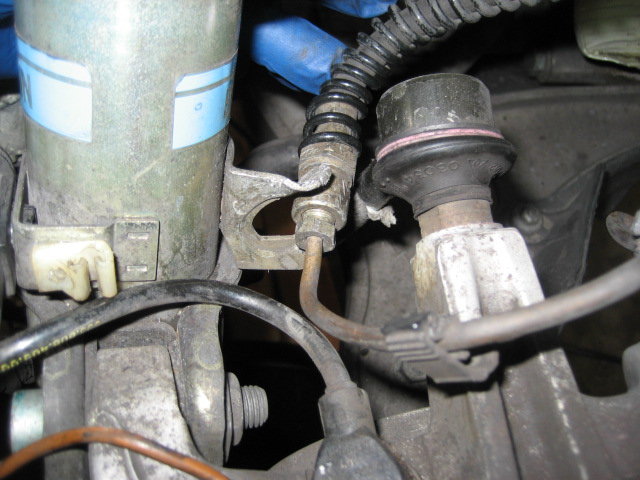
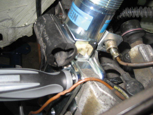
One of the more controversial parts of replacing struts is whether to separate the brake lines or cut the strut mount. The last time I did this, I obviously cut the strut mount. This time, I'll likely separate the brake line because I like to do things properly
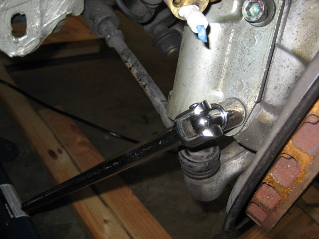
After removing the brake line clip, I bent the mounting point out of the way and removed the brake line from the strut.
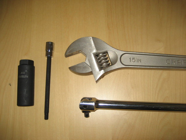
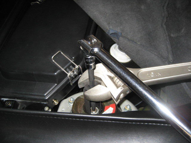
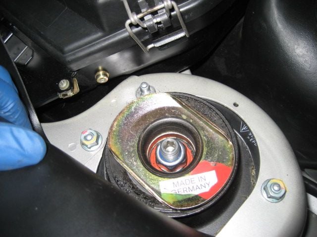
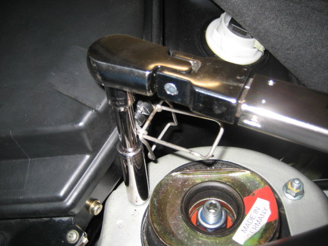
I assembled the tools to loosen the top fastening nut on the strut shaft. These tools made this a 5 second job.
*7/8 O2 sensor socket from Harbor Freight
*7mm long hex bit socket
*3/8 breaker bar
*Gigantic adjustable wrench
I then loosened, but did not remove the top nut. I'll remove the nut once the new PSS10s arrive.
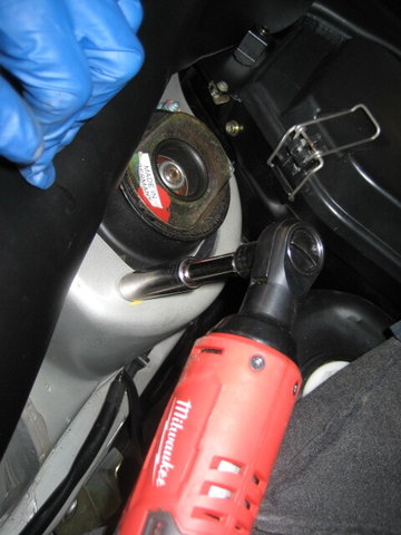
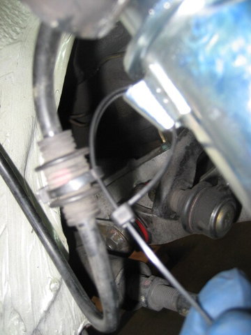
Next, I removed the fasteners that hold the strut to the wheel carrier. These were very snug and needed my largest breaker bar to remove.
It was much easier to loosen (but not yet remove) the 4 13mm nuts that hold the strut assembly to the body. My cordless ratchet made this a breeze.
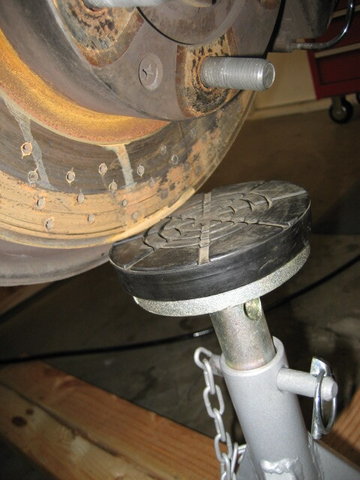
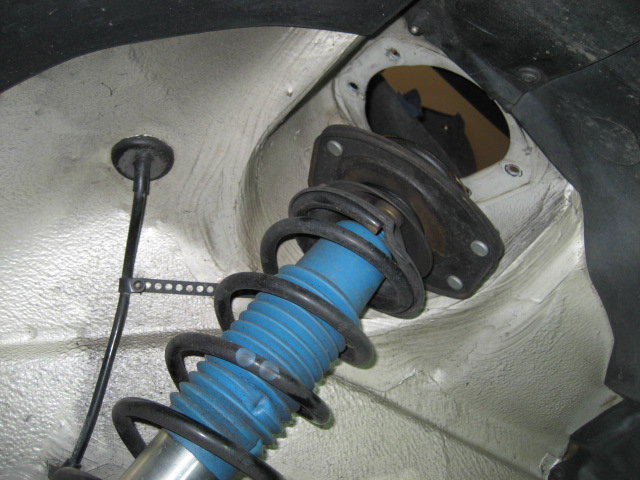
Before removing the strut, I positioned a jack stand under the rotor to support the suspension once I removed the strut. Ignore the rust on the rotor - I just washed the car before starting this project.
Once supported, I freed the wheel carrier from the strut by just wiggling it free.
I then held the strut with one hand under the car, while using my electric ratchet on top of the car to remove the remaining fasteners holding the strut in place. Once removed, I carefully lowered the strut assembly and removed it from the car.
So far it has been a very easy process. I can't wait to get started on the back struts, because that's when the fun begins
Last edited by mpruden; 01-16-2017 at 09:45 PM.
Reason: Added table of contents
Thanks mpruden.
Watching this thread for tips for my replacement in the not too distant future, its a job that I've been too scared to do since I bought the car.
Since the box from UPS hasn't yet arrived, I decided to get a jump start on the rear of the car by getting the air box and aux fan assemblies out of the way. This probably isn't technically required to get the rear struts out, but it does improve clearance greatly.
I can't count the number of times I've removed these assemblies. It probably takes me 5 minutes for each one, although with all the pictures, it looks more involved than it really is.
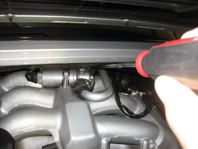
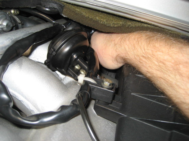
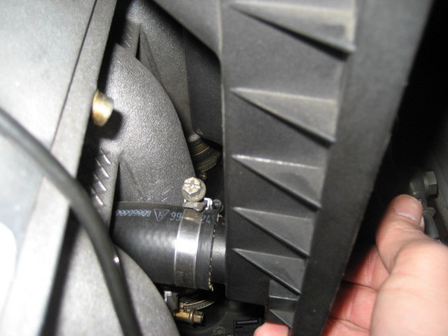
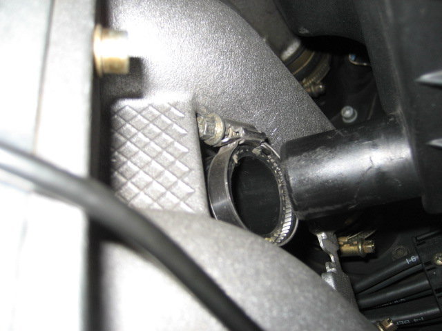
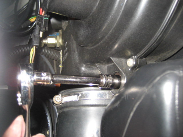
I got started on the air box by loosening the secret hose clamp well hidden behind the ISV and it's various hoses and wires. I used a very long flat head screwdriver for this. I just needed to loosen it a few turns.
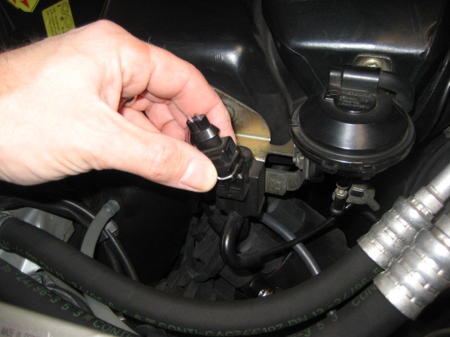
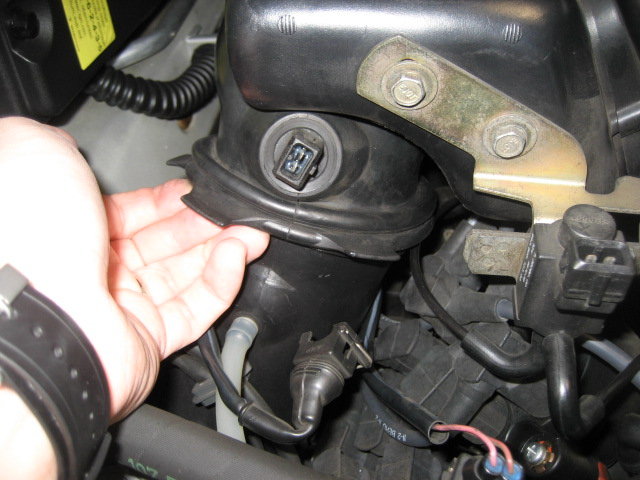
Next, I grabbed the MAF wiring connector and rotated it toward the front of the car until it stopped, about 15 degrees or so.
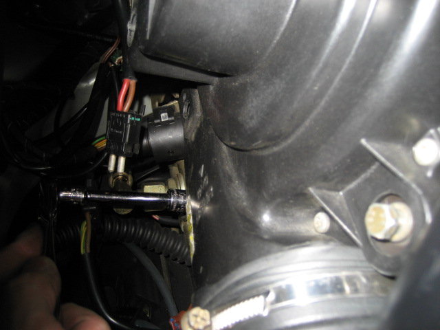
Here's what it looked like after I rotated it forward. Once rotated, it is now unlocked from the air box.
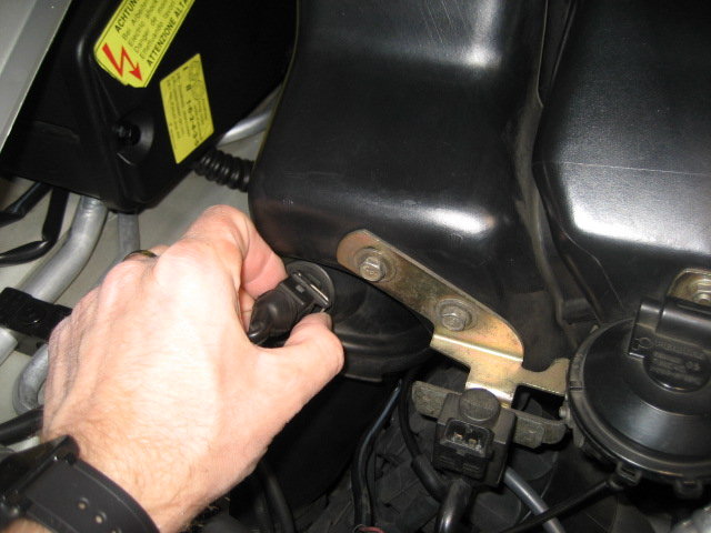
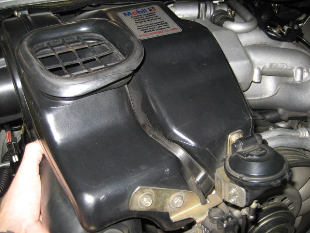
I then removed the air box cover by detaching the clutch vent hose, unfastening the two cover clips, and lifting the cover out of the car.
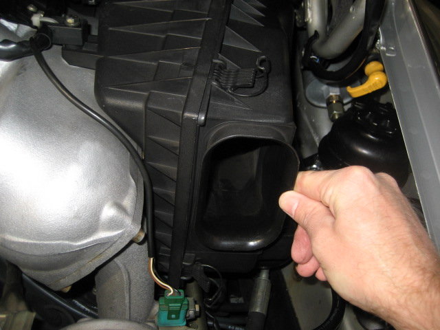
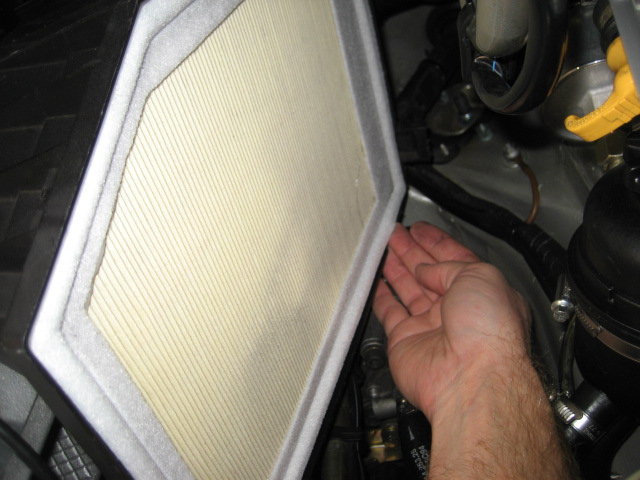
I removed the air filter using the handy notch Porsche designed into the bottom of the air box for this reason.
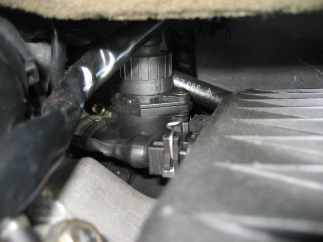
Next I disconnected the electrical cable from the intake air sensor and removed the fastener that goes through the wiring harness, air box, and into the varioram.
I then lifted the cover up and out just enough to loosen this last hose clamp and disconnect the hose from the air box.
I was then able to lift the air box up and out of the car.
Boom - plenty of room now.
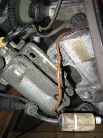
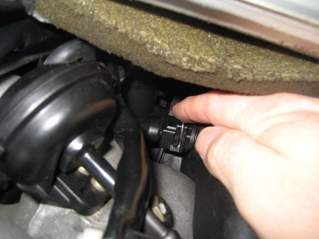
Next, I moved to the left side of the engine compartment and removed the three electrical connectors on the aux fan assembly. Note that the fan power cable is snapped into the assembly and may not be immediately visible.
I've found it's easiest to next separate the soft rubber sections that make up the air egress and ingress points from the rest of the car. I just used my fingers for this. It's easy.
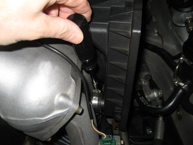
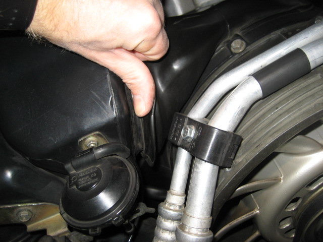
One single vacuum hose was next. This is the only one you have to disconnect on my '97 varioram car.
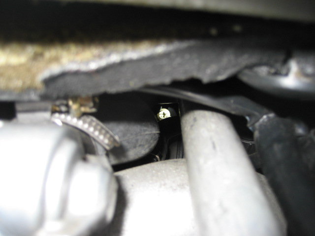
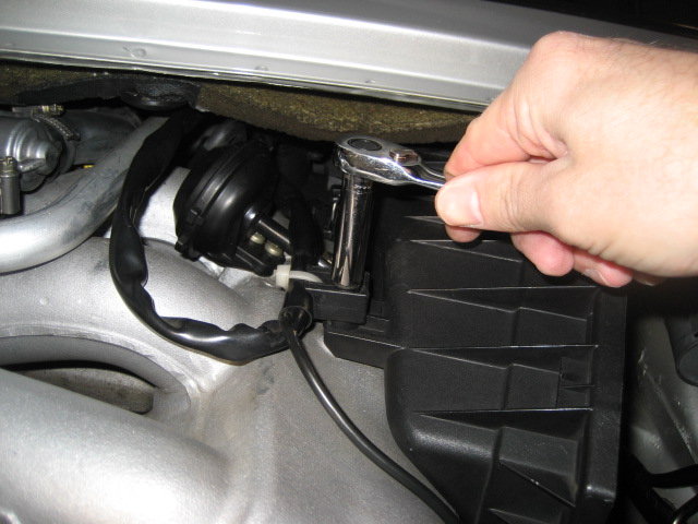
Last, I undid the two screws that hold the assembly to the varioram. One is easy to see, the other not so much.
Once removed, I lifted the aux fan assembly up and out of the car.
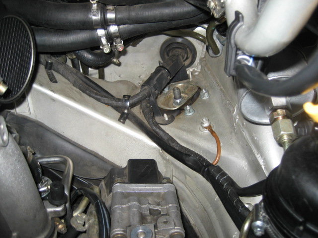
Somewhere back there is the left rear strut assembly mount.
The shocks arrived last night, so I got a start on installing the fronts this morning. Here is the play-by-play for one of the fronts. The other should be the same.
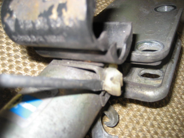
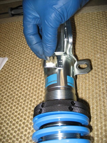
First, I removed the clips from the shocks. I only had 2 on each one, but should have had 3. The last one was long gone and replaced by zip ties. I'll add a new one to my next parts order.
The ground wire clip had a pin in the middle of it that I grabbed with some pliers and removed.
Once the pin was removed, I used a screwdriver to carefully pry the old clip out of the old strut.
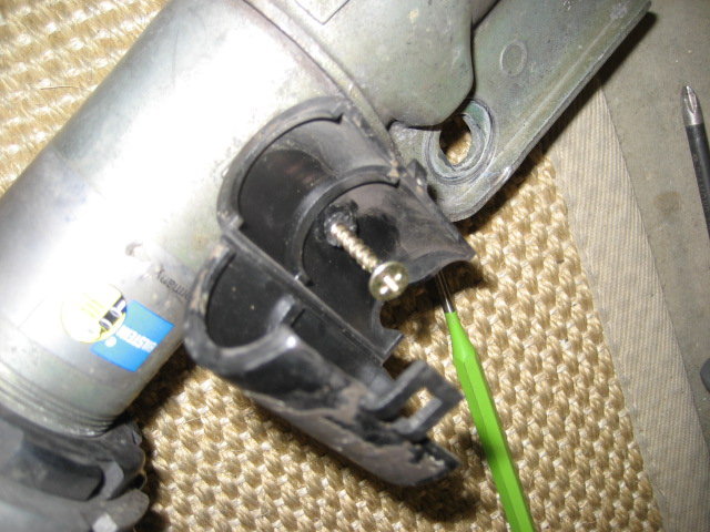
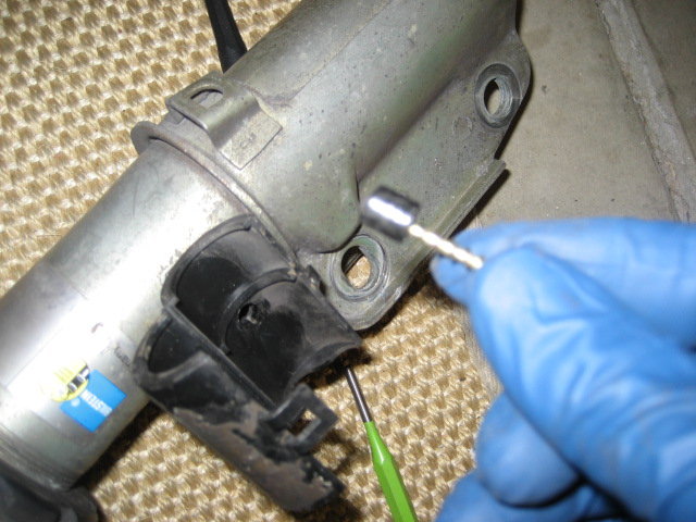
I was unable to use pliers to removed the pin from the next clip, so I used a spare screw as a handle by threading it into the pin.
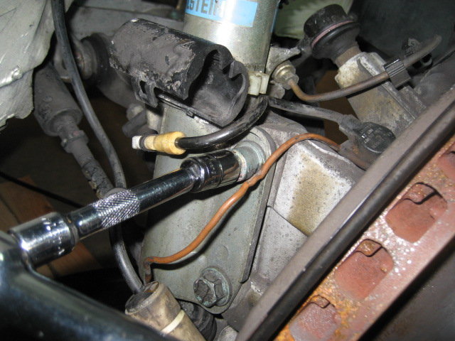
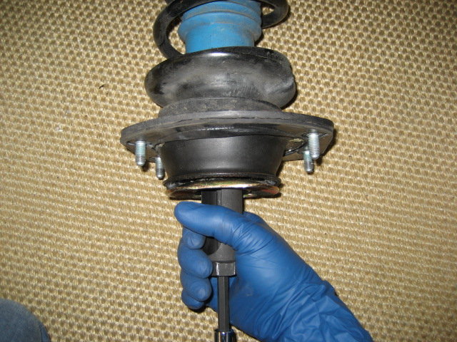
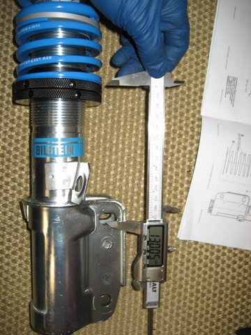
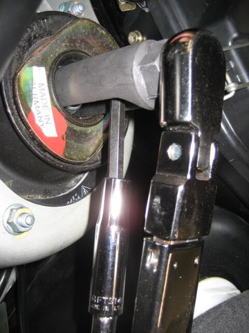
I removed the top nut on the old strut using the same O2 sensor socket mentioned early. Note that I did not need to compress the spring with my configuration of the old-style B6s and M033 springs.
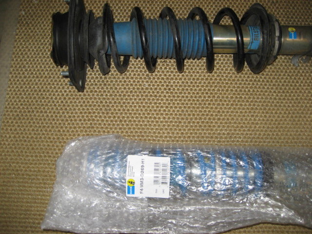
I grabbed the new shock and unwrapped it. I looks like there are right and left versions.
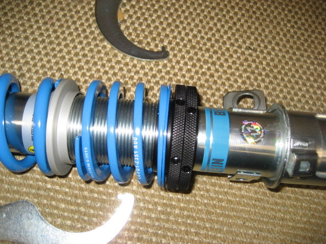
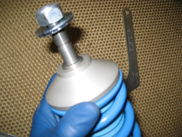
I noticed that the upper spring perch would not easily nest into its position on the strut shaft because the tension of the spring. I used the spanners included in the Bilstein kit to unlock, then spin down the adjusting nuts to their lowest position in order to relieve this spring tension and make it idiot proof to assemble the strut.
Once lowering the adjusting nuts, I verified that the upper perch now easily fits down into place.
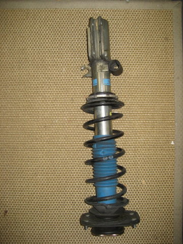
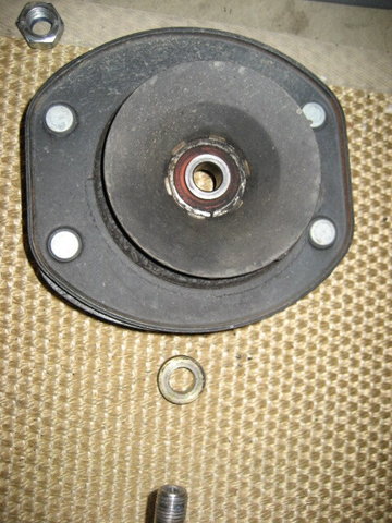
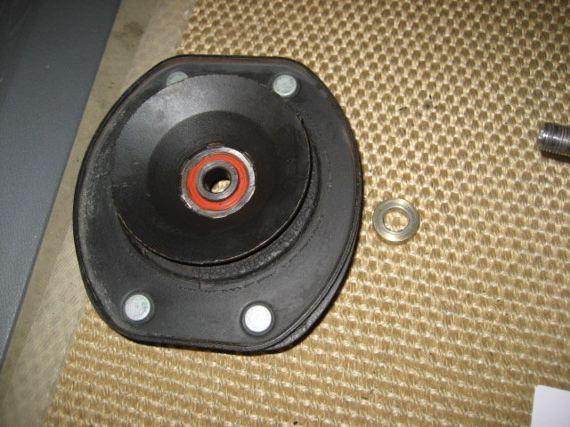
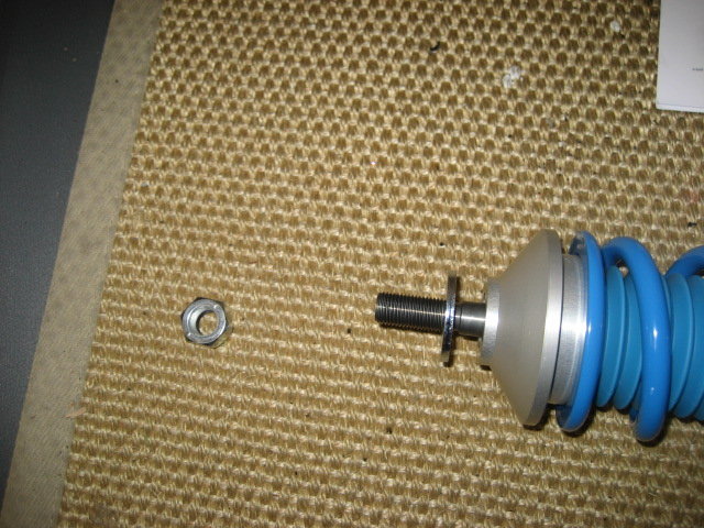
Following the included instructions, I removed, and cleaned the two parts from the old suspension that are used in the PSS10 assembly. They are the top hat and the brass-looking spacer.
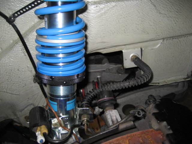
This is how the PSS10 front shock looked after unwrapping.
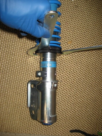
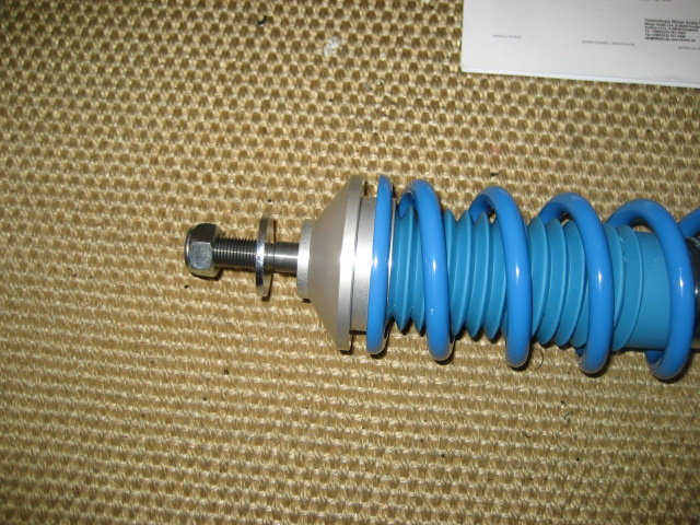
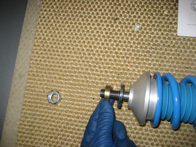
I removed the top nut, then slid on the spacer and top hat before reinstalling the top nut.
I then tightened down the top nut to be later torqued to spec once on the car.
Now that the top nut was secure, I raised the adjusting nuts to the middle of the specified adjustment range. I'll fine tune ride hight one finished with the overall installation.
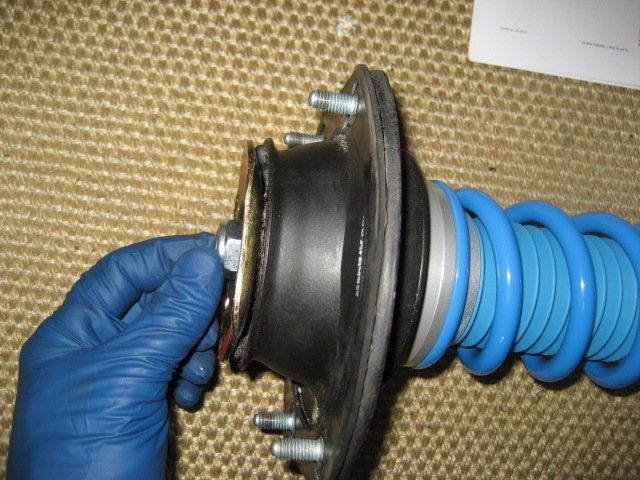
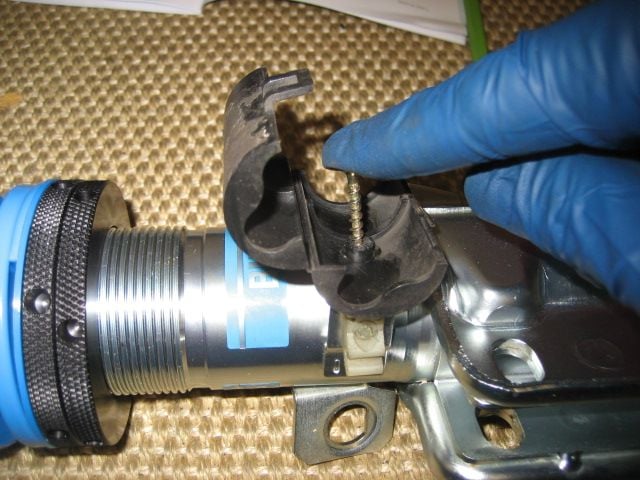
All that was needed to complete the assembly was adding the 2 clips.
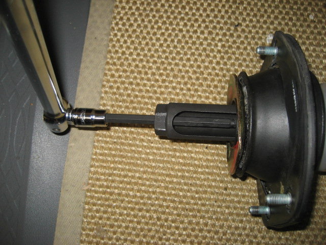
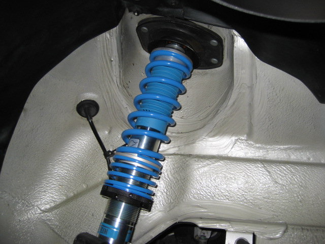
It was now time to install the completed assembly into the car. I started by holding it in place and carefully installing the top nuts by hand. I snugged this up, and adjusted to final torque later.
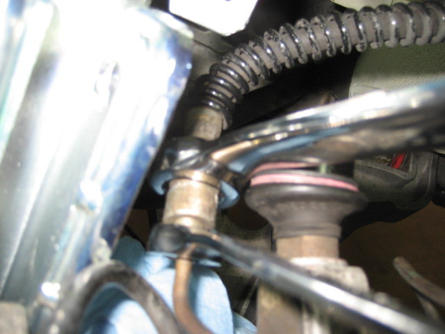
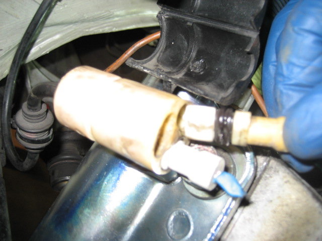
I decided to not cut the shiny new shocks and prepared to disconnect the brake line. I used a mop handle to apply a tiny bit of pressure on the brake pedal. This effectively closed off the supply side of the master cylinder and prevented fluid from running all over my garage floor.
Using line wrenches, I disconnected the brake line and fed the flexible end through the new strut assembly.
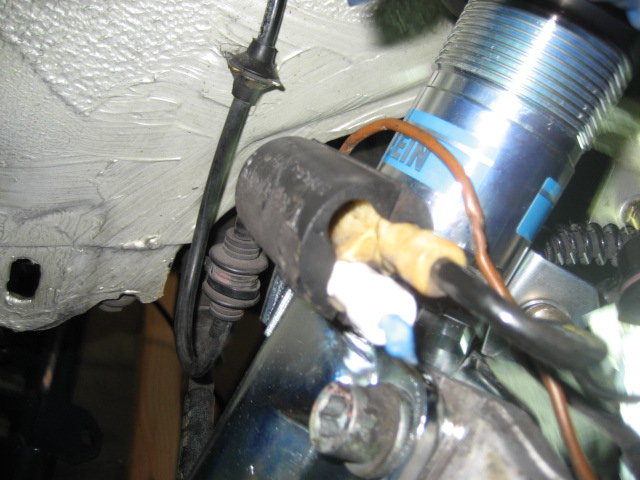
I temporarily inserted a screwdriver through the strut and wheel carrier to pry the wheel carrier into position. Once in position, I was able to reconnect the brake line and tighten it up.
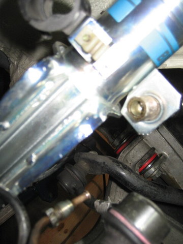
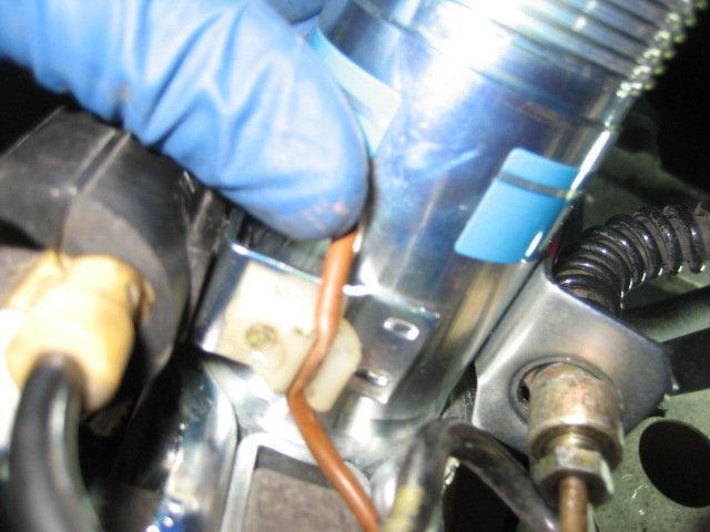
I moved my screwdriver to the lower hole to free the top hole to accept the hex screw.
I forgot to photograph every detail of this step, but I installed the lower bolt, pushed on the top of the wheel carrier for max negative camber then torqued down the two fasters. The alignment shop will adjust camber later.
In the home stretch, I reinstalled the electrical connectors and brake line clip.
One note. I believe that the shock top nut should be torqued to spec with the weight on the wheel, either the car down off the jacks or the wheel jacked up to normal location. Since the shock top mount is a rubber part, you would use this technique as you do on any rubber suspension bushing.
I could be wrong, so let me know if I'm misunderstanding something.


 12-14-2016, 10:38 AM